Installation
Preparing the Machine
-
Park the machine on a level surface.
-
Engage the parking brake.
-
Shut off the machine.
-
Remove the cutting unit from the machine; refer to your machine Operator’s Manual.
Mounting the Brush Brackets
Parts needed for this procedure:
| Left brush bracket | 1 |
| Right brush bracket | 1 |
| Hex-socket-head screw (5/16 x 1 inch) | 6 |
| Flange locknut (5/16) | 4 |
| Spacer nut | 2 |
| Rubber bumper | 2 |
| Jam nut | 2 |
| Level adjustment screw | 2 |
| Locknut (5/16 inch) | 2 |
| Locknut (1/4 inch) | 2 |
| Left brush rod | 1 |
| Right brush rod | 1 |
-
If the cutting unit is attached to the traction unit, position the traction unit on a level surface, engage the parking brake, shut off the traction unit, remove the key (if equipped), and disconnect the battery.
-
Remove the 2 hex-socket-head screws securing the basket mounting rods at each side of the cutting unit.
-
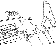
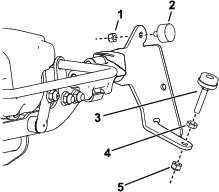
Install a brush bracket and basket mounting rod removed in step 2 to each side of the cutting unit using 2 hex-socket-head screws (5/16 x 1 inch) and 2 locknuts (5/16 inch) as shown in Figure 1.
-
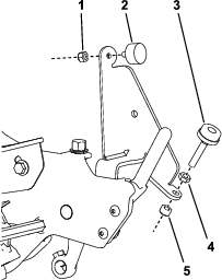
Install a rubber bumper to both brush brackets with a locknut (1/4 inch) as shown in Figure 2.
-
Install a level adjustment screw to both brush brackets as shown in Figure 2.
-
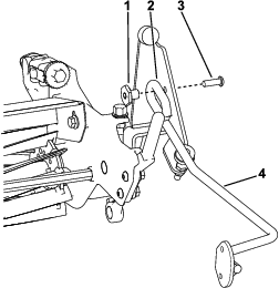
Install a brush rod to both brackets with a hex-socket-head screw (5/16 x 1 inch) and a spacer nut (Figure 3).
Ensure that the welded loop on the brush rod is positioned as shown in Figure 3.
Mounting the Brush Brackets
Parts needed for this procedure:
| Left brush bracket | 1 |
| Right brush bracket | 1 |
| Hex-socket-head screw (5/16 x 1 inch) | 2 |
| Flange locknut (5/16) | 4 |
| Spacer nut | 2 |
| Rubber bumper | 2 |
| Jam nut | 2 |
| Level adjustment screw | 2 |
| Locknut (1/4 inch) | 2 |
| Left brush rod | 1 |
| Right brush rod | 1 |
| Bolt (5/16 x 3/4 inch) | 4 |
-
If the cutting unit is attached to the traction unit, position the traction unit on a level surface, engage the parking brake, shut off the traction unit, remove the key (if equipped), and disconnect the battery.
-
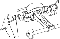
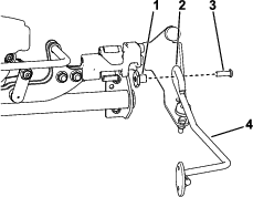
Install a brush bracket to each side of the cutting unit using 2 bolts (5/16 x 3/4 inch) as shown in Figure 4.
-
Install a rubber bumper to both brush brackets with a locknut (1/4 inch) as shown in Figure 5.
-
Install a level adjustment screw to both brush brackets as shown in Figure 5.
-
Install a brush rod to both brackets with a hex-socket-head screw (5/16 x 1 inch) and a spacer nut (Figure 6).
Ensure that the welded loop on the brush rod is positioned as shown in Figure 6.
Mounting the Brush
Parts needed for this procedure:
| Brush | 1 |
| Brush tab | 2 |
| Lag screw (5/16 x 1-1/2 inches) | 4 |
| Flange-head bolt (1/4 x 3/4 inches) | 4 |
| Flange locknut (1/4 inch) | 4 |
-
Ensure that the brush is the correct length for your cutting unit; cut the brush at the marked lines as necessary for your cutting unit width.
-
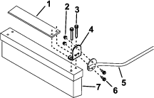
Mount a brush tab to each end of the brush with 2 lag screws (5/16 x 1-1/2 inches). Position the tabs as shown in Figure 7.
Note: The brush bristles are cut at an angle. Mount the brush so the longer bristles are closest to the traction unit when mowing.
-
Secure a brush rod to each brush tab with 2 flange-head bolts (1/4 x 3/4 inches) and flange locknuts (1/4 inch) as shown in Figure 7.
-
With the brush in the operating position on level ground, adjust both level-adjustment screws from 0.6 cm (1/4 inch) to 1.3 cm (1/2 inch) below the brush rods. Tighten the jam nuts. Adjust as needed to maintain desired ground contact.
Note: The ends of the brush bristles should be flat on the ground during the mowing operation. If the brush hops during operation, rotate the brush so that only the front bristles touch the surface and the rear bristles are less than 1.3 cm (1/2 inch) above the surface.
-
Rotate the brush upward and secure the rods when the brush is not required.