| Maintenance Service Interval | Maintenance Procedure |
|---|---|
| Before each use or daily |
|
Introduction
Read this information carefully to learn how to operate and maintain your product properly and to avoid injury and product damage. You are responsible for operating the product properly and safely.
You may contact Toro directly at www.Toro.com for product safety and operation training materials, accessory information, help finding a dealer, or to register your product.
Whenever you need service, genuine Toro parts, or additional information, contact an Authorized Service Dealer or Toro Customer Service and have the model and serial numbers of your product ready. Figure 1 identifies the location of the model and serial numbers on the product. Write the numbers in the space provided.
This manual identifies potential hazards and has safety messages identified by the safety alert symbol (Figure 2), which signals a hazard that may cause serious injury or death if you do not follow the recommended precautions.

This manual uses 2 words to highlight information. Important calls attention to special mechanical information and Note emphasizes general information worthy of special attention.
This machine is a utility vehicle intended to be used by professional, hired operators in commercial applications. It is primarily designed for the transport of implements used in such applications. This vehicle allows for the safe transport of an operator and one passenger in the identified seats. The bed of this vehicle is not suitable for any riders.
This product complies with all relevant European directives; for details, please see the separate product specific Declaration of Conformity (DOC) sheet.
Important: The engine in this product is not equipped with a spark arrested muffler. It is a violation of California Public Resource code Section 4442 to use or operate this engine on any forest-covered, brush covered, or grass-covered land as defined in CPRC 4126. Other states or federal areas may have similar laws.
Warning
CALIFORNIA
Proposition 65 Warning
The engine exhaust from this product contains chemicals known to the State of California to cause cancer, birth defects, or other reproductive harm.
Battery posts, terminals, and related accessories contain lead and lead compounds, chemicals known to the State of California to cause cancer and reproductive harm. Wash hands after handling.
Safety
Improper use or maintenance by the operator or owner can result in injury. To reduce the potential for injury, comply with these safety instructions and always pay attention to the safety alert symbol, which means Caution, Warning, or Danger—“personal safety instruction.” Failure to comply with the instruction may result in personal injury or death.
Safe Operating Practices
Important: The machine is designed primarily as an off-road vehicle and is not intended for extensive use on public roads.When using the machine on public roads, follow all traffic regulations and use any additional accessories that may be required by law, such as lights, turn signals, slow moving vehicle (SMV) sign, and others as required.
The Workman was designed and tested to offer safe service when operated and maintained properly. Although hazard control and accident prevention partially are dependent upon the design and configuration of the machine, these factors are also dependent upon the awareness, concern, and proper training of the personnel involved in the operation, maintenance and storage of the machine. Improper use or maintenance of the machine can result in injury or death.
This is a specialized utility vehicle designed for off–road use only. Its ride and handling will have a different feel than what drivers experience with passenger cars or trucks. So take time to become familiar with your machine.
Not all of the attachments that adapt to the machine are covered in this manual. See the specific Operator’s Manual provided with each attachment for additional safety instructions. Read these manuals.
To reduce the potential for injury or death, comply with the following safety instructions:
Before Operating
-
Operate the machine only after reading and understanding the contents of this manual.
-
Never allow children to operate the machine. Never allow adults to operate it without proper instructions. Only trained and authorized persons should operate this machine. Make sure all operators are physically and mentally capable of operating the machine.
-
This machine is designed to carry only you, the operator, and one passenger in the seat provided by the manufacturer. Never carry any other passengers on the machine.
-
Never operate the machine when under the influence of drugs or alcohol.
-
Become familiar with the controls and know how to stop the engine quickly.
-
Keep all shields, safety devices and decals in place. If a shield, safety device or decal is malfunctioning, illegible, or damaged, repair or replace it before operating the machine.
-
Always wear substantial shoes. Do not operate the machine while wearing sandals, tennis shoes, or sneakers. Do not wear loose fitting clothing or jewelry which could get caught in moving parts and cause personal injury.
-
Wearing safety glasses, safety shoes, long pants, and a helmet is advisable and required by some local safety and insurance regulations.
-
Keep everyone, especially children and pets, away from the areas of operation.
-
Before operating the machine, always check all parts of the machine and any attachments. If something is wrong, stop using machine. Make sure the problem is corrected before machine or attachment is operated again.
-
Since diesel fuel is highly flammable, handle it carefully.
-
Use an approved fuel container.
-
Do not remove the cap from the fuel tank when the engine is hot or running.
-
Do not smoke while handling fuel.
-
Fill the fuel tank outdoors and to about one inch below the top of tank (bottom of filler neck). Do not overfill.
-
Wipe up any spilled fuel.
-
-
Operate the machine only outdoors or in a well-ventilated area.
-
Use only an approved nonmetal, portable fuel container. Static electric discharge can ignite fuel vapors in a ungrounded fuel container. Remove the fuel container from the bed of the machine and place it on the ground away from the machine before filling. Keep the nozzle in contact with the container while filling. Remove equipment from machine bed before filling.
-
Check the safety-interlock system daily for proper operation. If a switch should malfunction, replace the switch before operating machine. After every two years, replace the interlock switches in the safety system, whether they are working properly or not.
Operation
-
The operator and passenger must use seat belts and remain seated whenever the machine is in motion. The operator should keep both hands on the steering wheel, whenever possible, and the passenger should use the hand holds provided. Keep arms and legs within the vehicle body at all times. Never carry passengers in the box or on attachments. Remember your passenger may not be expecting you to brake or turn and may not be ready.
-
Never overload your machine. The name plate (located under the middle of the dash) shows the load limits for the machine. Never overfill attachments or exceed the machine maximum gross vehicle weight (GVW).
-
When starting the engine:
-
Sit on the operator’s seat and ensure that the parking brake is engaged.
-
Disengage PTO (if so equipped) and return the hand throttle lever to the Off position (if so equipped).
-
Make sure the hydraulic-lift lever is in the center position.
-
Move shift lever to Neutral and press the clutch pedal.
-
Keep your foot off of the accelerator pedal.
-
Turn ignition switch to the On position. When the glow plug indicator goes off, the engine is ready to start.
-
Turn the ignition key to the Start position.
Note: The glow-plug indicator will turn on, for an additional 15 seconds, when the switch returns to the Start position.
-
-
Using the machine demands attention. Failure to operate machine safely may result in an accident, tip over of the machine, and serious injury or death. Drive carefully. To prevent tipping or loss of control, take the following precautions:
-
Use extreme caution, reduce speed, and maintain a safe distance around sand traps, ditches, creeks, ramps, any unfamiliar areas, or other hazards.
-
Watch for holes or other hidden hazards.
-
Use caution when operating the machine on a steep slope. Normally, travel straight up and down slopes. Reduce speed when making sharp turns or when turning on hillsides. Avoid turning on hillsides whenever possible.
-
Use extra caution when operating the vehicle on wet surfaces, at higher speeds, or with a full load. Stopping time will increase with a full load. Shift into a lower gear before starting up or down a hill.
-
When loading the bed, distribute the load evenly. Use extra caution if the load exceeds the dimensions of the machine/bed. Operate the vehicle with extra caution when handling off-center loads that cannot be centered. Keep loads balanced and secure to prevent them from shifting.
-
Avoid sudden stops and starts. Do not go from reverse to forward or forward to reverse without first coming to a complete stop.
-
Do not attempt sharp turns or abrupt maneuvers or other unsafe driving actions that may cause a loss of machine control.
-
Do not pass another machine traveling in the same direction at intersections, blind spots, or at other dangerous locations.
-
When dumping, do not let anyone stand behind the machine, and do not dump the load on any one’s feet. Release the tailgate latches from the side of box, not from behind.
-
Keep all bystanders away. Before backing up, look to the rear and ensure that no one is behind the machine. Back up slowly.
-
Watch out for traffic when near or crossing roads. Always yield the right of way to pedestrians and other machines. This machine is not designed for use on streets or highways. Always signal your turns or stop early enough so other persons know what you plan to do. Obey all traffic rules and regulations.
-
Never operate the machine in or near an area where there is dust or fumes in the air which are explosive. The electrical and exhaust systems of the machine can produce sparks capable of igniting explosive materials.
-
Always watch out for and avoid low overhangs such as tree limbs, door jambs, over head walkways, etc. Make sure there is enough room over head to easily clear the machine and your head.
-
If ever unsure about safe operation, stop work, and ask your supervisor.
-
-
Do not touch the engine, transaxle, radiator, muffler, or muffler manifold while engine is running or soon after it has stopped because these areas may be hot enough to cause burns.
-
If the machine ever vibrates abnormally, stop immediately, turn engine off, wait for all motion to stop and inspect for damage. Repair all damage before resuming operation.
-
Before getting off of the seat:
-
Stop the movement of the machine.
-
Set the parking brake.
-
Turn the ignition key to the Off position.
-
Remove the ignition key.
Note: If the machine is on an incline, block the wheels after getting off of the machine.
-
-
Lightning can cause severe injury or death. If lightning is seen or thunder is heard in the area, do not operate the machine; seek shelter.
Braking
-
Slow down before you approach an obstacle. This gives you extra time to stop or turn away. Hitting an obstacle can injure you and your passenger. In addition, it can damage the machine and its contents.
-
Gross Vehicle Weight (GVW) has a major impact on your ability to stop and/or turn. Heavy loads and attachments make the machine harder to stop or turn. The heavier the load, the longer it takes to stop.
-
Decrease the speed of the machine if the cargo box has been removed and there is no attachment installed on the machine. The braking characteristics change and fast stops may cause the rear wheels to lock up, which will affect the control of the machine.
-
Turf and pavement are much more slippery when they are wet. It can take 2 to 4 times longer to stop the machine on wet surfaces as on dry surfaces. If you drive through deep-standing water and get the brakes wet, they will not work well until they are dry. After driving through water, you should test the brakes to make sure they work properly. If they do not, drive slowly on a level ground while putting light pressure on the brake pedal. This will dry the brakes out.
Operating on Hills
Warning
Operating the machine on a hill may cause tipping or rolling of the machine, or the engine may stall and you could lose headway on the hill. This could result in personal injury.
-
Do not operate machine on excessively steep slopes.
-
Do not accelerate quickly or slam on the brakes when backing down a hill, especially with a load.
-
If the engine stalls or you lose headway on a hill, slowly back straight down the hill. Never attempt to turn the machine around.
-
Operate the machine slowly on a hill and use caution.
-
Avoid turning on a hill.
-
Reduce your load and the speed of the machine.
-
Avoid stopping on hills, especially with a load.
These extra cautions need to be taken when operating the machine on a hill:
-
Slow the machine down before starting up or down a hill.
-
If the engine stalls or you begin to lose momentum while climbing a hill, gradually apply the brakes and slowly back the machine straight down the hill.
-
Turning while traveling up or down hills can be dangerous. If you have to turn while on a hill, do it slowly and cautiously. Never make sharp or fast turns.
-
Heavy loads affect stability. Reduce the weight of the load and your ground speed when operating on hills or if the load has a high center of gravity. Secure the load to the cargo box of the machine to prevent the load from shifting. Take extra care when hauling loads that shift easily (liquid, rock, sand, etc.).
-
Avoid stopping on hills, especially with a load. Stopping while going down a hill will take longer than stopping on level ground. If the machine must be stopped, avoid sudden speed changes, which may initiate tipping or rolling of the machine. Do not slam on the brakes when rolling backward, as this may cause the machine to overturn.
-
If you will be using the machine on hilly terrain, you can install the optional ROPS Kit.
Operating on Rough Terrain
Reduce the ground speed of the machine and load carried in the machine when operating on rough terrain, uneven ground, and near curbs, holes, and other sudden changes in terrain. Loads may shift, causing the machine to become unstable.
If you will be using the machine on rough terrain, you can install the optional ROPS Kit.
Warning
Sudden changes in terrain may cause abrupt steering wheel movement, possibly resulting in hand and arm injuries.
-
Reduce your speed when operating on rough terrain and near curbs.
-
Grip the steering wheel loosely around the perimeter keeping thumbs up and out of the way of the steering wheel spokes.
Loading and Dumping
The weight and position of cargo and passenger can affect the stability and handling of the machine. Be aware of the following condition to avoid losing control of the machine or tipping it over:
-
Do not exceed the rated weight capacity of the machine when operating it with a load in the cargo box, when towing a trailer, or both; refer to Specifications.
-
Use caution when operating the machine on a hillside or on rough terrain, particularly with a load in the cargo box or when towing a trailer or both.
-
Use caution when carrying tall loads in the cargo box.
-
Be aware that the stability and control of the machine are reduced when the load in the cargo box is poorly distributed.
-
Carrying oversized loads in the cargo box changes the stability of the machine.
-
The steering, braking , and stability of the machine are affected when carrying a load where the weight of the material cannot be bound to the machine such as the liquid in a large tank.
Warning
The weight of the box may be heavy. Hands or other body parts could be crushed.
-
Keep hands and other body parts clear when lowering the box.
-
Do not dump materials on bystanders.
-
-
Never dump a loaded cargo box while the machine is sideways on a hill. The change in weight distribution may cause the machine to overturn.
-
When operating with a heavy load in the cargo box, reduce your speed and allow for sufficient braking distance. Do not suddenly apply the brakes. Use extra caution on slopes.
-
Be aware that heavy loads increase your stopping distance and reduce your ability to turn quickly without tipping over.
-
The rear cargo space is intended for load carrying purposes only, not for passengers.
-
Never overload your machine. The name plate (located under the middle of the dash) shows the load limits for the machine. Never overfill attachments or exceed the machine maximum gross vehicle weight (GVW).
Maintenance
Warning
Hydraulic fluid escaping under pressure can have sufficient force to penetrate skin and do serious damage. If fluid is injected into the skin it must be surgically removed within a few hours by a doctor familiar with this form of injury or gangrene may result.
Keep your body and hands away from pinhole leaks or nozzles that eject hydraulic fluid under high pressure. Use paper or cardboard, not hands, to search for leaks.
-
Before servicing or making adjustments to the machine, stop the engine, set the parking brake, and remove the key from the ignition to prevent accidental starting of the engine.
-
Never work under a raised bed without placing the bed safety support on the fully extended cylinder rod.
-
Make sure that all hydraulic-line connectors are tight, and that all hydraulic hoses and lines are in good condition before applying pressure to the system.
-
Before disconnecting or performing any work on the hydraulic system, all pressure in the system must be relieved by stopping the engine, cycling the dump valve from raise to lower and/or lowering box and attachments. Place the remote hydraulics lever in the float position. If the box must be in raised position, secure it with the safety support.
-
To make sure that the entire machine is in good condition, keep all nuts, bolts, and screws properly tightened.
-
To reduce the potential fire hazard, keep the engine area free of excessive grease, grass, leaves, and accumulation of dirt.
-
If the engine must be running to perform a maintenance adjustment, keep hands, feet, clothing, and any parts of the body away from the engine and any moving parts. Keep everyone away.
-
Do not overspeed the engine by changing the governor settings. The maximum engine speed is 3650 RPM. To ensure safety and accuracy, have an Authorized Toro Distributor check the maximum engine speed with a tachometer.
-
If major repairs are ever needed or assistance is required, contact an Authorized Toro Distributor.
-
To be sure of optimum performance and safety, always purchase genuine Toro replacement parts and accessories. Replacement parts and accessories made by other manufacturers could be dangerous. Altering this vehicle in any manner may affect the vehicle’s operation, performance, durability or its use may result in injury or death. Such use could void the product warranty of The Toro® Company.
Sound Pressure
This unit has a sound pressure level at the operator’s ear of 75 dBA, which includes an Uncertainty Value (K) of 1 dBA.
The sound pressure level was determined according to the procedures outlined in EN ISO 11201.
Vibration
Hand-Arm
-
Measured vibration level for right hand = 0.34 m/s2
-
Measured vibration level for left hand = 0.43 m/s2
-
Uncertainty Value (K) = 0.5 m/s2
Measured values were determined according to the procedures outlined in EN 1032.
Whole Body
-
Measured vibration level = 0.33 m/s2
-
Uncertainty Value (K) = 0.5 m/s2
Measured values were determined according to the procedures outlined in EN 1032.
Safety and Instructional Decals
|
Safety decals and instructions are easily visible to the operator and are located near any area of potential danger. Replace any decal that is damaged or lost. |


Setup
Note: Determine the left and right sides of the machine from the normal operating position.
Installing the Steering Wheel (TC models only)
Parts needed for this procedure:
| Steering wheel | 1 |
-
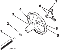
Release the tabs on the back of the steering wheel that hold the center cover in place, and remove the cover from the hub of the steering wheel.
-
Remove the locknut and washer from the steering shaft.
-
Slide the steering wheel and washer onto the shaft. Align the steering wheel on the shaft so that the cross beam is horizontal when the tires are pointed straight ahead and the thicker spoke of the steering wheel is downward.
Note: The dust cover is position onto the steering shaft at the factory.
-
Secure the steering wheel to the shaft with the locknut (Figure 3). Torque the locknut to 24 to 29 N-m (18 to 22 ft-lb)
-
Align the tabs of the cover with the slots in the steering wheel, and snap the cover onto the steering-wheel hub (Figure 3).
Installing the Rollover Protection System (ROPS)
Parts needed for this procedure:
| ROPS frame | 1 |
| Bolt (1/2 inch) | 6 |
-
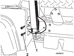
Align each side of the ROPS with the mounting holes in the frame at each side of the vehicle as shown in Figure 4.
-
Secure each side of the ROPS to frame with 3 flanged bolts (1/2 x 1-1/4 inch), and tighten the bolts to 115 N-m (85 ft-lb).
Checking the Fluid Levels
-
Check the engine-oil level before and after the engine is first started; refer to Checking the Engine-oil Level.
-
Check the transaxle/hydraulic-fluid level before the engine is first started; refer to Checking the Transaxle/Hydraulic-fluid Level.
-
Check the brake-fluid level before the engine is first started; refer to Checking the Brake-fluid Level.
-
Check the coolant level; refer to Checking the Coolant Level.
Product Overview
Note: Determine the left and right sides of the machine from the normal operating position.
Accelerator Pedal
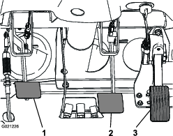
The accelerator pedal (Figure 5) gives the operator the ability to vary the engine and ground speed of the machine when the transmission is in gear. Pressing the pedal increases the engine rpm and ground speed. Releasing the pedal decreases the engine rpm and ground speed of the machine.
Clutch Pedal
The clutch pedal (Figure 5) must be fully pressed to disengage clutch when starting the engine or shifting transmission gears. Release the pedal smoothly when the transmission is in gear to prevent unnecessary wear on the transmission and other related parts.
Important: Do not ride the clutch pedal during operation. The clutch pedal must be fully out or the clutch will slip causing heat and wear. Never hold the machine stopped on a hill using the clutch pedal. Damage to the clutch may occur.
Brake Pedal
The brake pedal (Figure 5) is used to apply service brakes to stop or slow the machine.
Caution
Worn or maladjusted brakes may result in personal injury. If the brake pedal travels to within 3.8 cm (1-1/2 inches) of the machine floor board, the brakes must be adjusted or repaired.
Gear-shift Lever
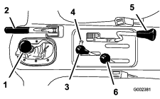
Fully press the clutch pedal and move the shift lever (Figure 6) into the desired gear selection. A diagram of the shift pattern is shown below.

Important: Do not shift the transaxle to the reverse or forward gear unless the vehicle is standing still. Damage to the transaxle may occur.
Caution
Down shifting from too high a speed can cause the rear wheels to skid resulting in loss of machine control as well as clutch and/or transmission damage. Shift smoothly to avoid grinding gears.
Differential Lock
The differential lock allows rear axle to be locked for increased traction. The differential lock (Figure 7) may be engaged when the machine is in motion. Move the lever forward and to the right to engage the lock.
Note: Machine motion plus a slight turn is required to engage or disengage differential lock.
Caution
Turning with the differential lock on can result in loss of machine control. Do not operate with differential lock on when making sharp turns or at high speeds; refer to Adjusting Differential-lock Cable.
Parking Brake
Whenever the engine is shut off, set the parking brake (Figure 7) in order to prevent the machine from accidentally moving.
-
To set the parking brake, pull back on the lever.
-
To release, push the lever forward.
Note: Release the parking brake before moving the machine.
If you park the machine on a steep grade, set the parking brake, shift the transmission into first gear on a uphill grade or reverse gear on a down hill grade, and place chocks at the down hill side of the wheels.
Hydraulic Lift
The hydraulic lift raises and lowers the bed. Move it rearward to raise the bed, and forward to lower it (Figure 7).
Important: When lowering the bed, hold the lever in the forward position for 1 or 2 seconds after the bed contacts the frame to secure it in the lowered position. Do not hold the hydraulic lift in either the raise or lower position, for more than 5 seconds, once the cylinders have reached the end of their travel.
Hydraulic-lift Lock
The hydraulic-lift lock locks the lift lever, so the hydraulic cylinders do not operate when the machine is not equipped with a bed (Figure 7). It also locks the lift lever in the On position when using the hydraulics for attachments.
High–Low Range Shifter
The high–low range shifter adds 3 additional speeds for precise speed control (Figure 7).
-
The machine must be completely stopped before shifting between the High and Low range.
-
Shift only on level ground.
-
Press the clutch pedal fully.
-
Move the lever fully forward for High and fully rearward for Low.
High is for higher speed driving on level, dry surfaces with light loads.
Low is for low-speed driving. Use this range when greater than normal power or control is required. For example, steep grades, difficult terrain, heavy loads, slow speed but high-engine speed (spraying).
Important: There is a location between High and Low in which the transaxle is in neither range. Do not use this position as a neutral position because the vehicle could move unexpectedly if the High–Low shifter is bumped and the gear-shift lever is in gear.
Ignition Switch
Use the ignition switch (Figure 8) to start and stop the engine. It has 3 positions: Off, On, and Start. Rotate the key clockwise to the Start position to engage the starter motor. Release the key when the engine starts. The key will move automatically to the On position. To shut the engine off, rotate the key counterclockwise to the Off position.
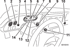
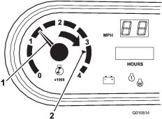
Hour Meter
The hour meter indicates the total hours of machine operation. The hour meter (Figure 8) starts to function whenever the key switch is rotated to the On position or if the engine is running.
Speed-limiter Switch
Move the speed-limiter switch (Figure 8) to the slow position and remove the key. The switch limits the engine to 2,200 rpm when the machine is in third gear in the High range, which limits the top speed to 21 km/h (13 mph).
Light Switch
Push the light switch (Figure 8) to toggle the headlights on or off.
Oil-pressure-warning Light
The oil-pressure-warning light glows (Figure 8) if the engine-oil pressure drops below a safe level while the engine is running. If the light flickers or remains on, stop the vehicle, turn off the engine, and check the oil level. If the oil level is low, but adding oil does not cause the light to go out when the engine is restarted, turn the engine off immediately and contact your local Toro distributor for assistance.
Check the operation of warning lights as follows:
-
Apply the parking brake.
-
Turn the ignition key to the On/Preheat position, but do not start the engine.
Note: The oil pressure light should glow red. If the light does not function, either a bulb is burned out or there is a malfunction in the system which must be repaired.
Note: If engine was just turned off, it may take 1 to 2 minutes for the light to come on.
Coolant-temperature Gauge and Light
Registers the coolant temperature in the engine. Operates only when the ignition switch is in On position (Figure 8). The indicator light illuminates blinking red if the engine overheats.
Charge Indicator
Illuminates when battery is being discharged. If the light illuminates during operation, stop the machine, turn off the engine, and check for possible causes, such as the alternator belt (Figure 8).
Important: If the alternator belt is loose or broken, do not operate the machine until adjustment or repair is complete. Failure to observe this precaution may result in damage to the engine.
Check the operation of warning lights as follows:
-
Apply the parking brake.
-
Turn the ignition key to the On/Preheat position, but do not start the engine. The coolant temperature, charge indicator, and oil-pressure lights should glow. If any light does not function, either a bulb is burned out or there is a malfunction in the system which must be repaired.
Fuel Gauge
The fuel gauge shows the amount of fuel in the tank. It operates only when ignition switch is in the On position (Figure 8). Red indicates low fuel level and blinking red indicates near empty.
High-flow Hydraulics Switch (TC models only)
Turn on the switch to activate the high-flow hydraulics (Figure 8).
Horn Button (TC models only)
Pressing the horn button activates the horn (Figure 8).
Tachometer
Check-engine Light
The light will illuminate to notify operator of a engine malfunction; refer to Responding to a Check-engine Light.
Speedometer
Registers the ground speed of the machine (Figure 8). The speedometer is in mph but can easily converted to km/h; refer to Converting the Speedometer.
Power Point
Use the power point (Figure 8) to power optional 12 volt electrical accessories.
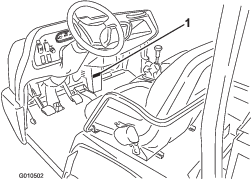
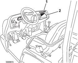
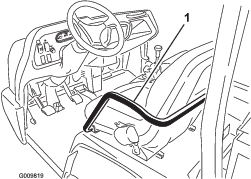
Passenger Hand Hold
The passenger hand hold is located on the dashboard (Figure 10).
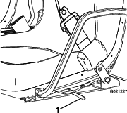
Seat-adjusting Lever
The seats can be adjusted fore and aft for operator comfort (Figure 11).
Note: Specifications and design are subject to change without notice.
| Overall Width | 160 cm (63 inches) |
| Overall Length | Without bed: 326 cm (128 inches)With full bed: 331 cm (130 inches)With 2/3 bed in rear-mounting location: 346 cm (136 inches) |
| Base Weight (Dry) | Model 07383—736 kg (1623 lb)Model 07384—885 kg (1951 lb)Model 07384H—885 kg (1951 lb)Model 07384TC—921.6 kg (2032 lb)Model 07386—912 kg (2010 lb)Model 07386H—912 kg (2010 lb)Model 07386TC—948 kg (2091 lb) |
| Rated Capacity(includes 91 kg (200 lb) operator, 91 kg (200 lb) passenger and loaded attachment) | Model 07383—1623 kg (3577 lb)Model 07384—1474 kg (3249 lb)Model 07384H—1474 kg (3249 lb)Model 07384TC—1437 kg (3168 lb)Model 07386—1447 kg (3190 lb)Model 07386H—1447 kg (3190 lb)Model 07386TC—1410 kg (3109 lb) |
| Maximum Gross Vehicle Weight | 2359 kg (5200 lb) |
| Tow Capacity | Tongue weight: 272 kg (600 lb)Maximum trailer weight: 1587 kg (3,500 lb) |
| Ground Clearance | 18 cm (7 inches) with no load |
| Wheel Base | 118 cm (70 inches) |
| Wheel Tread (center line to center line) | Front: 117 cm (46 inches)Rear: 121 cm (48 inches) |
| Height | 191 cm (75 inches) to top of ROPS |
Attachments/Accessories
A selection of Toro approved attachments and accessories is available for use with the machine to enhance and expand its capabilities. Contact your Authorized Service Dealer or Distributor or go to www.Toro.com for a list of all approved attachments and accessories.
Operation
Note: Determine the left and right sides of the machine from the normal operating position.
Caution
Before servicing or making adjustments to the machine, stop the engine, set the parking brake, and remove the key from the switch. Remove any load material from the bed or other attachment before working under a raised bed. Never work under a raised bed without positioning the safety support on a fully extended cylinder rod.
Operating the Cargo Box
Note: Center loads in the cargo box if possible.
Note: Remove all cargo from the box before lifting the box up to service the machine.
Raising the Cargo Box
Warning
Driving the machine with the cargo box raised may cause the machine to tip or roll easier. The box structure may become damaged if you operate the machine with the box raised.
-
Only operate the machine when the cargo box is down.
-
After emptying the cargo box, lower it.
Caution
If a load is concentrated near the back of the cargo box when you release the latches, the box may unexpectedly tip open injuring you or bystanders.
-
Center loads in the cargo box if possible.
-
Hold the cargo box down and ensure that no one is leaning over the box or standing behind it when releasing the latches.
-
Remove all cargo from the box before lifting the box up to service the machine.
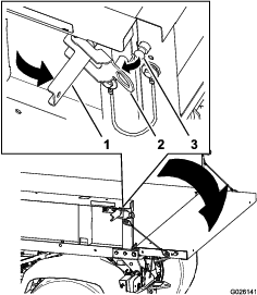
Move the lever backward to raise the cargo box (Figure 12).
Lowering the Box
Warning
The weight of the box may be heavy. Hands or other body parts could be crushed.
Keep hands and other body parts clear when lowering the box.
Move the lever forward to lower the cargo box (Figure 12).
Opening the Tailgate
-
Ensure that the cargo box is lowered completely.
-
Open the latches on the left and right side of the cargo box and lower the tailgate (Figure 13).
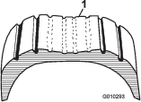
Checking the Engine-oil Level
Engine oil type: Detergent engine oil API SJ or higher
Engine-oil viscosity: 10W-30; Choose an engine-oil viscosity according to the ambient-air temperature to the table in Figure 14.

The engine is shipped with oil in the crankcase; however, you should check the oil level before and after the engine is first started.
Note: The best time to check the engine oil is when the engine is cool before it has been started for the day. If it has already been run, allow the oil to drain back down to the sump for at least 10 minutes before checking. If the oil level is at or below the Add mark on the dipstick, add oil to bring the oil level to the Full mark. Do not overfill the engine with oil. If the oil level is between the Full and Add marks, no additional oil is required.
-
Position the machine on a level surface.
-
Remove the dipstick (Figure 15) and wipe it with a clean rag.
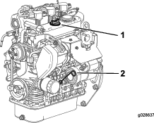
-
Insert the dipstick into the tube and make sure it is seated fully (Figure 15).
-
Remove dipstick and check the level of the oil (Figure 15).
-
If the oil level is low, remove the filler cap (Figure 15), and add enough oil to raise the level to the Full mark on the dipstick.
Note: When adding oil, remove dipstick to allow proper venting. Pour the oil slowly and check the level often during this process. Do not overfill the engine with oil.
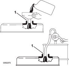
Important: When adding engine oil or filling oil, there must be clearance between the oil fill device and the oil fill hole in the valve cover as shown in Figure 16. This clearance is necessary to permit venting when filling, which prevents oil from overrunning into the breather.
-
Install the dipstick firmly in place (Figure 15).
Responding to a Check-engine Light
Note: Engine fault code information can only be accessed by your Toro commercial products service staff.
-
Park the vehicle in a safe manner as soon possible.
-
Contact your authorized Toro service dealer.
Note: Schedule a service call or bring the machine in to be analyzed.
Adding Fuel
-
For best results, use only clean, fresh (less than 30 days old), unleaded gasoline with an octane rating of 87 or higher ((R+M)/2 rating method).
-
Ethanol: Gasoline with up to 10% ethanol (gasohol) or 15% MTBE (methyl tertiary butyl ether) by volume is acceptable. Ethanol and MTBE are not the same. Gasoline with 15% ethanol (E15) by volume is not approved for use. Never use gasoline that contains more than 10% ethanol by volume, such as E15 (contains 15% ethanol), E20 (contains 20% ethanol), or E85 (contains up to 85% ethanol ). Using unapproved gasoline may cause performance problems and/or engine damage which may not be covered under warranty.
-
Do not use gasoline containing methanol.
-
Do not store fuel either in the fuel tank or fuel containers over the winter unless a fuel stabilizer is used.
-
Do not add oil to gasoline.
Danger
In certain conditions, gasoline is extremely flammable and highly explosive. A fire or explosion from gasoline can burn you and others and can damage property.
-
Fill the fuel tank outdoors, in an open area, when the engine is cold. Wipe up any gasoline that spills.
-
Never fill the fuel tank inside an enclosed trailer.
-
Do not fill the fuel tank completely full. Add gasoline to the fuel tank until the level is 6 to 13 mm (1/4 to 1/2 inch) below the bottom of the filler neck. This empty space in the tank allows gasoline to expand.
-
Never smoke when handling gasoline, and stay away from an open flame or where gasoline fumes may be ignited by a spark.
-
Store gasoline in an approved container and keep it out of the reach of children. Never buy more than a 30-day supply of gasoline.
-
Do not operate without entire exhaust system in place and in proper working condition.
Danger
In certain conditions during fueling, static electricity can be released causing a spark which can ignite the gasoline vapors. A fire or explosion from gasoline can burn you and others and can damage property.
-
Always place gasoline containers on the ground away from your vehicle before filling.
-
Do not fill gasoline containers inside a vehicle or on a truck or trailer bed because interior carpets or plastic truck bed liners may insulate the container and slow the loss of any static charge.
-
When practical, remove gas-powered equipment from the truck or trailer and refuel the equipment with its wheels on the ground.
-
If this is not possible, then refuel such equipment on a truck or trailer from a portable container, rather than from a gasoline dispenser nozzle.
-
If a gasoline dispenser nozzle must be used, keep the nozzle in contact with the rim of the fuel tank or container opening at all times until fueling is complete.
Warning
Gasoline is harmful or fatal if swallowed. Long-term exposure to vapors can cause serious injury and illness.
-
Avoid prolonged breathing of vapors.
-
Keep face away from nozzle and gas tank or conditioner bottle opening.
-
Avoid contact with skin; wash off spillage with soap and water.
Using Stabilizer/Conditioner
Use a fuel stabilizer/conditioner in the machine to provide the following benefits:
-
Keeps gasoline fresh during storage of 90 days or less. For longer storage it is recommended that the fuel tank be drained.
-
Cleans the engine while it runs
-
Eliminates gum-like varnish buildup in the fuel system, which causes hard starting
Important: Do not use fuel additives containing methanol or ethanol.
Add the correct amount of gas stabilizer/conditioner to the gas.
Note: A fuel stabilizer/conditioner is most effective when mixed with fresh gasoline. To minimize the chance of varnish deposits in the fuel system, use fuel stabilizer at all times.
Filling the Fuel Tank
-
Clean the area around the fuel-tank cap.
-
Remove the fuel-tank cap (Figure 17).
-
Fill the tank to about one inch below the top of the tank, (bottom of the filler neck), then install the cap.
Note: Do not overfill the fuel tank.
-
Wipe up any fuel that may have spilled to prevent a fire hazard.
Checking the Coolant Level
| Maintenance Service Interval | Maintenance Procedure |
|---|---|
| Before each use or daily |
|
Cooling system capacity: 3.7 L (4 US qt)
Coolant type: a 50/50 solution of water and permanent ethylene-glycol antifreeze.
Caution
If the engine has been running, the pressurized, hot coolant can escape and cause burns.
-
Do not open the radiator cap.
-
Allow the engine to cool at least 15 minutes or until the reserve tank is cool enough to touch without burning your hand.
-
Use a rag when opening the reserve tank cap, and open the cap slowly to allow steam to escape.
-
Do not check the coolant level at the radiator; only check the coolant level at the reserve tank.
-
Park the machine on a level surface.
-
Check the coolant level inside the reserve tank (Figure 18).
Note: The coolant should be up to the bottom of the filler neck when the engine is cold.
-
If coolant is low, remove the reserve tank cap and add a 50/50 mixture of water and permanent ethylene-glycol antifreeze.
Note: Do not overfill the reserve tank with coolant.
-
Install the reserve-tank cap.
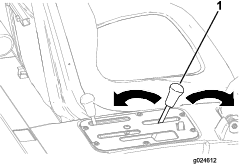
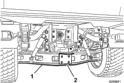
Checking the Transaxle/Hydraulic-fluid Level
| Maintenance Service Interval | Maintenance Procedure |
|---|---|
| Before each use or daily |
|
Transaxle fluid type: Dexron III ATF
-
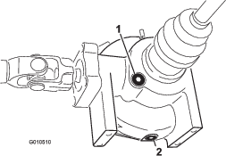
Position the machine on a level surface.
-
Clean the area around the dipstick (Figure 19).
-
Unscrew the dipstick from the top of the transaxle and wipe it with a clean rag.
-
Screw the dipstick into the transaxle and ensure that it is fully seated.
-
Unscrew the dipstick and check the fluid level.
Note: The fluid should be up to top of the flat portion of the dipstick.
-
If the level is low, add enough of the specified fluid to achieve the proper level.
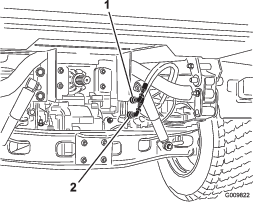
Checking the High Flow Hydraulic-fluid Level (TC models only)
| Maintenance Service Interval | Maintenance Procedure |
|---|---|
| Before each use or daily |
|
Hydraulic-fluid type:Toro Premium All Season Hydraulic Fluid (Available in 5 gallon pails or 55 gallon drums. See parts catalog or Toro distributor for part numbers.)
Alternate fluids: If the Toro fluid is not available, another conventional petroleum–based fluid may be used provided it meets the following material properties and industry specifications. Consult with your lubricant distributor to identify a satisfactory product.
Note: Toro will not assume responsibility for damage caused by improper substitutions, so use only products from reputable manufacturers who will stand behind their recommendation.
High Viscosity Index/Low Pour Point Antiwear Hydraulic Fluid, ISO VG 46
Material Properties:
-
Viscosity—ASTM D445 cSt @ 40ºC: 44 to 48/cSt @ 100ºC: 7.9 to 8.5
-
Viscosity Index, ASTM D2270—140 to 152
-
Pour Point, ASTM D97— -35ºF to -46ºF
-
FZG, Fail stage—11 or better
-
Water content (new fluid)—500 ppm (maximum)
Industry Specifications:
Vickers I-286-S, Vickers M-2950-S, Denison HF-0, Vickers 35 VQ 25 (Eaton ATS373-C)
-
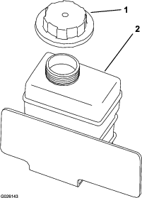
Clean the area around the filler neck and the cap of the hydraulic tank (Figure 20).
-
Remove the cap from the filler neck.
-
Remove the dipstick (Figure 20) from the filler neck and wipe it with a clean rag.
-
Insert the dipstick into the filler neck, then remove it and check the fluid level.
Note: The fluid level should be between the 2 marks on the dipstick.
-
If the level is low, add the appropriate fluid to raise the level to the upper mark; refer to Changing the High-flow Hydraulic fluid and Filter (TC models only).
-
Install the dipstick and cap onto the filler neck.
-
Start the engine and turn on the attachment.
Note: Let them run for about 2 minutes to purge air from the system.
Important: The machine must be running before starting the high-flow hydraulics.
-
Stop the engine and attachment and check for leaks.
Warning
Hydraulic fluid escaping under pressure can penetrate skin and cause injury.
-
Make sure all hydraulic fluid hoses and lines are in good condition and all hydraulic connections and fittings are tight before applying pressure to the hydraulic system.
-
Keep your body and hands away from pin hole leaks or nozzles that eject high pressure hydraulic fluid.
-
Use cardboard or paper to find hydraulic leaks.
-
Safely relieve all pressure in the hydraulic system before performing any work on the hydraulic system.
-
Seek immediate medical attention if fluid is injected into your skin.
-
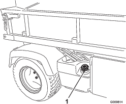
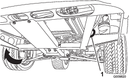
Checking the Front-differential-oil Level (4-wheel drive models only)
| Maintenance Service Interval | Maintenance Procedure |
|---|---|
| Every 100 hours |
|
Differential-oil type: Mobil 424 hydraulic oil
-
Position the machine on a level surface.
-
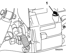
Clean the area around the fill/check plug on side of the differential (Figure 21).
-
Remove the fill/check plug and check the level of the oil.
Note: The oil should be up to hole.
-
If the oil is low, add specified oil.
-
Install the fill/check plug.
Checking the Torque of the Wheel Nuts
| Maintenance Service Interval | Maintenance Procedure |
|---|---|
| After the first 2 hours |
|
| After the first 10 hours |
|
| Every 200 hours |
|
Warning
Failure to maintain proper torque of the wheel nuts could result in failure or loss of a wheel and may result in personal injury.
Torque the front and rear wheel nuts to 109 to 122 N-m (80 to 90 ft-lb) after 1 to 4 hours of operation and again after 10 hours of operation. Torque every 200 hours thereafter.
Checking the Tire Pressure
| Maintenance Service Interval | Maintenance Procedure |
|---|---|
| Before each use or daily |
|
The air pressure in the front tires is 220 kPa (32 psi) and the rear tires is 124 kPa (18 psi).
Check the tire pressure frequently to ensure proper inflation. If the tires are not inflated to the correct pressure, the tires will wear prematurely.
Figure 22 is an example of tire wear caused by under inflation.

Figure 23 is an example of tire wear caused by over inflation.
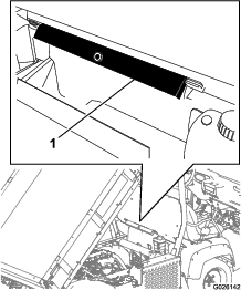
Checking the Brake-fluid Level
| Maintenance Service Interval | Maintenance Procedure |
|---|---|
| Before each use or daily |
|
| Every 1,000 hours |
|
Brake fluid type: DOT 3 brake fluid
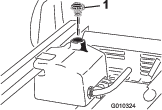
The brake-fluid reservoir is located under the dash.
-
Park the machine on a level surface.
-
The fluid level should be up to the Full line on the reservoir (Figure 24).
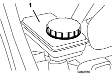
-
If the fluid level is low, clean the area around the cap, remove the reservoir cap, and fill the reservoir to the proper level with the specified brake fluid.
Note: Do not overfill the reservoir with brake fluid.
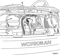
Note: You can remove the hood access to the reservoir from the front of the machine (Figure 25).
Starting the Engine
-
Sit on the operator’s seat and engage the parking brake.
-
Disengage the PTO and the high-flow hydraulics (if so equipped) and move the hand-throttle lever to the Off position (if equipped).
-
Move the shift lever to the Neutral position and press the clutch pedal.
-
Ensure that the hydraulic-lift lever is in the center position.
-
Keep your foot off of the accelerator pedal.
-
Insert the key into the ignition switch and rotate it clockwise to start the engine.
Note: Release key when engine starts.
Important: To prevent overheating of the starter motor, do not engage starter longer than 15 seconds. After 15 seconds of continuous cranking, wait 60 seconds before engaging the starter motor again.
Driving the Machine
-
Release the parking brake.
-
Fully press the clutch pedal.
-
Move the gear shift lever to first gear.
-
Release the clutch pedal smoothly while pressing the accelerator pedal.
-
When the machine gains enough speed, remove your foot from the accelerator pedal, fully press the clutch pedal, move the gear shift lever to the next gear and release the clutch pedal while pressing the accelerator pedal.
-
Repeat the procedure until the desired speed is attained.
Important: Always stop the machine before shifting to reverse from a forward gear or to a forward gear from reverse.
Note: Avoid long periods of engine idling.
Use the chart below to determine the ground speed of the vehicle at 3600 rpm.
Gear Range Ratio Speed (kmh) Speed (mph) 1 L 82.83 : 1 4.7 2.9 2 L 54.52 : 1 7.2 4.5 3 L 31.56 : 1 12.5 7.7 1 H 32.31 : 1 12.2 7.6 2 H 21.27 : 1 18.5 11.5 3 H 12.31 : 1 31.9 19.8 R L 86.94 : 1 4.5 2.8 R H 33.91 : 1 11.6 7.1 Important: Do not attempt to push or tow the machine to get it started. Damage to the drive train could result.
Stopping the Machine
To stop the machine, remove your foot from the accelerator pedal, press the clutch pedal, then press the brake pedal.
Stopping the Engine
To stop the engine, rotate the ignition key to the Off position and engage the parking brake. Remove the key from the switch to prevent accidental starting.
Breaking in a New Machine
To provide proper performance and long machine life, follow these guidelines for the first 100 operating hours.
-
Check the fluid and engine oil levels regularly and be alert for indications of overheating in any component of the machine.
-
After starting a cold engine, let it warm up for about 15 seconds before shifting into gear.
-
Avoid racing the engine.
-
To ensure optimum performance of the brake system, burnish (break–in) the brakes before use. To burnish the brakes, bring the vehicle up to full speed, apply the brakes to rapidly stop the vehicle without locking up the tires. Repeat this 10 times, waiting 1 minute between stops to avoid overheating the brakes. This is most effective if the machine is loaded with 454 kg (1000 lb).
-
Vary the machine speed during operation. Avoid excessive idling. Avoid fast starts and quick stops.
-
A break–in oil for the engine is not required. The original engine oil is the same type specified for regular oil changes.
-
Refer to the Maintenance section for any special low hour checks.
Checking the Safety-interlock System
| Maintenance Service Interval | Maintenance Procedure |
|---|---|
| Before each use or daily |
|
The purpose of the safety-interlock system is to prevent the engine from cranking or starting unless the clutch pedal is pressed.
Caution
If the safety-interlock switches are disconnected or damaged the machine could operate unexpectedly causing personal injury.
-
Do not tamper with the interlock switches.
-
Check the operation of the interlock switches daily and replace any damaged switches before operating the machine.
Note: Refer to Attachment Operator’s Manual for procedures on checking the attachment interlock system.
Verifying the Clutch Interlock Switch
-
Sit on the operator’s seat and engage the parking brake.
-
Move the shift lever to the Neutral position.
Note: The engine will not crank if the hydraulic-lift lever is locked in the forward position.
-
Without pressing the clutch pedal, rotate the ignition key clockwise to the Start position.
Note: If the engine cranks or starts, there is a malfunction in the interlock system that must be repaired before operating the machine.
Verifying the Hydraulic-lift Lever Interlock Switch
-
Sit on the operator’s seat and engage the parking brake.
-
Move the shift lever to the Neutral position and ensure that the hydraulic-lift lever is in the center position.
-
Press clutch pedal.
-
Move the hydraulic-lift lever forward and rotate the ignition key clockwise to the start position.
Note: If engine cranks or starts, there is a malfunction in the interlock system that must be repaired before operating the machine.
Ensuring Passenger Safety
Whenever you have a passenger riding in the machine, make sure he or she is wearing the seat belt and holding on securely. Drive slower and turn less sharply because your passenger does not know what you are going to do next and may not be prepared for turning, stopping, accelerating, and bumps.
You and your passenger should remain seated at all times, keeping arms and legs inside the vehicle. The operator should keep both hands on steering wheel, whenever possible, and the passenger should use the hand holds provided (Figure 26 and Figure 27).
Never allow passengers in the dump box or on any attachments. The vehicle is meant to have one driver and only one passenger—no more.
Ensuring Proper Speed
Speed is one of the most important variables leading to accidents. Driving too fast for the conditions can cause you to lose control and have an accident. Speed can also make a minor accident worse. Driving head on into a tree at slow speed can cause injury and damage, but, driving into a tree at high speed can destroy the vehicle and kill you and your passenger.
Never drive too fast for the conditions. If there is any doubt about how fast to drive, slow down.
When using heavy attachments, more than 454 kg (1000 lb), such as sprayers, top dressers, or spreaders, etc., restrict your operating speed by moving the supervisor switch to the slow position.
Ensuring Proper Turning
Turning is another important variable leading to accidents. Turning too sharply for the conditions can cause the vehicle to lose traction and skid, or even tip over.
Wet, sandy, and slippery surfaces make turning more difficult and risky. The faster you are going, the worse this situation becomes so, slow down before turning.
During a sharp turn at higher speeds, the inside rear wheel may lift off of the ground. This is not a flaw in the design, it happens with most 4-wheel machine including passenger cars. If this happens, you are turning too sharply for the speed at which you are traveling. Slow down!
Ensuring Proper Braking
It is good practice to slow down before you get near an obstacle. This gives you extra time to stop or turn away. Hitting an obstacle can damage the machine and its contents. More important, it can injure you and your passenger. Gross machine weight has a major impact on your ability to stop and/or turn. Heavier loads and heavier attachments make a vehicle harder to stop or turn. The heavier the load, the longer it takes to stop.
The braking characteristics also change with no bed or attachment on the machine. Fast stops may cause the rear wheels to lock up before the front wheels lock up, which may affect the control of the machine. It is a good idea to decrease machine speed with no bed or attachment.
Turf and pavement are much slipperier when they are wet. It can take 2 to 4 times as long to stop on wet surfaces as on dry surfaces.
If you drive through standing water deep enough to get the brakes wet, they will not work well until they are dry. After driving through water, you should test the brakes to make sure they work properly. If they do not, drive slowly in first gear while putting light pressure on the brake pedal. This will dry the brakes out.
Do not downshift for braking on icy or slippery surfaces (wet grass) or while going down a hill because engine braking may cause skidding and loss of control. Shift to a lower gear before starting down a hill.
Preventing Tip Overs
The machine is equipped with a roll bar, hip restraints, seat belts, and hand hold. The Rollover Protection System (ROPS) used on the machine will reduce the risk of serious or fatal injury in the unlikely event of a tip over, although the system cannot protect the operator from all possible injuries.
Replace a damaged ROPS, do not repair or revise. Any alteration of the ROPS must be approved by the manufacturer.
The best way to prevent accidents involving utility machine is through continuous supervision and training of operators and paying constant attention to the area in which vehicle is being operated.
The best way for operators to prevent serious injury or death to themselves or others, is to familiarize themselves with the proper operation of the utility vehicle, to stay alert and to avoid actions or conditions which could result in a accident. In the event of a tip over, the risk of serious injury or death will be reduced if the operator is using the ROPS system and seat belts and is following the instructions provided.
Operating on Hills
Warning
Tipping or rolling the machine on a hill could cause serious personal injury.
-
Do not operate the vehicle on steep slopes.
-
If engine stalls or you lose headway on a hill, never attempt to turn vehicle around.
-
Always back straight down a hill in reverse gear.
-
Never back down in neutral or with the clutch depressed, using only the brakes.
-
Never drive across a steep hill, always drive straight up or down.
-
Avoid turning on a hill.
-
Don’t “drop the clutch” or slam on the brakes. Sudden speed change can initiate a tip over.
Use extra care when on hills. Never go on hills that are extremely steep. Stopping while going down a hill will take longer than on level ground. Turning while going up or down a hill is more dangerous than turning on the level. Turns while going down hill, especially with the brakes on, and, turning up hill while traversing a hill are particularly dangerous. Even at a slow speed and without a load, tip overs are more likely if you turn on a hill.
Slow down and shift into a lower gear before starting up or down a hill. If you have to turn while on a hill, do it as slowly and cautiously as possible. Never make sharp or fast turns on a hill.
If you stall or begin to lose headway while climbing a steep hill, quickly apply the brakes, shift to neutral, start the engine and shift to reverse. At idle speed, the engine and transaxle drag will aid the brakes in controlling the vehicle on the hill and help you back down the hill more safely.
Reduce the weight of the load if it is a steep hill or if the load has high center of gravity. Remember, loads can shift, secure them.
Note: The machine has excellent hill-climbing ability. The differential lock will increase this ability. Hill climbing traction can also be increased by adding weight to the rear of the vehicle in one of the following ways:
-
Adding weight to inside of box, making sure it is secured.
-
Mounting wheel weights to rear wheels.
-
Adding liquid ballast (calcium chloride) to rear tires.
-
Traction will increase with no passenger in front seat.
Loading and Dumping
The weight and position of the cargo and passenger can change the machine center of gravity and machine handling. To avoid loss of control resulting in personal injury, follow these guidelines.
Do not carry loads which exceed the load limits described on the machin-weight label.
Warning
The bed will lower whenever the dump lever is pushed down, even when the engine is off. Turning off the engine will not prevent the box from lowering. Always place the safety support on the extended lift cylinder to hold the box up if you are not going to lower it right away.
The machine has several combinations of boxes, platforms, and attachments available. These can be used in various combinations that allow for maximum capacity and versatility. The full sized box is 140 cm (55 inches) wide by 165 cm (65 inches) long and can hold up to 1477 kg (3249 lb) of evenly-distributed cargo.
Loads vary in how they are distributed. Sand spreads out evenly and quite low. Other items, such as bricks, fertilizer or landscape timbers, stack higher in the box.
The height and weight of the load has a significant influence on tip overs. The higher a load is stacked, the more likely the vehicle is to tip over. You may find that 1477 kg (3249 lb) stacks too high for safe operation. Reducing the total weight is one way to reduce the risk of a tip over. Distributing the load as low as possible is another way to reduce the risk of a tip over.
If the load is positioned toward one of the sides, it will make the machine much more likely to tip over on that side. This is especially true when turning if the load is on the outside of the turn.
Never position heavy loads behind the rear axle. If the load is positioned so far to the rear that it is behind the rear axle, it will reduce the weight on the front wheels and this will reduce steering traction. With the load all the way to the back, the front wheels can even come off of the ground when going over bumps or up a hill. This will result in a loss of steering and may lead to the machine tipping over.
As a general rule, position the weight of the load evenly from front to rear and evenly from side to side.
If a load is not secured, or you are transporting a liquid in a large container such as a sprayer, it can shift. This shifting happens most often while turning, going up or down hills, suddenly changing speeds, or while driving over rough surfaces. Shifting loads can lead to tip overs. Always secure loads so that they do not shift. Never dump the load while the machine is sideways on the hill.
Heavy loads increase stopping distance and reduce your ability to turn quickly without tipping over.
The rear cargo space is intended for load carrying purposes only, not for passengers.
Using the Differential Lock
The differential lock increases the machine traction by locking the rear wheels so one wheel will not spin out. This can help when you have heavy loads to haul on wet turf or slippery areas, going up hills, and on sandy surfaces. It is important to remember, however, that this extra traction is only for temporary limited use. Its use does not replace the safe operation, already discussed concerning steep hills and heavy loads.
The differential lock causes the rear wheels to spin at the same speed. When using differential lock your ability to make sharp turns is somewhat restricted and may scuff the turf. Use the differential lock only when needed, at slower speeds and only in first or second gear.
Warning
Tipping or rolling the machine on a hill will cause serious injury.
-
The extra traction available with the differential lock can be enough to get you into dangerous situations such as climbing slopes that are too steep to turn around. Be extra careful when operating with the differential lock on, especially on steeper slopes.
-
If the differential lock is on when making a sharp turn at a higher speed and the inside rear wheel lifts off the ground, there may be a loss of control which could cause vehicle to skid. Use the differential lock only at slower speeds.
Using 4-wheel Drive (4-wheel drive models only)
The Automatic on Demand 4-wheel drive feature, on this vehicle does not require operator activation. The front wheel drive is not engaged (no power delivered to front wheels) until the rear wheels begin to lose traction. The bidirectional clutch senses the rear wheels slipping, engages the front wheel drive, and delivers power to the front wheels. The 4 wheel drive system continues to deliver power to the front wheels until the rear wheels have enough traction to move the vehicle without slipping. Once this occurs, the system stops delivering power to the front wheels and the handling characteristics become similar to that of a 2-wheel drive machine. The 4 wheel drive system functions in both froward and reverse, however, when turning the rear wheels will slip slightly more before power is delivered to the front wheels.
Warning
Tipping or rolling the machine on a hill will cause serious injury.
The extra traction available with the 4-wheel drive feature can be enough to get you into dangerous situations such as climbing slopes that are too steep to turn around. Be careful when operating, especially on steeper slopes.
Transporting the Machine
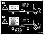
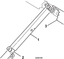
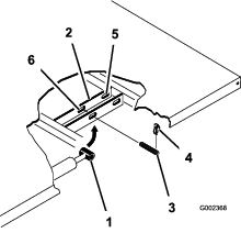
For moving the machine long distances, use a trailer. Make sure that the machine is secured to the trailer. Refer to Figure 28 and Figure 29 for the location of the tie-down points.
Important: Trailers weighing over 680 kg (1500 lb) are required to be equipped with trailer brakes.
Note: Load the machine on the trailer with the front of the machine facing forward. If that is not possible, secure the machine hood to the frame with a strap, or remove the hood and transport and secure it separately or the hood may blow off during transport.
Towing the Machine
In case of an emergency, the machine can be towed for a short distance. However, Toro does not recommend this as a standard procedure.
Warning
Towing at excessive speeds could cause the machine to lose steering control. Never tow the machine at faster than 8 kph (5 mph).
Towing the machine is a 2-person job. Affix a tow line to holes in the front frame member. Move the shifter to Neutral and release the parking brake. If the machine must be moved a considerable distance, transport it on a truck or trailer.
Note: The power steering will not function, making it difficult (increased effort) to steer.
Towing a Trailer with the Machine
The machine is capable of pulling trailers and attachments of greater weight than the machine itself.
Several types of tow hitches are available for the machine, depending on your application. Contact your Authorized Toro Distributor for details.
When equipped with a tow hitch bolted onto the rear axle tube, your machine can tow trailers or attachments with a Gross Trailer Weight (GTW) up to 1587 kg (3500 lb). Always load a trailer with 60% of the cargo weight in the front of the trailer. This places approximately 10% (272 kg (600 lb) max.) of the Gross Trailer Weight (GTW) on the tow hitch of the machine.
Trailer brakes are required whenever you tow a trailer over 680 kg (1500 lb) GTW is towed behind a machine.
When hauling cargo or towing a trailer (attachment), do not overload your machine or trailer. Overloading can cause poor performance or damage to the brakes, axle, engine, transaxle, steering, suspension, body structure, or tires.
Important: To reduce potential for drive line damage, use low range.
When towing fifth-wheel attachments, like a fairway aerator, always install the wheel bar (included with the fifth wheel kit) to prevent the front wheels from lifting off the ground if the towed attachments movement is suddenly impaired.
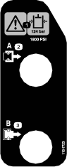
Using the Hydraulic Control
The hydraulic control supplies hydraulic power from the machine pump whenever the engine is running. The power can be used through the quick couplers at the rear of the machine.
Caution
Hydraulic fluid escaping under pressure can have sufficient force to penetrate skin and do serious damage. Care must be used when connecting or disconnecting hydraulic quick couplers. Stop the engine, apply the parking brake, lower the attachment, and place the remote hydraulic valve in the float detent position to relieve hydraulic pressure before connecting or disconnecting quick couplers.
Important: If multiple machines use the same attachment, cross contamination of the transmission fluid may occur. Change the transmission fluid more frequently
Using the Hydraulic-bed Lift Lever to Control Hydraulic Attachments
-
Off Position
This is the normal position for the control valve when it is not being used. In this position the work ports of the control valve are blocked and any load will be held by the check valves in both directions.
-
Raise (Quick Coupler “A” Position)
This is the position which will lift the bed, rear hitch attachment or apply pressure to quick coupler A. This also allows hydraulic fluid to return from quick coupler B to flow back into the valve and then out to the reservoir. This is a momentary position and when the lever is released it spring returns to the center Off position.
-
Lower (Quick Coupler B Position)
This position will lower the bed, rear hitch attachment, or apply pressure to quick coupler B. This also allows hydraulic fluid to return from quick coupler A to flow back into the valve and then out to the reservoir. This is a momentary position and when the lever is released it spring returns to the center off position. Momentarily holding and then releasing the control lever in this position will provide hydraulic fluid flow to quick coupler B which provides power down on the rear hitch. When released, it will hold the down pressure on the hitch.
Important: If used with a hydraulic cylinder, holding the control lever in the lower position causes the hydraulic-fluid flow to go over a relief valve which can damage the hydraulic system.
-
On Position
This position is similar to Lower (quick coupler B position). It also directs hydraulic fluid to quick coupler B except that the lever is held in this position by a detent lever in the control panel. This allows hydraulic fluid to flow continuously to equipment that uses a hydraulic motor. This position must only be used on attachments with a hydraulic motor attached.
Important: If used with a hydraulic cylinder or no attachment, the On position causes the hydraulic-fluid flow to go over a relief valve which can damage the hydraulic system. Use this position only momentarily or with a motor attached.
Important: Check hydraulic-fluid level after installation of an attachment. Check the operation of the attachment by cycling the attachment several times to purge air from system, then recheck hydraulic-fluid level. The attachment cylinder will slightly affect fluid level in the transaxle. Operation of vehicle with low hydraulic-fluid level can damage the pump, remote hydraulics, power steering, and the vehicle transaxle.
Connecting the Quick Couplers
Important: Clean dirt from quick couplers before connecting. Dirty couplers can introduce contamination into the hydraulic system
-
Pull back the locking ring on the coupler.
-
Insert the hose nipple into the coupler until it snaps into position.
Note: When attaching remote equipment to the quick couplers, determine which side requires pressure, then attach that hose to quick coupler B, which will have pressure when the control lever is pushed forward or locked in the On position.
Disconnecting the Quick Couplers
Note: With both the vehicle and attachment turned off, move the lift lever back and forth to remove the system pressure and ease the disconnection of the quick couplers.
-
Pull back the locking ring on the coupler.
-
Pull the hose firmly from the coupler.
Important: Clean and install the dust plug and dust covers to the quick coupler ends when not in use.
Troubleshooting the Hydraulic Control
-
Difficulty in connecting or disconnecting quick couplers.
The pressure not relieved (the quick coupler is under pressure).
-
The power steering is turning with great difficulty or it is not turning at all.
-
The hydraulic-fluid level is low.
-
The hydraulic-fluid temperature is hot.
-
The pump is not operating.
-
-
There are hydraulic leaks.
-
The fittings are loose.
-
The fitting is missing the o-ring.
-
-
An attachment does not function.
-
The quick couplers are not fully engaged.
-
The quick couplers are interchanged.
-
-
There is a squealing noise.
-
Remove the valve left in the On detent position causing hydraulic fluid to flow over the relief valve.
-
The belt is loose.
-
-
The engine will not start.
The hydraulic lever is locked in forward position
Maintenance
Determine the left and right sides of the machine from the normal operating position.
Caution
Only qualified and authorized personnel shall be permitted to maintain, repair, adjust, or inspect the machine.
Avoid fire hazards and have fire protection equipment present in the work area. Do not use an open flame to check level or leakage of fuel, battery electrolyte, or coolant. Do not use open pans of fuel or flammable cleaning fluids for cleaning parts.
Caution
If you leave the key in the ignition switch, someone could accidently start the engine and seriously injure you or other bystanders.
Remove the key from the ignition before you do any maintenance.
Recommended Maintenance Schedule(s)
| Maintenance Service Interval | Maintenance Procedure |
|---|---|
| After the first 2 hours |
|
| After the first 10 hours |
|
| After the first 50 hours |
|
| Before each use or daily |
|
| Every 25 hours |
|
| Every 50 hours |
|
| Every 100 hours |
|
| Every 200 hours |
|
| Every 400 hours |
|
| Every 600 hours |
|
| Every 800 hours |
|
| Every 1,000 hours |
|
Operating in Adverse Conditions
Important: If the machine is subjected to any of the conditions listed below, maintenance should be performed twice as frequently:
-
Desert operation
-
Cold climate operation below 0° C (32° F)
-
Trailer towing
-
Frequent operation on dusty roads
-
Construction work
-
After extended operation in mud, sand, water, or similar dirty conditions, have your brakes inspected and cleaned as soon as possible. This will prevent any abrasive material from causing excessive wear.
Pre-Maintenance Procedures
Many of the subjects covered in this maintenance section require raising and lowering the bed. The following precautions must be taken or serious injury or death could result.
Warning
Before servicing or making adjustments to the machine, stop engine, set parking brake, and remove the key from the ignition switch. Remove any load material from the bed or other attachment before working under a raised bed. Never work under a raised bed without positioning the safety support on a fully extended cylinder rod.
Using the Bed Support
Important: Always install or remove the bed support from the outside of the bed.
-
Raise the bed until the lift cylinders are fully extended.
-
Remove the bed support from the storage brackets on back of the ROPS panel (Figure 31).
-
Push the bed support onto the cylinder rod, making sure that the support end tabs rest on the end of cylinder barrel, and on the cylinder rod end (Figure 32).
-
Remove the bed support from the cylinder and insert it into the brackets on the back of the ROPS panel.
Caution
Do not try to lower bed with bed safety support on cylinder.
Removing the Full Bed
-
Start the engine, engage the hydraulic-lift lever, and lower the bed until the cylinders are loose in the slots.
-
Release the lift lever and turn off the engine.
-
Remove the lynch pins from the outer ends of the cylinder rod clevis pins (Figure 33).
-
Remove the clevis pins securing the cylinder rod ends to the bed-mounting plates by pushing the pins towards the inside (Figure 33).
-
Remove the lynch pins and clevis pins securing the pivot brackets to the frame channels (Figure 33).
-
Lift the bed off of the machine.
Caution
The full bed weighs approximately 148 kg (325 lb), so do not try to install or remove it by yourself. Use an overhead hoist or get the help of 2 or 3 other people.
-
Store the cylinders in the storage clips.
-
Engage the hydraulic lift-lock lever on the machine to prevent accidental extension of the lift cylinders.
Installing the Full Bed
Note: If the bed sides will be installed on the flat bed, it is easier to install them before installing the bed on the machine.
Note: Ensure that the rear pivot plates are bolted to the bed frame/channel so that lower end angles to the rear (Figure 34).
Caution
The full bed weighs approximately 148 kg (325 lb), so do not try to install or remove it by yourself. Use an overhead hoist or get the help of 2 or 3 other people.
Note: Ensure that the spacer brackets and wear blocks (Figure 35) are installed with the carriage bolt heads positioned inside the machine.
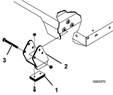
-
Ensure that the lift cylinders are fully retracted.
-
Carefully set the bed onto the machine frame aligning the rear bed pivot-plate holes with the holes in the rear frame channel and install 2 clevis pins and lynch pins (Figure 35).
-
With the bed lowered, secure each cylinder rod end, to the appropriate slots in the bed-mounting plates with a clevis pin and lynch pin.
-
Insert the clevis pin from outside of the bed with the lynch pin toward the outside (Figure 35).
Note: The rear slots are for a full bed installation and front slots are for a 2/3 bed installation.
Note: The engine may need to be started to extend or retract the cylinders for alignment with the holes.
Note: The unused slot can be plugged with a bolt and nut to prevent assembly errors.
-
Start the engine and engage the hydraulic lift lever to raise the bed.
-
Release the lift lever and turn off the engine.
-
Install the bed safety support to prevent accidental lowering of the bed; refer to Using the Bed Support.
-
Install the lynch pins to the inside ends of the clevis pins.
Note: If the automatic tail gate release has been installed on the bed, ensure that the front dump link rod has been placed on the inside of the left side clevis pin before the lynch pin is installed.
Raising the Machine
Danger
A machine on a jack may be unstable and slip off of the jack, injuring anyone beneath it.
-
Do not start the machine while the machine is on a jack.
-
Always remove the key from the switch before getting off of the machine.
-
Block the tires when the machine is on a jack.
-
Do not start the engine while the machine is on a jack, because the engine vibration or wheel movement could cause the machine to slip off of the jack.
-
Do not work under the machine without jack stands supporting it. The machine could slip off a jack, injuring anyone beneath it.
-
When jacking up the front of the vehicle, always place a 2 x 4 block (or similar material) between the jack and the machine frame.
-
The jacking point at the front of the machine is under the front center frame support (Figure 36) and at the rear it is under the axle (Figure 37).
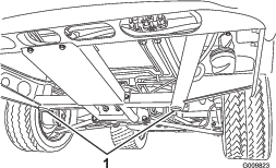
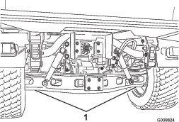
Removing the Hood
-
While grasping the hood in the headlight openings, lift up on the hood to release the lower mounting tabs from the frame slots (Figure 38).
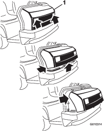
-
Pivot the bottom of the hood upward until the top mounting tabs can be pulled from the frame slots (Figure 38).
-
Pivot the top of the hood forward, and unplug the wire connectors from the head lights (Figure 38).
-
Remove the hood.
Installing the Hood
-
Connect the lights.
-
Insert the top mounting tabs into the frame slots.
-
Insert the lower mounting tabs into the frame slots.
-
Ensure that the hood is fully engaged in the top, sides and bottom grooves.
Lubrication
Greasing the Bearings and Bushings
| Maintenance Service Interval | Maintenance Procedure |
|---|---|
| Every 100 hours |
|
The machine has grease fittings that must be lubricated regularly with No. 2 General Purpose Lithium-Base Grease.
The grease fitting locations and quantities are as follows:
-
Ball joints (4), tie rods (2), pivot mounts (2) and steering cylinder (2) (Figure 39)
-
Spring tower (2) (Figure 40)
-
Clutch (1) and brake (1) (Figure 41)
-
U-joint (18) and 4 wheel drive shaft (3) (Figure 42)
Important: When greasing the drive shaft universal shaft bearing crosses, pump grease until it comes out of all 4 cups at each cross.
-
Wipe each grease fitting clean so foreign matter cannot be forced into the bearing or bushing.
-
Pump grease into each bearing or bushing.
-
Wipe off excess grease.
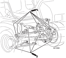
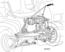
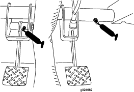
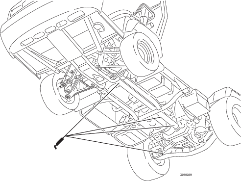
Engine Maintenance
Servicing the Air Cleaner
| Maintenance Service Interval | Maintenance Procedure |
|---|---|
| Every 25 hours |
|
| Every 200 hours |
|
Inspect the air cleaner and hoses periodically to maintain maximum engine protection and to ensure maximum service life. Check the air-cleaner body for damage which could possibly cause an air leak. Replace a damaged air-cleaner body.
Inspect and change the air-cleaner filter as described in the following procedure:
-
Release the latches on the air cleaner and pull the air-cleaner cover off the air-cleaner body (Figure 43).
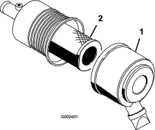
-
Squeeze the dust cap sides to open it and knock the dust out.
-
Gently slide the filter out of the air-cleaner body (Figure 43).
Note: Avoid knocking the filter into the side of the body.
Note: Do not attempt to clean the filter.
-
Inspect the new filter for damage by looking into the filter while shining a bright light on the outside of the filter.
Note: Holes in the filter will appear as bright spots.Inspect the element for tears, an oily film, or damage to the rubber seal. If the filter is damaged do not use it.To prevent engine damage, always operate the engine with the air filter and cover installed.Take special care to keep particulates from dropping into the clean areas of the air filter housing.
-
Carefully slide the filter over the body tube (Figure 43).
Note: Ensure that it is fully seated by pushing on the outer rim of the filter while installing it.
-
Install the air-cleaner cover with the side facing up, and secure the latches (Figure 43).
Changing the Engine Oil and Filter
| Maintenance Service Interval | Maintenance Procedure |
|---|---|
| After the first 50 hours |
|
| Every 200 hours |
|
Engine-oil quantity: 3.2 L (3.4 US qt) (with a filter)
Engine-oil type: Detergent engine oil API SJ or higher
Engine-oil viscosity: 10W-30; Choose an engine-oil viscosity according to the ambient-air temperature to the table in Figure 44.
-
Raise the bed (if equipped), and place the safety support on the extended-lift cylinder to hold up the bed.
-
Remove the drain plug and let the oil flow into a drain pan (Figure 45).
-
When the oil stops, install the drain plug.
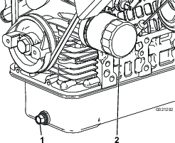
-
Remove the oil filter (Figure 45).
-
Apply a light coat of clean oil to the new filter seal before screwing it on.
-
Screw the filter on until the gasket contacts the mounting plate, then tighten the filter 1/2 to 2/3 of a turn.
Note: Do not overtighten.
-
Add the specified oil to the crankcase; refer to Checking the Engine-oil Level.
Replacing the Spark Plug
| Maintenance Service Interval | Maintenance Procedure |
|---|---|
| Every 400 hours |
|
The spark plug usually lasts a long time; however, the plug should be removed and checked whenever the engine malfunctions, or every 400 hours. Replace the spark plug to ensure proper engine performance and reduce exhaust emission level.
The correct spark plug to use is an NGK-R BKR5E.
The recommended air gap is 0.81 mm (0.032 inch).
-
Clean the area around the spark plugs, so that foreign matter cannot fall into the cylinder when you remove the spark plug.
-
Pull wires off of the spark plugs and remove the plugs from the cylinder head.
-
Check the condition of the side electrode, center electrode, and the center electrode insulator to ensure that there is no damage.
Important: A cracked, fouled, dirty, or otherwise malfunctioning spark plug must be replaced. Do not sand blast, scrape, or clean electrodes by using a wire brush because grit may eventually release from the plug and fall into the cylinder. The result is usually a damaged engine.
-
For each spark plug, set the air gap between the center and side electrodes to 0.81 mm (0.032 inch).
-
Install the correctly gapped spark plugs and tighten each one to 24.5 to 29 N-m (18 to 22 ft-lb).
-
Install the spark-plug wires.
Fuel System Maintenance
Replacing the Fuel Filter
| Maintenance Service Interval | Maintenance Procedure |
|---|---|
| Every 400 hours |
|
-
Raise the bed (if equipped), and place the safety support on the extended-lift cylinder to hold up the bed.
-
Unplug the wiring-harness connectors from the fuel pump (Figure 47).
-
Loosen the hose clamp and disconnect the fuel line from the fuel-pump cap (Figure 47).
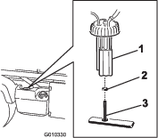
-
Remove the fuel-pump cap from the top of the fuel tank (Figure 47).
Note: Do not allow the fuel-pump assembly to rotate in the tank while removing the fuel pump. Damage to the float assembly can occur if the fuel pump rotates inside the fuel tank.
-
Remove the fuel-pump assembly and the fuel filter from the tank (Figure 47).
-
Remove the clamp securing the fuel filter hose to the fuel-pump fitting.
-
Remove the hose from the fitting (Figure 47).
-
Insert the new hose clamp onto the new fuel-filter hose.
-
Insert the hose onto the fuel pump and secure the clamp.
-
Insert the assembly into the fuel tank, and tighten the cap to 20 to 22 N-m (175 to 200 in-lb).
-
Connect the wires and secure the hose with the hose clamp.
Inspecting the Fuel Lines and Connections
| Maintenance Service Interval | Maintenance Procedure |
|---|---|
| Every 400 hours |
|
| Every 1,000 hours |
|
Inspect the fuel lines and connections for deterioration, damage, or loose connections.
Electrical System Maintenance
Servicing the Fuses

Jump Starting the Machine
Warning
Jump starting can be dangerous. To avoid personal injury or damage to electrical components in machine, observe the following warnings:
-
Never jump start with a voltage source greater than 15 volts DC This will damage the electrical system.
-
Never attempt to jump start a discharged battery that is frozen. It could rupture or explode during jump starting.
-
Observe all battery warnings while jump starting your machine.
-
Be sure your machine is not touching the jump start machine.
-
Connecting cables to the wrong post could result in personal injury and/or damage to the electrical system.
-
Squeeze the battery cover to release the tabs from battery base, and remove the battery cover from the battery base (Figure 50).
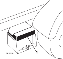
-
Connect a jumper cable between the positive posts of the 2 batteries (Figure 51). The positive post may be identified by a + sign on top of the battery cover.
-
Connect one end of the other jumper cable to the negative terminal of the battery in the other machine.
Note: The negative terminal has NEG on the battery cover.
Note: Do not connect the other end of the jumper cable to the negative post of the discharged battery. Connect the jumper cable to the engine or frame. Do not connect the jumper cable to the fuel system.
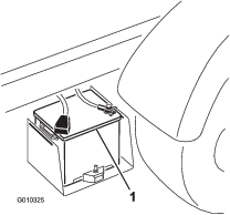
-
Start the engine in the machine providing the jump start.
Note: Let it run a few minutes, then start your engine.
-
Remove the negative jumper cable first from your engine, then the battery in the other machine.
-
Install the battery cover to the battery base.
Servicing the Battery
| Maintenance Service Interval | Maintenance Procedure |
|---|---|
| Every 50 hours |
|
Danger
Battery electrolyte contains sulfuric acid which is a deadly poison and causes severe burns.
-
Do not drink electrolyte and avoid contact with skin, eyes or clothing. Wear safety glasses to shield your eyes and rubber gloves to protect your hands.
-
Fill the battery where clean water is always available for flushing the skin.
-
Keep the battery-electrolyte level properly maintained.
-
Keep the top of the battery clean by washing it periodically with a brush dipped in ammonia or bicarbonate of soda solution. Flush the top surface with water after cleaning. Do not remove the fill cap while cleaning.
-
Ensure that the battery cables are kept tight on the terminals to provide good electrical contact.
-
If corrosion occurs at terminals, remove the battery cover, disconnect the cables (negative (–) cable first), and scrape the clamps and terminals separately. Reconnect the cables (positive (+) cable first) and coat the terminals with petroleum jelly.
-
Maintain cell electrolyte level with distilled or demineralized water. Do not fill the cells above the bottom of the fill ring inside each cell.
-
If you store the machine in a location where temperatures are extremely high, the battery will run down more rapidly than if the machine is stored in a location where temperatures are cool.
Drive System Maintenance
Changing the Front-differential Oil (4-wheel drive models only)
| Maintenance Service Interval | Maintenance Procedure |
|---|---|
| Every 800 hours |
|
Differential-oil specification: Mobil 424 hydraulic oil
-
Position the machine on a level surface, stop the engine, set the parking brake and remove the key from the ignition switch.
-
Clean the area around the drain plug on the side of the differential (Figure 52).
-
Place a drain pan under the drain plug.
-
Remove the drain plug and let the oil flow into the drain pan.
-
Install and tighten the plug when the oil stops draining.
-
Clean the area around the fill/check plug on the bottom of the differential.
-
Remove the fill/check plug and add specified oil until the oil level is up to the hole.
-
Install the fill/check plug.
Inspecting the Constant-velocity Boot (4-wheel drive models only)
| Maintenance Service Interval | Maintenance Procedure |
|---|---|
| Every 200 hours |
|
Inspect the constant-velocity boot for cracks, holes, or a loose clamp. Contact your Authorized Toro Distributor for repair if you find any damage.
Adjusting the Shift Cables
| Maintenance Service Interval | Maintenance Procedure |
|---|---|
| After the first 10 hours |
|
| Every 200 hours |
|
-
Move the shift lever to the Neutral position.
-
Remove the clevis pins securing the shift cables to the transaxle-shift arms (Figure 53).
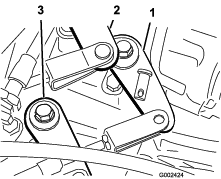
-
Loosen the clevis jam nuts and adjust each clevis, so that the cable free play is equal forward and backward relative to the hole in the transaxle-shift arm (with the transaxle lever free play taken up in the same direction).
-
Install the clevis pins and tighten the jam nuts when finished.
Adjusting the High–Low Cable
| Maintenance Service Interval | Maintenance Procedure |
|---|---|
| Every 200 hours |
|
-
Remove the clevis pin securing the High–Low cable to the transaxle (Figure 53).
-
Loosen the clevis jam nut and adjust the clevis so that the clevis hole aligns with the hole in the transaxle bracket.
-
Install the clevis pin and tighten the jam nut when finished.
Adjusting Differential-lock Cable
| Maintenance Service Interval | Maintenance Procedure |
|---|---|
| Every 200 hours |
|
-
Move the differential-lock lever to the Off position.
-
Loosen the jam nuts securing the differential-lock cable to the bracket on the transaxle (Figure 54).
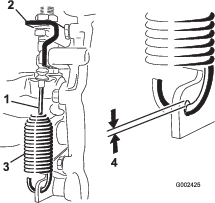
-
Adjust the jam nuts to obtain a 0.25 to 1.5 mm (0.01 to 0.06 inch) gap between the spring hook and the OD of the hole in the transaxle lever.
-
Tighten the jam nuts when finished.
Inspecting the Tires
| Maintenance Service Interval | Maintenance Procedure |
|---|---|
| Every 100 hours |
|
Operating accidents, such as hitting curbs, can damage a tire or rim and also disrupt wheel alignment, so inspect the tire condition after an accident.
Check the tire pressure frequently to ensure proper inflation. If the tires are not inflated to the correct pressure, the tires will wear prematurely.
Figure 55 is an example of tire wear caused by under inflation.
Figure 56 is an example of tire wear caused by over inflation.
Checking the Front-wheel Alignment
| Maintenance Service Interval | Maintenance Procedure |
|---|---|
| Every 400 hours |
|
-
Make sure the tires are facing straight ahead.
-
Measure the center-to-center distance (at axle height) at the front and rear of the steering tires (Figure 57).
Note: The measurement must be within 0 ± 3 mm (0 ± 0.12 inch) at the front of the tire then at the rear of the tire. Rotate the tire 90° and check the measurement.
Important: Check the measurements at consistent locations on the tire. The machine should be on a flat surface with the tires facing straight ahead.
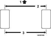
-
Adjust the center-to-center distance as follows:
-
Loosen the jam nut at the center of the tie rod (Figure 58).
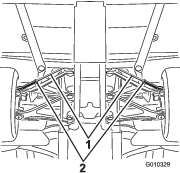
-
Rotate the tie rod to move the front of the tire inward or outward to achieve the center to center distances from front to back.
-
Tighten the tie rod jam nut when the adjustment is correct.
-
Check to ensure that the tires turn an equal amount to the right and to the left.
Note: If the tires do not turn equally, refer to the Service Manual for the adjustment procedure.
-
Cooling System Maintenance
Removing Debris from the Cooling System
| Maintenance Service Interval | Maintenance Procedure |
|---|---|
| Before each use or daily |
|
-
Turn the engine off and clean the engine area thoroughly of all debris.
-
Unlatch and remove the radiator screen from the front of the radiator (Figure 59).
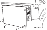
-
If so equipped, rotate the latches and pivot the oil cooler away from the radiator (Figure 60).
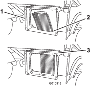
-
Clean the radiator, oil cooler, and screen thoroughly with compressed air.
Note: Blow debris away from the radiator. Do not use water to clean external surfaces of the radiator.
-
Install the cooler and screen to the radiator.
Changing the Engine Coolant
| Maintenance Service Interval | Maintenance Procedure |
|---|---|
| Every 1,000 hours |
|
Coolant type: 50/50 mixture of water and permanent ethylene-glycol antifreeze
-
Park the machine on a level surface.
-
Raise the bed (if so equipped) and place the safety support on the extended-lift cylinder to hold up the bed.
Caution
If the engine has been running, the pressurized, hot coolant can escape and cause burns.
-
Do not open the reserve tank cap when the engine is running.
-
Allow engine to cool at least 15 minutes or until the reserve tank cap is cool enough to touch without burning your hand.
-
Use a rag when opening the reserve tank cap , and open the cap slowly to allow steam to escape.
-
-
Remove the radiator cap.
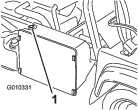
-
Remove the reserve-tank cap (Figure 62).
-
Disconnect the lower radiator hose and allow coolant to flow into a drain pan.
-
When coolant stops, connect the lower radiator hose.
-
Remove the coolant-drain plug from the engine and allow coolant to flow into a drain pan.
-
When coolant stops, install the drain plug.
-
Slowly fill the radiator with a 50/50 mixture of water and permanent ethylene-glycol antifreeze
-
Install the radiator cap.
-
Fill the reservoir tank to the bottom of the filler neck.
-
Start the engine and allow it to idle.
-
As air escapes, fill the reservoir to the bottom of the filler neck.
Note: Do not allow the engine to heat up to the running temperature.
-
Install the reservoir-tank cap.
-
Run the machine until it reaches the operating temperature.
-
Turn off the machine and allow it to cool.
-
Check the coolant level again, and replenish it, if required.
Brake Maintenance
Adjusting the Parking Brake
| Maintenance Service Interval | Maintenance Procedure |
|---|---|
| After the first 10 hours |
|
| Every 200 hours |
|
-
Remove the rubber grip from the parking-brake lever (Figure 63).
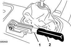
-
Loosen the set screw securing the knob to the parking brake lever (Figure 64).
-
Rotate the knob until a force of 20 to 22 kg (45 to 50 lb) is required to actuate the lever.
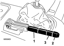
-
Tighten the set screw when finished.
Note: If no adjustment is left at the handle, loosen the handle to the middle of the adjustment and adjust the cable at the rear, then repeat step 3.
-
Install the rubber grip onto the parking-brake lever.
Adjusting the Brake Pedal
| Maintenance Service Interval | Maintenance Procedure |
|---|---|
| Every 200 hours |
|
Note: Remove the font hoot to ease the adjustment procedure.
-
Remove the cotter pin and clevis pin securing the master cylinder yoke to the brake-pedal pivot (Figure 65).
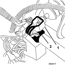
-
Lift up on the brake pedal (Figure 66) until it contacts the frame.
-
Loosen the jam nuts securing the yoke to the master cylinder shaft (Figure 66).
-
Adjust the yoke until its holes align with the hole in the brake-pedal pivot.
-
Secure the yoke to the pedal pivot with the clevis pin and cotter pin.
-
Tighten the jam nuts securing the yoke to the master cylinder shaft.
Note: The brake master cylinder must relieve pressure when properly adjusted.
Belt Maintenance
Adjusting the Alternator Belt
| Maintenance Service Interval | Maintenance Procedure |
|---|---|
| After the first 10 hours |
|
| Every 200 hours |
|
-
Raise the bed (if so equipped) and position the safety support on the extended-lift cylinder to hold up the bed.
-
Check the tension by pressing the belt at mid span between the crankshaft and alternator pulleys with 10 kg (22 lb) of force (Figure 67).
Note: A new belt should deflect 8 to 12 mm (0.3 to 0.5 inch).
Note: A used belt should deflect 10 to 14 mm (0.4 to 0.55 inch). If the deflection is incorrect, proceed to the next step. If correct, continue operation.
-
To adjust belt tension, complete the following:
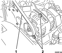
Controls System Maintenance
Adjusting the Clutch Pedal
| Maintenance Service Interval | Maintenance Procedure |
|---|---|
| Every 200 hours |
|
Note: You can adjust the clutch-pedal cable at the bell housing or at the clutch-pedal pivot. The front hood can be removed to ease the access to the pedal pivot.
-
Loosen the jam nuts securing the clutch cable to the bracket on the bell housing (Figure 68).
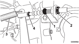
Note: You may remove and rotate the ball joint, if additional adjustment is required.
-
Disconnect the return spring from the clutch lever.
-
Adjust the jam nuts or ball joint until the back, rear edge of the clutch pedal is 9.5 ± 0.3 cm (3.75 ± 0.12 inch) from the top of the floor plate diamond pattern, when an 1.8 kg (4 lb) force is applied to the pedal (Figure 69).
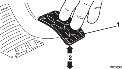
Note: Force is applied so the clutch release bearing lightly contacts the pressure plate fingers.
-
Tighten the jam nuts after the adjustment has been attained.
-
Check the 9.5 ± 0.3 cm (3.75 ± 0.12 inch) dimension after the jam nuts have been tightened to ensure proper adjustment.
Note: Adjust again if it is necessary.
-
Connect the return spring to the clutch lever.
Important: Ensure that the rod end is positioned squarely on the ball, not twisted, and remains parallel to the clutch pedal after the jam nut is tightened (Figure 70).
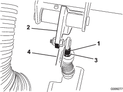
Note: The clutch free play should never be less than 19 mm (0.75 inch).
Converting the Speedometer
You can convert the speedometer from mph to km/h or km/h to mph.
-
Position the machine on a level surface, stop the engine, engage the parking brake, and remove the key from the ignition switch.
-
Remove the hood; refer to Removing the Hood.
-
Locate the 2 loose wires next to the speedometer.
-
Remove the connector plug from the harness wire and connect the wires together.
Note: The speedometer will switch to km/h or mph.
-
Install the hood.
Hydraulic System Maintenance
Changing the Hydraulic fluid and Cleaning the Strainer
| Maintenance Service Interval | Maintenance Procedure |
|---|---|
| Every 800 hours |
|
Hydraulic-fluid capacity: approximately 7 L (7.5 US qt)
Hydraulic-fluid type: Dexron III ATF
-
Position the machine on a level surface, stop the engine, engage the parking brake, and remove the key from the ignition switch.
-
Remove the drain plug from the side of the reservoir, and let the hydraulic fluid flow into a drain pan (Figure 71).
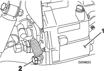
-
Note the orientation of the hydraulic hose and 90° fitting connected to the strainer on the side of the reservoir (Figure 72).
-
Remove the hydraulic hose and 90° fitting.
-
Remove the strainer and clean it by back flushing it with a clean de-greaser.
Note: Allow it to air dry before installing.
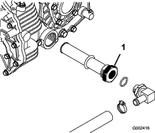
-
Install the strainer.
-
Install the hydraulic hose and 90° fitting to the strainer in the same orientation.
-
Install and tighten the drain plug.
-
Fill the reservoir with approximately 7 L (7.5 US qt) of the specified hydraulic fluid; refer to Checking the Transaxle/Hydraulic-fluid Level.
-
Start the engine and operate the machine to fill the hydraulic system.
-
Check the hydraulic fluid level and replenish it, if required.
Important: Use only the hydraulic fluid specified. Other fluids could cause system damage.
Replacing the Hydraulic Filter
| Maintenance Service Interval | Maintenance Procedure |
|---|---|
| After the first 10 hours |
|
| Every 800 hours |
|
Important: Use of any other filter may void the warranty on some components.
-
Position the machine on a level surface, stop the engine, engage the parking brake, and remove the key from ignition switch.
-
Clean the area around filter mounting area.
-
Place a drain pan under the filter and remove the filter (Figure 73).
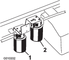
-
Lubricate the gasket on the new filter.
-
Ensure that the filter mounting area is clean.
-
Screw the filter on until the gasket contacts the mounting plate, and tighten the filter 1/2 turn.
-
Start the engine and let it run for about 2 minutes to purge air from the system.
-
Stop the engine and check the hydraulic-fluid level and for leaks.
Changing the High-flow Hydraulic fluid and Filter (TC models only)
| Maintenance Service Interval | Maintenance Procedure |
|---|---|
| After the first 10 hours |
|
| Every 800 hours |
|
Hydraulic-fluid capacity: approximately 15 L (4 US gallons)
Hydraulic-fluid type:Toro Premium All Season Hydraulic Fluid (Available in 5 gallon pails or 55 gallon drums. See parts catalog or Toro distributor for part numbers.)
Alternate fluids: If the Toro fluid is not available, another conventional petroleum–based fluid may be used provided it meets the following material properties and industry specifications. Consult with your lubricant distributor to identify a satisfactory product.
Note: Toro will not assume responsibility for damage caused by improper substitutions, so use only products from reputable manufacturers who will stand behind their recommendation.
High Viscosity Index/Low Pour Point Antiwear Hydraulic Fluid, ISO VG 46
Material Properties:
-
Viscosity—ASTM D445 cSt @ 40ºC: 44 to 48/cSt @ 100ºC: 7.9 to 8.5
-
Viscosity Index, ASTM D2270—140 to 152
-
Pour Point, ASTM D97— -35ºF to -46ºF
-
FZG, Fail stage—11 or better
-
Water content (new fluid)—500 ppm (maximum)
Industry Specifications:
Vickers I-286-S, Vickers M-2950-S, Denison HF-0, Vickers 35 VQ 25 (Eaton ATS373-C)
Note: Many hydraulic fluids are almost colorless, making it difficult to spot leaks. A red dye additive for the hydraulic system fluid is available in 20 ml (2/3 oz.) bottles. One bottle is sufficient for 15–22 1 (4–6 gal) of hydraulic fluid. Order part no. 44-2500 from your authorized Toro distributor.
Note: If the fluid becomes contaminated, contact your local Toro distributor because the system must be flushed. Contaminated fluid may look milky or black when compared to clean fluid. The service interval may need to be increased if using multiple attachments as the fluid may become contaminated quicker with the mixing of different hydraulic fluids.
-
Clean the area around the high-flow-filter mounting area (Figure 73).
-
Place a drain pan under the filter and remove the filter.
Note: If the fluid is not going to be drained, disconnect and plug the hydraulic line going to the filter.
-
Lubricate the new filter-sealing gasket and hand turn the filter onto the filter head until the gasket contacts the filter head. Then tighten it 3/4 turn further. The filter should now be sealed.
-
Fill the hydraulic reservoir with approximately 15 L (4 US gallons) of hydraulic fluid.
-
Start the machine and run it at idle for about 2 minutes to circulate the fluid and remove any air trapped in the system.
-
Stop the machine and check the fluid level.
-
Verify the fluid level.
-
Dispose of the fluid properly.
Raising the Cargo Box in an Emergency
The cargo box can be raised in an emergency without starting the engine by cranking starter or by jumping hydraulic system.
Raising the Cargo Box using the Starter
Crank the starter while holding the lift lever in the Raise position. Run the starter for 10 seconds, then wait 60 seconds before engaging the starter again. If the engine will not crank, you must remove the load and box (attachment) to service the engine or transaxle.
Raising the Cargo Box by Jumping the Hydraulic System
Caution
Before servicing or making adjustments to the machine, stop the engine, set the parking brake, and remove the key from the switch. Remove all load material that is loaded into the bed or other attachment before working under a raised bed. Never work under a raised bed without positioning the safety support on the fully extended cylinder rod.
2 hydraulic hoses, each with a male and female quick coupler, that fit the vehicle couplers are required to perform this operation.
-
Back another machine up to the rear of the disabled machine.
Important: The machine hydraulic system uses Dexron III ATF. To avoid system contamination, make sure the vehicle used to jump the hydraulic system uses an equivalent fluid.
-
On both machine, disconnect the 2 quick-coupler hoses from the hoses secured to the coupler bracket (Figure 74).
-
On the disabled machine, connect the 2 jumper hoses to the hoses that were disconnected (Figure 75).
-
Cap the unused fittings.
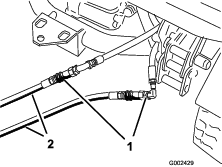
-
On the other machine, connect the 2 hoses to the coupler still in the coupler bracket (connect the top hose to the top coupler and the bottom hose to the bottom coupler) (Figure 76).
-
Cap the unused fittings.
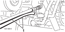
-
Keep all bystanders away from the machines.
-
Start the second machine, and move the lift lever to the raise position which will raise the disabled cargo box.
-
Move the hydraulic-lift lever to the neutral position, and engage the lift-lever lock.
-
Install the bed support onto the extended lift cylinder; refer to Using the Bed Support.
Note: With both the machine turned off, move the lift lever back and forth to remove the system pressure and ease the disconnection of the quick couplers.
-
After completing the operation, remove the jumper hoses and connect the hydraulic hoses to both machines.
Important: Check the hydraulic fluid levels, in both vehicles, before resuming operation.
Cleaning
Washing the Machine
The machine should be washed as needed. Use water alone or with a mild detergent. A rag may be used when washing the machine, however the hood will loose some of its luster.
Important: Do not use power washing equipment to wash the machine. Power washing equipment may damage the electrical system, loosen important decals, or wash away necessary grease at friction points. Avoid excessive use of water near the control panel, engine, and battery.
Important: Do not wash the machine with the engine running. Washing the machine with the engine running may result in internal engine damage.
Storage
-
Position the machine on a level surface, set the parking brake, stop the engine, and remove the ignition key.
-
Clean dirt and grime from the entire machine, including the outside of the engine.
Important: You can wash the machine with mild detergent and water. Do not use high pressure water to wash the machine. Pressure washing may damage the electrical system or wash away necessary grease at friction points. Avoid excessive use of water, especially near the control panel, lights, engine, and the battery.
-
Inspect the brakes; refer to Checking the Brake-fluid Level.
-
Service the air cleaner; refer to Servicing the Air Cleaner.
-
Seal the air cleaner inlet and the exhaust outlet with weatherproof tape.
-
Grease the machine; refer to Greasing the Bearings and Bushings.
-
Change the engine oil; refer to Changing the Engine Oil and Filter.
-
Flush the fuel tank with fresh, clean fuel.
-
Secure all fuel system fittings.
-
Check the tire pressure; refer to Checking the Tire Pressure.
-
Check anti freeze protection and add a 50/50 solution of water and anti freeze as needed for expected minimum temperature in your area.
-
Remove the battery from the chassis, check the electrolyte level, and charge it fully; refer to Servicing the Battery.
Note: Do not connect the battery cables to the battery posts during storage.
Important: The battery must be fully charged to prevent it from freezing and being damaged at temperatures below 0° C (32° F). A fully charged battery maintains its charge for about 50 days at temperatures lower than 4° C (40° F). If the temperatures will be above 4° C (40° F), check the water level in the battery and charge it every 30 days.
-
Check and tighten all bolts, nuts, and screws. Repair or replace any part that is damaged.
-
Paint all scratched or bare metal surfaces.
Paint is available from your Authorized Toro Service Dealer.
-
Store the machine in a clean, dry garage or storage area.
-
Cover the machine to protect it and keep it clean.