You must install the Canopy Kit (Model 07140 for the 2-passenger GTX machine or Model 07141 for the 4-passenger GTX machine) prior to installing this kit.
If you have a 2017 or older Canopy Kit (Model 07140 for the 2-passenger GTX machine or Model 07141 for the 4-passenger GTX machine), order the following parts for installation:
-
Right mount brackets—Toro Parts 136-9389-03 and 136-9393-03
-
Left mount brackets—Toro Parts 136-9388-03 and 136-9392-03
Safety
Safety and Instructional Decals
 |
Safety decals and instructions are easily visible to the operator and are located near any area of potential danger. Replace any decal that is damaged or missing. |

Installation
Preparing the Machine
-
Park the machine on a level surface.
-
Engage the parking brake.
-
Shut off the engine and remove the key.
-
Open the hood; refer to your machine Operator’s Manual.
Disconnecting the Battery
For Gasoline GTX Machines
Disconnect the negative battery cable; refer to your machine Operator’s Manual.
For Electric GTX Machines
Disconnect the main negative battery cable (black) that connects the bank of batteries to the ground point of the machine; refer to your machine Operator’s Manual.
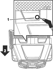
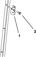
Installing the Grommet
Parts needed for this procedure:
| Grommet | 1 |
Routing the Wire Harness
Parts needed for this procedure:
| Wire harness | 1 |
| Cable tie | 2 |
For Electric Machines
Important: The Power Converter Kit is required to use the Windshield and Wiper Kit on a Workman GTX Electric utility vehicle. Contact your authorized Toro distributor for more information.
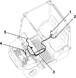
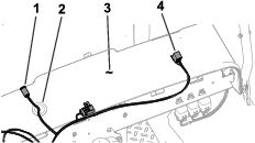
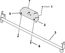
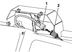
Use the following instructions and illustrations to route and connect the wire harness. Refer to Figure 2 for an overview of the wire harness position.
Note: The wire harness length allows for installation on a 4-passenger GTX machine. For 2-passenger GTX machines, coil the wire harness in the frame channel as shown in Figure 2.
-
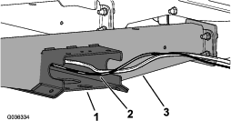
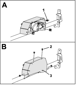
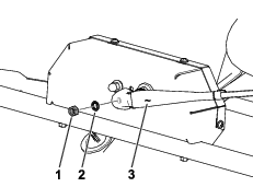
Route the wire harness along the floor-channel plate and through the opening in the frame channel (Figure 3).
-
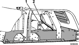
Route the wire harness through the opening in the top of the frame channel (Figure 4).
-
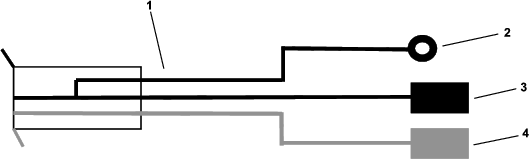
Pass the 6-socket connector of the wire harness through the grommet in the dashboard (Figure 5).
Use a cable tie to secure the wire harness to the machine.
Note: The 6-socket connector is installed in Installing the Wiper Motor.
-
Route the 8-socket connector of the wire harness toward the left side of the dash (Figure 5).
Use a cable tie to secure the wire harness to the machine.
Note: The 8-socket connector is installed in Installing the Switch.
-
Install the black ground wire to the ground wire on the Power Converter Kit wire harness (Figure 6).
Note: The black terminal ring is not used.
-
Install the red power wire to the power wire on the Power Converter Kit wire harness (Figure 6).
-
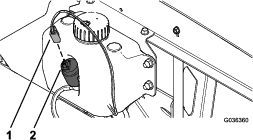
If you have the optional Washer Tank Kit (Toro Part No. 130-5615) installed, align the 2-socket connector of the wire harness to the 2-blade connector of the washer-fluid tank (Figure 7).
-
Push the wire-harness connector onto the tank connector until the connector fully seats (Figure 7).
For Gasoline Machines
Use the following instructions and illustrations to route and connect the wire harness. Refer to Figure 2 for an overview of the wire harness position.
Note: The wire harness length allows for installation on a 4-passenger GTX machine. For 2-passenger GTX machines, coil the wire harness in the frame channel as shown in Figure 2.
-
Route the wire harness along the floor-channel plate and through the opening in the frame channel (Figure 3).
-
Route the wire harness through the opening in the top of the frame channel (Figure 4).
-
Pass the 6-socket connector of the wire harness through the grommet in the dashboard (Figure 5).
Use a cable tie to secure the wire harness to the machine.
Note: The 6-socket connector is installed in Installing the Wiper Motor.
-
Route the 8-socket connector of the wire harness toward the left side of the dash (Figure 5).
Use a cable tie to secure the wire harness to the machine.
Note: The 8-socket connector is installed in Installing the Switch.
-
Install the black terminal ring to the ground block on the machine (Figure 8).
Note: The black ground wire is not used.
-
Install the red power wire into an empty slot on the machine fuse block (Figure 8).
Note: Install an additional fuse block if there are no remaining slots open in a fuse block.
-
Align the 2-socket connector of the wire harness to the 2-blade connector of the washer-fluid tank (Figure 7).
-
Push the wire-harness connector onto the tank connector until the connector fully seats (Figure 7).
Installing the Switch
Parts needed for this procedure:
| Rocker switch | 1 |
| Decal | 1 |
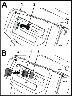
Refer to Figure 9 for this procedure.
-
Locate the plug that is adjacent to the hour meter on the dashboard
-
Remove the plug from the opening.
-
Pull the 8-socket connector of the wire harness through the opening in the dashboard.
-
Connect the 8-pin connector of the rocker switch into the 8-socket connector of the wire harness.
Ensure that the connectors are fully seated and the connector latches snap together securely.
-
Insert the switch into the opening in the dashboard until the switch snaps securely into the dashboard and apply the decal next to the switch.
Installing the Wiper Motor
Parts needed for this procedure:
| Wiper motor | 1 |
| Mount bracket | 1 |
| Mount bracket cover | 1 |
| Flange-head screw (1/4 x 1-1/2 inches) | 2 |
| Flange nut (1/4 inch) | 2 |
| Windshield support | 1 |
| Rubber pad | 3 |
-
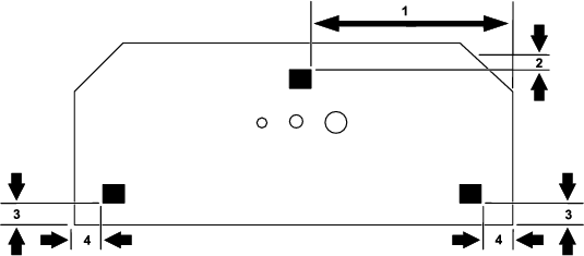
Apply the 3 rubber pads to the motor mount bracket using the measurements shown in Figure 10.
-
Use 2 flange-head screws (1/4 x 1-1/2 inches) and 2 flange nuts (1/4 inch) to secure the mount bracket to the windshield support (Figure 11).
-
Remove the hardware from the motor as shown in Figure 12.
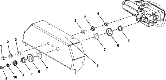
-
Use the hardware shown in Figure 12 to secure the motor to the mount bracket.
Note: Set aside the lock washer and wiper stud nut for use in Installing the Wiper
-
Torque the acorn nut to 7 to 8 N∙m (5 to 6 ft-lb) and torque the nut (M16) to 5 to 6 N∙m (3 to 4 ft-lb).
Installing the Windshield Support
Parts needed for this procedure:
| Flange-head screw (1/4 x 1-1/2 inches) | 4 |
| Flange nut (1/4 inch) | 4 |
| Windshield mount bracket | 2 |
| Hex-head screw (5/16 x 3/4 inch) | 2 |
| Phillips-head screw | 4 |
| Speed nut | 4 |
-
Secure the windshield support to the canopy tubes using 4 flange-head screws (1/4 x 1-1/2 inches) and 4 flange nuts (1/4 inch) as shown in Figure 13.
For installation on machines equipped with Model 07921 or 07922 canopies only:
You may need to loosen the canopy mounting hardware to install the windshield support.
-
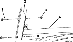
For installation on machines equipped with Model 07921 or 07922 canopies only:
In the top hole of the canopy tubes, install the windshield mounting brackets (Figure 14).
-
Connect the 6-socket connector of the kit wire harness to the 6-pin connector of the motor (Figure 15).
-
Use 4 Phillips-head screws and 4 speed nuts to secure the mount bracket cover to the mount bracket (Figure 16).
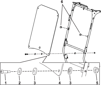
Installing the Windshield
Parts needed for this procedure:
| Windshield | 1 |
| Shoulder screw (5/16 x 1-1/4 inches) | 4 |
| Backup washer | 4 |
| Flange bushing | 8 |
| Flange nut (5/16 inch) | 4 |
| Bumper | 2 |
-
Remove the plastic protective coating from the windshield.
-
Secure the windshield to the windshield supports using 4 shoulder screws (5/16 x 1-1/4 inches), 4 backup washers, 8 flange bushings, 4 flange nuts (5/16 inch), and 2 bumpers (Figure 17).
Note: The windshield installation is the same for machines equipped with Model 07921 or 07922 canopies, with the exception of the bumpers, which are installed at the same height directly in the front of the canopy tubes. The bumper fit is tight; use grease, if necessary.
-
Thoroughly clean the windshield using an alcohol-based window cleaner to remove all the remaining residue from the plastic protective coating.
Connecting the Battery
For Gasoline GTX Vehicles
Connect the negative battery cable; refer to your machine Operator’s Manual.
For Electric GTX Vehicles
Connect the main negative battery cable (black) that connects the bank of batteries to the ground point of the machine; refer to your machine Operator’s Manual.
Installing the Wiper
Parts needed for this procedure:
| Wiper arm | 1 |
| Wiper blade | 1 |
-
Run the wiper motor for at least 1 cycle and allow it to return to its normal position.
-
Secure the wiper blade to the wiper arm.
-
Use the lock washer and wiper stud nut to install the arm to the motor (Figure 18).
-
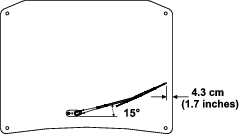
Position the arm using the measurements shown in Figure 19.
-
Torque the wiper stud nut to 23 to 29 N∙m (17 to 21 ft-lb).
Operation
Using the Wipers
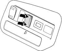
Press the rocker switch to turn the wipers to the ON or OFF position; refer to Figure 20.
Using the Wiper Fluid
Refer to the Windshield Wiper Kit Installation Instructions for wiper fluid operation.