| Maintenance Service Interval | Maintenance Procedure |
|---|---|
| Before each use or daily |
|
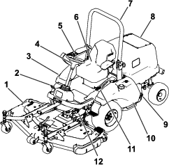
Introduction
This machine is a ride-on, multi-purpose machine intended to be used by professional, hired operators in commercial applications. It is primarily designed for maintaining grass on well-maintained lawns in parks, sports fields, and on commercial grounds. Using this product for purposes other than its intended use could prove dangerous to you and bystanders.
Read this information carefully to learn how to operate and maintain your product properly and to avoid injury and product damage. You are responsible for operating the product properly and safely.
Visit www.Toro.com for product safety and operation training materials, accessory information, help finding a dealer, or to register your product.
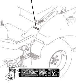
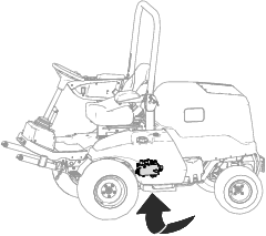
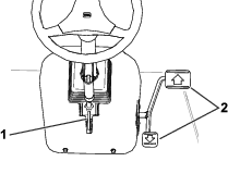
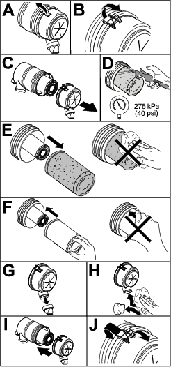
Whenever you need service, genuine Toro parts, or additional information, contact an Authorized Service Dealer or Toro Customer Service and have the model and serial numbers of your product ready. Figure 1 identifies the location of the model and serial numbers on the product. Write the numbers in the space provided.
Important: With your mobile device, you can scan the QR code on the serial number decal (if equipped) to access warranty, parts, and other product information.
This manual identifies potential hazards and has safety messages identified by the safety-alert symbol (Figure 2), which signals a hazard that may cause serious injury or death if you do not follow the recommended precautions.

This manual uses 2 words to highlight information. Important calls attention to special mechanical information and Note emphasizes general information worthy of special attention.
This product complies with all relevant European directives; for details, please see the separate product specific Declaration of Conformity (DOC) sheet.
It is a violation of California Public Resource Code Section 4442 or 4443 to use or operate the engine on any forest-covered, brush-covered, or grass-covered land unless the engine is equipped with a spark arrester, as defined in Section 4442, maintained in effective working order or the engine is constructed, equipped, and maintained for the prevention of fire.
The enclosed engine owner's manual is supplied for information regarding the US Environmental Protection Agency (EPA) and the California Emission Control Regulation of emission systems, maintenance, and warranty. Replacements may be ordered through the engine manufacturer.
Warning
CALIFORNIA
Proposition 65 Warning
Diesel engine exhaust and some of its constituents are known to the State of California to cause cancer, birth defects, and other reproductive harm.
Battery posts, terminals, and related accessories contain lead and lead compounds, chemicals known to the State of California to cause cancer and reproductive harm. Wash hands after handling.
Use of this product may cause exposure to chemicals known to the State of California to cause cancer, birth defects, or other reproductive harm.
Safety
This machine has been designed in accordance with ANSI B71.4-2017 and with EN ISO 5395 when you complete the setup procedures and install the CE Kit, per the Declaration of Conformity.
General Safety
This product is capable of amputating hands and feet and of throwing objects. Always follow all safety instructions to avoid serious personal injury.
-
Read and understand the contents of this Operator’s Manual before starting the engine.
-
Use your full attention while operating the machine. Do not engage in any activity that causes distractions; otherwise, injury or property damage may occur.
-
Do not operate the machine without all guards and other safety protective devices in place and functioning properly on the machine.
-
Keep your hands and feet away from rotating parts. Keep clear of the discharge opening.
-
Keep bystanders and children out of the operating area. Never allow children to operate the machine.
-
Shut off the engine, remove the key, and wait for all movement to stop before you leave the operator’s position. Allow the machine to cool before adjusting, servicing, cleaning, or storing it.
Improperly using or maintaining this machine can result in injury.
To reduce the potential for injury, comply with these safety instructions
and always pay attention to the safety-alert symbol  , which means Caution, Warning,
or Danger—personal safety instruction. Failure to comply with
these instructions may result in personal injury or death.
, which means Caution, Warning,
or Danger—personal safety instruction. Failure to comply with
these instructions may result in personal injury or death.
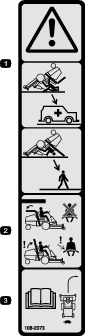
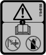
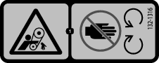
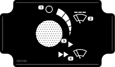
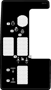
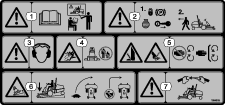
Safety and Instructional Decals
 |
Safety decals and instructions are easily visible to the operator and are located near any area of potential danger. Replace any decal that is damaged or missing. |


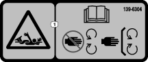

Decal 144-3952: Affix over Decal 139-6215 (as shown in the CE Kit Installation Instructions) for use in CE-compliant countries (Models 31900 and 31901 only).
Setup
Removing the Machine from the Shipping Container
Model 31902 Only
-
Remove the screws that hold down the rear wheel hubs to the pallet.
-
Cut the cable tie that holds the driveshaft to the rear tires.
-
Remove the rear wheels from the shipping skid.
-
Raise the roll bar; refer to Raising the Roll Bar.
-
Connect a hoist to the top, center area of the roll bar and raise the machine.
-
Remove the shipping skid from the bottom area of the machine.
-
Position 2 jack stands under the rear area of the machine shown in Raising the Rear of the Machine.
-
Lower the machine on the jack stands.
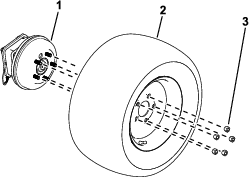
Installing the Rear Tires
Model 31902 Only
Parts needed for this procedure:
| Rear wheel | 2 |
| Lug nut | 8 |
-
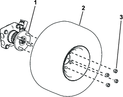
Use 4 lug nuts to secure the wheel to the wheel hub (Figure 3).
-
Torque the wheel lug nuts; refer to Torquing the Wheel-Lug Nuts.
Removing the Front Tires
Model 31902 Only
Note: You must perform this procedure to correctly install the lift arms.
-
Place jack stands under the front side-frame tubes to raise the front wheels; refer to Raising the Front of the Machine.
-
Loosen and remove the wheel lug nuts (Figure 11).
-
Removed the wheels from the wheel hubs (Figure 11).
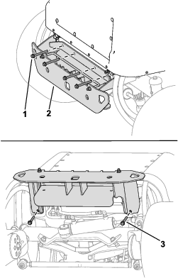
Installing the Lift-Arm Assembly
Model 31902 Only
Parts needed for this procedure:
| Right lift arm | 1 |
| Left lift arm | 1 |
| Large pin | 2 |
| Bolt (3/8 x 2-3/4 inches) | 2 |
| Nut (3/8 inch) | 6 |
| Small pin | 2 |
| Sensor bracket | 1 |
| Carriage bolt | 2 |
| Bolt (3/8 x 1-1/4 inches) | 2 |
| Grease fitting | 2 |
Note: Have an assistant help you to install the lift arms, as needed.
-
Remove the lift arms from the shipping skid.
-
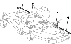
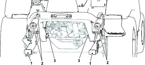
Use 2 large pins to install the lift arms to the machine frame (Figure 5).
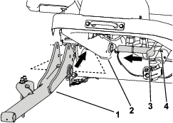
-
Install the grease fittings to the large pins (Figure 5).
-
Use 2 nuts (3/8 inch) and 2 bolts (3/8 x 2-3/4 inches) to secure the large pins to the frame (Figure 6).
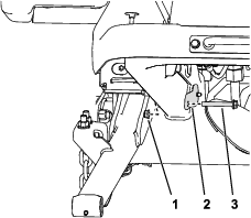
-
Use 2 carriage bolts and 2 nuts (3/8 inch) to secure the sensor bracket to the right lift arm (Figure 7).
Note: Ensure that the sensor bracket does not interfere with the sensor.
-
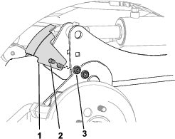
Perform the following steps to secure the hydraulic cylinders to the lift arms:
-
Place a drain pan under the hydraulic manifold (shown in Figure 8).
Note: A small amount of hydraulic fluid will need to be bled in order to manually retract the lift cylinders.
-
Loosen the hose swivel nut connected to port C1 of the hydraulic manifold (Figure 9).
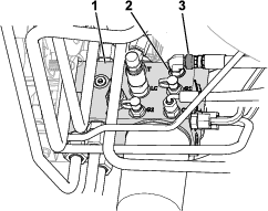
-
Use a drift punch to align the cylinder rod holes with the lift-arm holes (Figure 10).
Note: Fully raise the lift arm to help with the alignment.
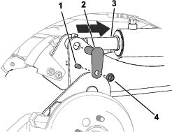
-
Use 2 bolts (3/8 x 1-1/4 inches), 2 nuts (3/8 inch), and 2 small pins to secure the lift arms to the cylinders (Figure 10).
-
Torque the hose swivel nut on port C1 (Figure 9) to 41 N∙m (30 ft-lb).
Note: You can use a backup wrench to prevent the hose from twisting.
-
-
Grease the attachment pin joints and lift-arm pin joints; refer to Greasing the Bearings and Bushings.
Installing the Front Tires
Model 31902 Only
-
Use the previously-removed lug nuts to secure the tires to the wheel hubs (Figure 11).
-
Torque the wheel lug nuts; refer to Torquing the Wheel-Lug Nuts
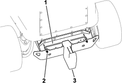
Installing the Tie-Down Bracket
Model 31902 Only
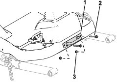
Parts needed for this procedure:
| Tie-down bracket | 1 |
| Bolt (3/8 x 3-1/4 inches) | 2 |
| Nut (3/8 inch) | 2 |
Use 2 bolts (3/8 x 3-1/4 inches) and 2 nuts (3/8 inch) to secure the tie-down bracket to the platform (Figure 12).
Installing the Seat
Model 31902 Only
Parts needed for this procedure:
| Seat Kit (ordered separately; refer to your authorized Toro distributor) | 1 |
Install the seat; refer to the Seat Kit Installation Instructions.
Installing the Steering Wheel
Model 31902 Only
Parts needed for this procedure:
| Steering wheel | 1 |
| Cover | 1 |
-
Remove the steering wheel from the shipping skid (Figure 13).
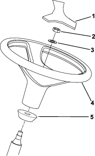
-
Remove the nylock nut and washer from the steering shaft.
Note: Ensure that the foam collar remains on the steering shaft (Figure 13).
-
Slide the steering wheel and washer onto the steering shaft (Figure 13).
-
Use the nylock nut to secure the steering wheel to the shaft. Tighten the nylock nut to 27 to 35 N∙m (20 to 26 ft-lb).
-
Mount the cover to the steering wheel (Figure 13).
Installing the Bumper
Model 31902 Only
Parts needed for this procedure:
| Bumper | 1 |
| Bolt (3/8 x 2-3/4 inches) | 2 |
| Bolt (3/8 x 3-1/4 inches) | 4 |
| Nut (3/8 inch) | 6 |
Connecting the Battery
Model 31902 Only
Connect the battery; refer to Connecting the Battery.
Installing the Attachment
Parts needed for this procedure:
| Optional attachment (ordered separately; refer to your authorized Toro distributor) | 1 |
| Socket-head screw (3/8 inch) | 2 |
| Washer (3/8 inch) | 2 |
| Flange locknut (3/8 inch) | 2 |
Important: When switching attachments, confirm with your authorized Toro distributor the correct number of rear weights for that specific attachment.
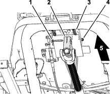
Install the front attachment (e.g., cutting unit, flail, plow blade, or blower); perform the following steps and refer to your attachment Operator’s Manual for additional installation instructions.
-
While supporting the driveshaft, remove the capscrew and locknut that secure the driveshaft yoke to the steering valve-mount bracket (Figure 15), and carefully lower the driveshaft.
Note: Discard the capscrew and locknut.
-
Ensure that the PTO shaft is aligned; refer to Aligning the PTO Driveshaft.
-
Have an assistant sit in the seat, turn the key to the ON position, and use the attachment lift switch to lower the lift arms while you push down on the lift arms.
-
Align the holes in the lift arm with the holes in the attachment arm as described in the attachment Installation Instructions.
-
Align the splines in the driveshaft yoke onto the splines of the attachment input shaft (Figure 16), and slide the yoke over the shaft.
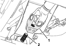
-
Assemble a socket-head capscrew (3/8 x 2-1/4 inches) through a washer (3/8 inch) and the hole in the driveshaft yoke (Figure 17), and secure the capscrew with a flange-locknut (3/8 inch).
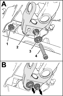
-
Assemble a socket-head capscrew (3/8 x 2-1/4 inches) through a washer (3/8 inch) and the hole in the driveshaft yoke from the opposite direction (Figure 17), and secure the capscrew with a flange-locknut (3/8 inch).
-
Incrementally torque the locknuts to 61 N∙m (45 ft-lb) in an alternating pattern.
Checking the Fluid Levels
Before you start the engine for the first time, perform the following fluid-level checks:
-
Check the engine-oil level; refer to Checking the Engine-Oil Level.
-
Check the coolant level; refer to Checking the Cooling System and Coolant Level.
-
Check the hydraulic-fluid level; refer to Checking the Hydraulic-Fluid Level.
Checking the Tire Pressure
Check the tire pressure; refer to Checking the Tire Air Pressure.
Important: Maintain pressure in all tires to ensure a good quality-of-cut and proper machine performance. Do not underinflate the tires.
Installing the CE Kit
Parts needed for this procedure:
| CE Kit (ordered separately; refer to your authorized Toro distributor) | 1 |
If you operate the machine in a country that complies to CE standards, install the CE Kit; refer to the kit Installation Instructions.
Adding Rear Weight
Parts needed for this procedure:
| Weight—19 kg (42 lb) [amount varies per your model] | |
| Weight—6 kg (15 lb) [amount varies per your model] |
Refer to the following table for the weight that is shipped with each machine:
| Model | Shipped Rear Weight |
| 31902 | 0 weights |
| 31903 | 5 weights (19 kg or 42 lb each) and 2 weights (6 kg or 15 lb each) |
Determining the Required Rear Weight
Ensure that your machine has the minimum amount of rear weight per your traction unit and attachment combination. For Model 31902, you can also add more rear weight for improved slope performance.
-
To determine the minimum number of weights required, refer to the Minimum Required Rear Weight table.
-
To achieve an improved slope performance, add the number of each weights as listed in the Required Rear Weight for Improved Slope Performance table.
To ensure proper ROPS performance, do not add more weight beyond the weight that is listed in this table.
Note: If you have an equipped CE Kit, refer to the kit Installation Instructions for the appropriate slope decal for your traction unit and attachment combination. Ensure that the correct amount of rear weight is added (i.e., weight to meet required slope standard or weight to meet improved slope performance).
| Traction Unit Model Number | Attachment Model Number(s) or Name | Number of Weights Required | ||
|---|---|---|---|---|
| 19 kg (42 lb) | 6 kg (15 lb) | Total | ||
 |  |
|||
| 31902 | 31970, 31971, 31974 | 0 | 0 | 0 |
| 31970, 31971, 31974 and Sunshade | 0 | 0 | 0 | |
| 31972, 31973, 31975 | 0 | 0 | 0 | |
| 31972, 31973, 31975 and Sunshade | 1 | 0 | 1 | |
| 02835 | 1 | 0 | 1 | |
| 02835 and Sunshade | 1 | 0 | 1 | |
| M-B Rotary Broom | 1 | 0 | 1 | |
| 31903 | 31970, 31971 | 5 | 2 | 7 |
| 31972, 31973 | ||||
| 02835 | ||||
| MSC23345 | ||||
| M-B Rotary Broom | ||||
| Erskine Snowthrower | ||||
| Traction Unit Model Number | Attachment Model Number(s) or Name | Number of Weights Required | ||
|---|---|---|---|---|
| 19 kg (42 lb) | 6 kg (15 lb) | Total | ||
| |
|||
| 31902 | 31970, 31971, 31974 | 4 | 0 | 4 |
| 31970 and Sunshade | 4 | 0 | 4 | |
| 31971, 31974 and Sunshade | 3 | 0 | 3 | |
| 31972, 31973, 31975 | 3 | 1 | 4 | |
| 31972, 31973, 31975 and Sunshade | 2 | 0 | 2 | |
| 02835 | 2 | 2 | 4 | |
| 02835 and Sunshade | 1 | 0 | 1 | |
If you need to add rear weight, contact your authorized Toro distributor for additional weights and refer to the following installation procedures:
Adding 19 kg (42 lb) Weights
-
Loosen the hardware that secures the weight-lock rod to the bumper.
-
Add the required amount of weights.
-
Tighten the weight-lock-rod hardware to secure the weight to the bumper.
Adding 6 kg (15 lb) Weights
-
Refer to your authorized Toro distributor to order the following parts:
Part Name Quantity Part Number Screw (3/8 x 3-1/2 inches) 2 116-4701 Washer 2 125-9676 Nut (3/8 inch) 2 104-8301 -
Use the hardware to secure the weights to the bumper (Figure 19).
Adjusting the Weight Transfer of the Attachment
Perform this procedure only if you are installing an attachment other than the standard rotary cutting units (e.g., snowthrower, blade, or flail).
You can change the hydraulic pressure used to transfer the weight of the attachment to the traction unit by adjusting the weight-transfer valve of the hydraulic manifold. For best performance, adjust the weight-transfer valve so that any bouncing motion of the attachment is minimal over uneven terrain, but also adjust the valve so that the attachment does not ride heavily over flat terrain or lower too quickly.
-
To improve the contour-tracking performance of the attachment as you operate the machine over uneven terrain, decrease the weight-transfer (hydraulic) pressure at the hydraulic manifold.
Note: If the attachment casters or the leading edge of the snowthrower float above the ground, the hydraulic pressure of the weight transfer valve is too high.
-
When you are cutting flat turf, when the cutting unit is scalping the grass, if the quality of cut is uneven from side to side, or the leading edge of a snowthrower is scraping too heavily, increase the weight-transfer pressure at the hydraulic manifold.
Note: Increasing weight-transfer pressure also transfers the weight from the attachment to the wheels of the traction unit, thereby improving the traction of the traction unit.
Adjust the weight-transfer pressure as follows:
-
Operate the machine for 10 minutes.
Note: This will warm the hydraulic fluid.
-
Park the machine on a level surface, lower the attachment, engage the parking brake, shut off the engine, and remove the key from the switch.
-
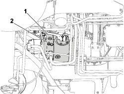
Locate the lift manifold from under the machine (Figure 20).
-
Connect a pressure gauge to the test port (labeled G1; refer to Figure 21).
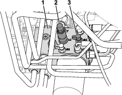
-
At the side of the lift manifold, remove the cap from the test port (labeled G1; refer to Figure 21).
-
Loosen the jam nut at the end of the weight-transfer spool (labeled LC; refer to Figure 21).
-
Start the engine, set the throttle to HIGH IDLE.
-
Use a hex-socket wrench to adjust the counterbalance valve of the weight-transfer spool until the gauge indicates the desired pressure; refer to the following table for the recommended pressure setting for the attachment.
-
Rotate the adjusting screw clockwise to increase the pressure.
-
Rotate the adjusting screw counterclockwise to decrease the pressure.
Attachment Weight-Transfer Pressure Rotary cutting unit 1,724 kPa (250 psi) Flail Mower (Model No. 02835) 1,379 kPa (200 psi) Snowthrower 1,724 kPa (250 psi) Snow Blade (Model No. 23350) 1,379 kPa (200 psi) Snow Broom 1,724 kPa (250 psi) -
-
Shut off the engine and remove the key.
-
Tighten the jam nut at the end of the weight-transfer spool, and torque the nut to 13 to 16 N∙m (10 to 12 ft-lb).
-
Install the cap on the test port.
-
Remove the pressure gauge from the test port.
Product Overview
Traction Pedal
Note: Adjust the seat position before you operate the machine. Refer to the seat kit Installation Instructions for seat-adjustment instructions.
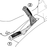
Use the traction pedal (Figure 23) to move the machine forward or rearward.
-
Move the machine forward: Use your toes to press the top of the pedal.
-
Move the machine rearward: Use your toes to press the bottom of the pedal.
Note: You can achieve steady operation by keeping your heel on the platform and pressing the pedal with your toes.
Ground speed is proportionate to how far the pedal is pressed. For maximum ground speed, you must fully press traction pedal while throttle is in the FAST position. Maximum speed forward is 24 km/h (15 mph).
To get maximum power under heavy load or when ascending a hill, have the throttle in the FAST position while pressing traction pedal slightly to keep the engine speed (rpm) high. If the engine speed begins to decrease rapidly, release the traction pedal slightly to allow the engine speed to increase.
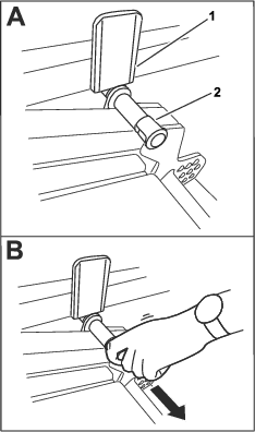
Tilt-Steering Lever
To tilt the steering wheel toward you, press the tilt-steering lever (Figure 23) down and pull the steering tower toward you. Release the lever when the steering tower is at a position that allows you to comfortably handle the steering wheel.
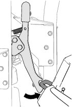
Parking Brake
Whenever you shut off the engine, engage the parking brake (Figure 16) to prevent the machine from accidentally moving.
-
Engage the parking brake: Pull the handle up to the ENGAGED position.
-
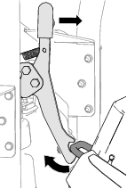
Disengage the parking brake: Use your thumb to push down the button on the top of handle and lower the handle down to the DISENGAGED position.
Note: If the handle is not completely lowered, the machine shuts off when you engage the traction pedal.
Console
Refer to the following sections for a description of the console controls (Figure 25).
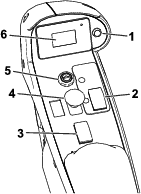
Attachment Lift Switch
The attachment lift switch raises the attachment to the highest position (i.e., the TRANSPORT position) and lowers the attachment to the lowest position (i.e., the OPERATING) position.
-
Raise the attachment: Press the rear of the switch.
-
Lower the attachment: Press the front of the switch.
Raise the attachment to the TRANSPORT position whenever you transport the machine between locations. Lower the attachment to the OPERATING position whenever you are not using the machine.
PTO Switch
-
Engage the PTO: Pull up on the switch.
-
Disengage the PTO: Push the switch down.
The only time you should engage the PTO is when the PTO attachment is in the OPERATING position (lowered to the ground with the driveshaft connected) and you are ready to begin operation.
Note: If you leave the operator’s seat while the PTO switch is in the ON position, the machine will automatically shut off the engine; refer to Resetting the PTO Function.
Key Switch
The key switch has 3 positions: OFF, ON/PREHEAT, and START.
Use the switch to start or shut off the engine [refer to Starting the Engine or Shutting Off the Engine] or to review the display-screen information [refer to Understanding the Display-Screen Information].
Throttle-Control Switch
Use the switch to adjust the engine speed.
-
Increase the engine speed: Press and release the front part of the switch to increase the speed by 100 rpm. Press and hold to increase the speed to the maximum amount.
-
Decrease the engine speed: Press the rear part of the switch to decrease the speed by 100 rpm. Press and hold to decrease the speed to the minimum amount (idle).
Display Screen
The display screen shows information about your machine, such as the operating status, various diagnostics, and other information.
Refer to Understanding the Display-Screen Information for more display-screen information.
Display Screen Button
Refer to Using the Display-Screen Button.
Cab Controls
Machines Equipped with a Cab
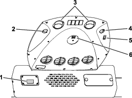
Windshield-Wiper Switch
Use the switch (Figure 26) to turn the windshield wipers on or off.
Fan-Control Knob
Rotate the fan-control knob (Figure 26) to regulate the speed of the fan.
Light Switch
Press the switch (Figure 26) to turn the dome light on or off.
Temperature-Control Knob
Rotate the temperature-control knob (Figure 26) to regulate the air temperature in the cab.
Note: Specifications and design are subject to change without notice.
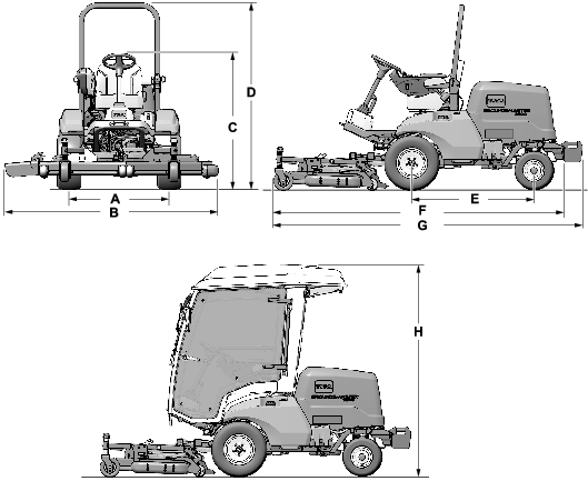
| Description | Figure 27 reference | Dimension or Weight | |
| Height with roll bar raised | D | 200 cm (79 inches) | |
| Height with roll bar lowered | C | 111 cm (44 inches) | |
| Height with cab | J | 226 cm (89 inches) | |
| Overall length (no rear weights equipped) [Model 31902] | With equipped attachment | F | Maximum of 312 cm (123 inches) |
| Traction unit only | H | Maximum of 253 cm (99.5 inches) | |
| Overall length (rear weights equipped) [Model 31903] | With equipped attachment | G | Maximum of 332 cm (131 inches) |
| Traction unit only | I | Maximum of 272 cm (107 inches) | |
| Overall width | B | Refer to Specifications. | |
| Wheel-base length | E | 132 cm (52 inches) | |
| Front-wheel tread width | A | 136 cm (53.5 inches) | |
| Rear-wheel tread width | 128 cm (50 inches) | ||
| Ground clearance | 21 cm (8-5/16 inches) | ||
| Net weight (Model 31902) | 855 kg (1,886 lb) | ||
| Net weight (Model 31903) | 1,128 kg (2,486 lb) | ||
Width Specifications
Refer to the following table for width measurements per your equipped cutting unit:
| Cutting Unit | Width |
| Model 31970 | 198 cm (78 inches) |
| Model 31971 | 168 cm (66 inches) |
| Model 31972 | 228 cm (90 inches) |
| Model 31973 | 198 cm (78 inches) |
| Model 31974 | 158 cm (62 inches) |
| Model 31975 | 188 cm (74 inches) |
| Model 02835 (Flail) | 218 cm (86 inches) |
Attachments/Accessories
A selection of Toro approved attachments and accessories is available for use with the machine to enhance and expand its capabilities. Contact your Authorized Service Dealer or authorized Toro distributor or go to www.Toro.com for a list of all approved attachments and accessories.
To ensure optimum performance, use only genuine Toro replacement parts and accessories. Replacement parts and accessories made by other manufacturers could be dangerous, and such use could void the product warranty
Operation
Before Operation
Before Operation Safety
General Safety
-
Never allow children or untrained people to operate or service the machine. Local regulations may restrict the age of the operator. The owner is responsible for training all operators and mechanics.
-
Become familiar with the safe operation of the equipment, operator controls, and safety signs.
-
Shut off the engine, remove the key, and wait for all movement to stop before you leave the operator’s position. Allow the machine to cool before adjusting, servicing, cleaning, or storing it.
-
Know how to stop the machine and shut off the engine quickly.
-
Check that operator-presence controls, safety switches, and guards are attached and functioning properly. Do not operate the machine unless they are functioning properly.
-
Before mowing, always inspect the machine to ensure that the blades, blade bolts, and cutting assemblies are in good working condition. Replace worn or damaged blades and bolts in sets to preserve balance.
-
Inspect the area where you will use the machine and remove all objects that the machine could throw.
Fuel Safety
-
Use extreme care in handling fuel. It is flammable and its vapors are explosive.
-
Extinguish all cigarettes, cigars, pipes, and other sources of ignition.
-
Use only an approved fuel container.
-
Do not remove the fuel cap or fill the fuel tank while the engine is running or hot.
-
Do not add or drain fuel in an enclosed space.
-
Do not store the machine or fuel container where there is an open flame, spark, or pilot light, such as on a water heater or other appliance.
-
If you spill fuel, do not attempt to start the engine; avoid creating any source of ignition until the fuel vapors have dissipated.
Checking the Machine Daily
Check the following machine systems each day before operating the machine:
-
Air-cleaner indicator; refer to Servicing the Air Cleaner
-
Engine oil; refer to Checking the Engine-Oil Level
-
Coolant system; refer to Checking the Cooling System and Coolant Level
-
Hood screen and radiator; refer to Checking the Cooling Fins
-
Hydraulic system; refer to Checking the Hydraulic-Fluid Level
-
PTO-shaft grease points; refer to Greasing the Bearings and Bushings
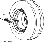
Checking the Tire Air Pressure
Tire air pressure specification: 138 kPa (20 psi)
Danger
Low tire pressure decreases machine side-hill stability. This could cause a rollover, which may result in personal injury or death.
Do not underinflate the tires.
Check the air pressure in the front and rear tires. Add or remove air as needed to set the air pressure in the tires to the tire air pressure specification.
Important: Maintain pressure in all tires to ensure a good quality of cut and proper machine performance.Check the air pressure in all the tires before operating the machine.
Adding Fuel
Fuel Specification
Important: Use only ultra-low sulphur diesel fuel.Failure to observe the following cautions may damage the engine.
-
Never use kerosene or gasoline instead of diesel fuel.
-
Never mix kerosene or used engine oil with the diesel fuel.
-
Never keep fuel in containers with zinc plating on the inside.
-
Do not use fuel additives.
-
Use only clean, fresh diesel fuel or biodiesel fuels.
-
Purchase fuel in quantities that you can use within 180 days to ensure fuel freshness.
Petroleum Diesel
Cetane rating: 40 or higher
Sulfur content: Ultra-low sulfur (<15 ppm)
Use summer-grade diesel fuel (No. 2-D) at temperatures above -7°C (20°F) and winter-grade fuel (No. 1-D or No. 1-D/2-D blend) below that temperature.
Note: Use of winter-grade fuel at lower temperatures provides lower flash point and cold flow characteristics which eases starting and reduces fuel filter plugging.Using summer-grade fuel above -7°C (20°F) contributes toward longer fuel pump life and increased power compared to winter-grade fuel.
Biodiesel
This machine can also use a biodiesel blended fuel of up to B20 (20% biodiesel, 80% petroleum diesel).
Sulfur content: Ultra-low sulfur (<15 ppm)
Biodiesel fuel specification: ASTM D6751 or EN14214
Blended fuel specification: ASTM D975, EN590, or JIS K2204
Important: The petroleum diesel portion must be ultra-low sulfur.
Observe the following precautions:
-
Biodiesel blends may damage painted surfaces.
-
Use B5 (biodiesel content of 5%) or lesser blends in cold weather.
-
Monitor seals, hoses, gaskets in contact with fuel as they may degrade over time.
-
Fuel filter plugging may occur for period after converting to biodiesel blends.
-
Contact your authorized Toro distributor if you wish for more information on biodiesel.
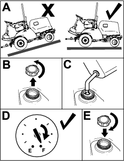
Filling the Fuel Tank
Fuel tank capacity: 45 L (12 US gallons)
Note: If possible, fill the fuel tank after each use; this minimizes condensation buildup inside the fuel tank.
-
Park the machine on a level surface (Figure 29), engage the parking brake, shut off the engine, and remove the key
-
Unscrew the cap from the fuel tank.
-
Fill the fuel tank with the specified fuel until the fuel-gauge dial indicates that the tank is full.
-
Screw the cap onto the fuel tank.
Checking the Safety-Interlock System
| Maintenance Service Interval | Maintenance Procedure |
|---|---|
| Before each use or daily |
|
The purpose of the safety-interlock system is to prevent the engine from cranking or starting unless the traction pedal is in neutral and the PTO switch is in the OFF position. In addition, the engine should stop when the following occurs:
-
The PTO switch is set to the ON position and you are not in the seat.
-
The traction pedal is pressed but you are not in the seat.
-
The traction pedal is pressed and the parking brake is engaged.
Caution
If the safety-interlock switches are disconnected or damaged, the machine could operate unexpectedly, causing personal injury.
-
Do not tamper with the interlock switches.
-
Check the operation of the interlock switches daily and replace any damaged switches before operating the machine.
-
Move the PTO switch to OFF position and remove your foot from traction pedal.
-
Rotate the key switch to the START position. If the engine cranks, proceed to step 3.
Note: If engine does not crank, there may be a malfunction in the safety-interlock system.
-
With the engine running, rise from the seat and set the PTO switch to the ON position . The engine should shut off within 2 seconds. If the engine shuts off, proceed to step 4.
Important: If engine does not shut off, there is a malfunction in the safety-interlock system. Refer to your authorized Toro distributor.
-
With the engine running and the PTO switch set to the OFF position, raise off the seat and press the traction pedal. The engine should shut off within 2 seconds. If engine shuts off, proceed to step 5.
Important: If engine does not shut off, there is a malfunction in the safety-interlock system. Refer to your authorized Toro distributor.
-
Engage the parking brake. With the engine running and the PTO switch set to the ON position, press the traction pedal. The engine should shut off within 2 seconds. If engine shuts off, the switch is operating correctly; the interlock system is ready for machine operation.
Important: If engine does not shut off, there is a malfunction in the safety-interlock system. Refer to your authorized Toro distributor.
Adjusting the Roll Bar
Warning
A rollover can cause injury or death.
-
Keep the roll bar in the raised locked position.
-
Use the seat belt.
Warning
There is no rollover protection when the roll bar is lowered.
-
Do not operate the machine on uneven ground or on a hill side with a lowered roll bar.
-
Lower the roll bar only when absolutely necessary.
-
Do not wear the seat belt when the roll bar is lowered.
-
Drive slowly and carefully.
-
Raise the roll bar as soon as clearance permits.
-
Check carefully for overhead clearances (e.g., branches, doorways, or electrical wires) before driving under any objects and do not contact them.
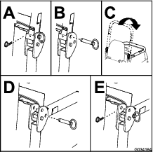
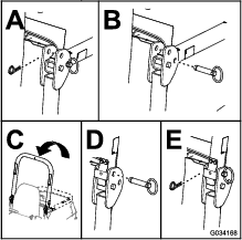
Lowering the Roll Bar
Important: Lower the roll bar only when absolutely necessary.
-
Park the machine on a level surface, engage the parking brake, lower the cutting unit, shut off the engine, and remove the key.
-
Remove the cotter pins and pins from the roll bar (Figure 30).
-
Lower the roll bar and secure it in place with the pins and cotter pins (Figure 30).
Raising the Roll Bar
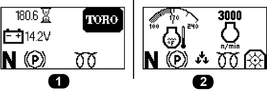
Understanding the Display-Screen Information
The display screen shows information about your machine, such as the operating status, various diagnostics, and other information about the machine. There are two main-information screens (Figure 32) and a main menu screen.
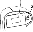
Using the Display-Screen Button
Use the display-screen button (shown in Figure 33) to toggle between the 2 main-information screens and to access the main menu.
-
To access the main menu: Hold down the display-screen button until the menu items appear on the screen.
-
To select a menu item: Quickly press the display-screen button twice.
You can also perform this action to toggle an option (e.g., toggling between English or metric units in the SETTINGS screen).
-
To return to the previous screen (e.g., returning to the MAIN MENU screen from the SETTINGS screen, or returning to the main-information screens from the MAIN MENU screen): Hold down the display-screen button until the previous screen appears.
-
To scroll down to the next menu item: Press the display-screen button once.
Understanding the Menu Items
| Menu Item | Description |
| FAULTS | Contains a list of the recent machine faults. Refer to the Service Manual or your authorized Toro distributor for more information on the FAULTS menu. |
| SERVICE | Contains information on the machine such as hours of use, counts and DPF regeneration. Refer to the Service table. |
| DIAGNOSTICS | Lists various states and data that the machine currently has. You can use this information to troubleshoot certain issues, as it quickly tells you which machine controls are on/off and lists control levels (e.g., sensor values). |
| SETTINGS | Allows you to customize and modify configuration variables on the InfoCenter display. Refer to the Settings table. |
| ABOUT | Lists the model number, serial number, and software version of your machine. Refer to the About table. |
| Menu Item | Description |
| HOURS | Lists the total number of hours that the key, engine, and PTO have been on. |
| COUNTS | Lists the number of engine and PTO starts. |
| DPF REGENERATION | Allows you to control DPF settings; refer to Understanding the Diesel-Particulate Filter and Regeneration. |
| Menu Item | Description |
| UNITS | Controls the units used on the display screen. The menu choices are English or metric. |
| LANGUAGE | Controls the language used on the display screen. |
| BACKLIGHT | Controls the brightness of the display screen. |
| CONTRAST | Controls the contrast of the display screen. |
| PROTECTED MENUS | Allows a person authorized by your company with the PIN code to access protected menus (i.e., the slope sensor setting and the ability to clear the fault log). |
| PROTECT SETTINGS | When disabled, you can access protected settings without entering the PIN code. |
| PTO SOFTSTART: | Enables or disables the PTO Softstart feature. This feature is enabled by default. |
| SLOPE SENSOR INSTALLED | Shows whether or not a slope sensor is installed. If a slope sensor is removed from the machine, this setting can be disabled to clear the slope-sensor communication fault. |
| Menu Item | Description |
| DECK | Indicates if the cutting unit inputs/outputs are active. |
| PTO | Indicates if the PTO is active. |
| ENGINE | Indicates if the engine inputs/outputs are active. |
| Menu Item | Description |
| MODEL | Lists the model number of the machine. |
| SN | Lists the serial number of the machine. |
| S/W REV | Lists the software revision of the master controller. |
Understanding the Display-Screen Icons
Refer to the following table for a description of each display-screen icon:
 | Engine speed |
 | Engine fault |
 | Hour meter |
 | Air intake heater is active |
 | Operator must sit in seat |
 | Parking brake is engaged |
 | Neutral |
 | PTO is engaged |
 | PTO is disabled |
 | Indicates when the cutting units are being lowered |
 | Indicates when the cutting units are being raised |
 | PIN passcode |
 | Battery |
 | Coolant temperature |
 | Reset-standby regeneration request |
| Parked or recovery regeneration request | |
 | A parked or recovery-standby regeneration is processing. |
 | High exhaust temperature |
 | NOx control diagnosis malfunction; drive the machine back to the shop and contact your authorized Toro distributor. |
Accessing the Protected Menus
Note: The factory default PIN code for you machine is “1234”.
If you changed the PIN code and forgot the code, contact your authorized Toro distributor for assistance.
-
Select the SETTINGS option.
-
Select the PROTECTED MENUS option.
-
To enter the PIN code, press the display-screen button until the appropriate digit appears, then quickly press the display-screen button twice to move to the next digit.
-
After all four digits are entered, press the display button once to submit the PIN code.
If the PIN code has been entered correctly, the PIN icon will appear at the top right of all menu screens.
During Operation
During Operation Safety
General Safety
-
The owner/operator can prevent and is responsible for accidents that may cause personal injury or property damage.
-
Wear appropriate clothing, including eye protection; long pants; substantial, slip-resistant footwear; and hearing protection. Tie back long hair and do not wear loose clothing or loose jewelry.
-
Do not operate the machine while ill, tired, or under the influence of alcohol or drugs.
-
Use your full attention while operating the machine. Do not engage in any activity that causes distractions; otherwise, injury or property damage may occur.
-
Before you start the engine, ensure that all drives are in neutral, the parking brake is engaged, and you are in the operating position.
-
Do not carry passengers on the machine and keep bystanders and children out of the operating area.
-
Operate the machine only in good visibility to avoid holes or hidden hazards.
-
Avoid mowing on wet grass. Reduced traction could cause the machine to slide.
-
Keep your hands and feet away from rotating parts. Keep clear of the discharge opening.
-
Look behind and down before backing up to be sure of a clear path.
-
Use care when approaching blind corners, shrubs, trees, or other objects that may obscure your vision.
-
Stop the blades whenever you are not mowing.
-
Stop the machine, remove the key, and wait for all moving parts to stop before inspecting the attachment after striking an object or if there is an abnormal vibration in the machine. Make all necessary repairs before resuming operation.
-
Slow down and use caution when making turns and crossing roads and sidewalks with the machine. Always yield the right-of-way.
-
Disengage the drive to the cutting unit, shut off the engine, remove the key, and wait for all movement to stop before adjusting the height of cut (unless you can adjust it from the operating position).
-
Operate the engine only in well-ventilated areas. Exhaust gases contain carbon monoxide, which is lethal if inhaled.
-
Never leave a running machine unattended.
-
Before you leave the operator’s position, do the following:
-
Park the machine on a level surface.
-
Disengage the power takeoff and lower the attachments.
-
Engage the parking brake.
-
Shut off the engine and remove the key.
-
Wait for all movement to stop.
-
-
Operate the machine only in good visibility. Do not operate the machine when there is the risk of lightning.
-
Do not use the machine as a towing vehicle.
-
Use accessories, attachments, and replacement parts approved by Toro only.
Rollover Protection System (ROPS) Safety
-
The ROPS is an integral and effective safety device.
-
Do not remove any of the ROPS components from the machine.
-
Ensure that the seat belt is attached to the machine.
-
Pull the belt strap over your lap and connect the belt to the buckle on the other side of the seat.
-
To disconnect the seat belt, hold the belt, press the buckle button to release the belt, and guide the belt into the auto-retract opening. Ensure that you can release the belt quickly in an emergency.
-
Check carefully for overhead obstructions and do not contact them.
-
Keep the ROPS in safe operating condition by thoroughly inspecting it periodically for damage and keeping all the mounting fasteners tight.
-
Replace damaged ROPS components. Do not repair or alter them.
Additional ROPS Safety for Machines with a Cab or a Fixed Roll Bar
-
A cab installed by Toro is a roll bar.
-
Always wear your seat belt.
Additional ROPS Safety for Machines with a Foldable Roll Bar
-
Keep a folding roll bar in the raised and locked position, and wear your seat belt when operating the machine with the roll bar in the raised position.
-
Lower a folding roll bar temporarily only when necessary. Do not wear the seat belt when the roll bar is folded down.
-
Be aware that there is no rollover protection when a folded roll bar is in the down position.
-
Check the area that you will be mowing and never fold down a folding roll bar in areas where there are slopes, drop-offs, or water.
Slope Safety
-
Slopes are a major factor related to loss of control and rollover accidents, which can result in severe injury or death. You are responsible for safe slope operation. Operating the machine on any slope requires extra caution.
-
Evaluate the site conditions to determine if the slope is safe for machine operation, including surveying the site. Always use common sense and good judgment when performing this survey.
-
Review the slope instructions listed below for operating the machine on slopes and to determine whether you can operate the machine in the conditions on that day and at that site. Changes in the terrain can result in a change in slope operation for the machine.
-
Avoid starting, stopping, or turning the machine on slopes. Avoid making sudden changes in speed or direction. Make turns slowly and gradually.
-
Do not operate a machine under any conditions where traction, steering, or stability is in question.
-
Remove or mark obstructions such as ditches, holes, ruts, bumps, rocks, or other hidden hazards. Tall grass can hide obstructions. Uneven terrain could overturn the machine.
-
Be aware that operating the machine on wet grass, across slopes, or downhill may cause the machine to lose traction. Loss of traction to the drive wheels may result in sliding and a loss of braking and steering.
-
Use extreme caution when operating the machine near drop-offs, ditches, embankments, water hazards, or other hazards. The machine could suddenly roll over if a wheel goes over the edge or the edge caves in. Establish a safety area between the machine and any hazard.
-
Identify hazards at the base of the slope. If there are hazards, mow the slope with a pedestrian-controlled machine.
-
If possible, keep the cutting unit(s) lowered to the ground while operating on slopes. Raising the cutting unit(s) while operating on slopes can cause the machine to become unstable.
-
Use extreme caution with grass-collection systems or other attachments. These can change the stability of the machine and cause a loss of control.
Understanding the Diesel-Particulate Filter and Regeneration
The diesel-particulate filter (DPF) removes soot from the engine exhaust.
The DPF regeneration process uses heat from the engine exhaust that is increased by the catalyst to reduce accumulated soot into ash.
To keep the DPF clean, remember the following:
-
Run the engine at full engine speed when possible to promote DPF self-cleaning.
-
Use the correct engine oil.
-
Minimize the amount of time that you idle the engine.
-
Use only ultra low sulfur diesel fuel.
Operate and maintain your machine with the function of the DPF in mind. Engine under load generally produces adequate exhaust temperature for DPF regeneration.
Important: Minimize the amount of time that you idle the engine or operate the engine at low-engine speed to help reduce the accumulation of soot in the DPF.
Caution
The exhaust temperature is hot (approximately 600°C (1,112°F) during DPF regeneration. Hot exhaust gas can harm you or other people.
-
Do not operate the engine in an enclosed area.
-
Ensure that there are no flammable materials around the exhaust system.
-
Ensure that the hot exhaust gas does not contact surfaces that may be damaged by heat.
-
Do not touch a hot exhaust system component.
-
Do not stand near or around the exhaust pipe of the machine.
Understanding the Regeneration Icons
| Icon | Icon Definition |
 | • Parked or recovery regeneration icon-regeneration is requested. |
| • Perform the regeneration immediately. | |
 | • Notes that a regeneration is acknowledged |
 | • Notes that a regeneration is in progress and the exhaust temperature is elevated |
 | • Inhibit regeneration is selected |
| • NOx control system malfunction; the machine requires service. |
Types of Diesel Particulate Filter Regeneration
| Regeneration Type | Conditions that cause DPF regeneration | DPF description of operation |
|---|---|---|
| Reset | Occurs every 100 hours | • When the high exhaust-temperature icon  is displayed in the InfoCenter,
a regeneration is in progress. is displayed in the InfoCenter,
a regeneration is in progress. |
| Also occurs if normal engine operation surpasses the allowed soot accumulation amount within the filter | ||
| • During reset regeneration, the engine computer maintains an elevated engine speed to ensure filter regeneration. | ||
| • Avoid shutting off the engine while the reset regeneration is processing. |
| Regeneration Type | Conditions that cause DPF regeneration | DPF description of operation |
|---|---|---|
| Parked | Occurs because the computer determines that the automatic DPF cleaning has not been sufficient. | • When the reset-standby/parked
or recovery regeneration icon  or a regeneration is requested. or a regeneration is requested. |
| Also occurs because you initiate a parked regeneration | ||
| May occur because the inhibit regen has been initiated and has disabled the automatic DPF cleaning from occuring | • Perform the parked regeneration as soon as possible to avoid needing a recovery regeneration. | |
| May result from using the incorrect fuel or engine oil | • A parked regeneration requires 30 to 60 minutes to complete. | |
| • You must have at least a 1/2 tank of fuel in the tank. | ||
| • You must park the machine to perform a parked regeneration. | ||
| Recovery | Occurs because the request for parked recovery has been ignored, allowing the DPF to be critically plugged | • When the reset-standby/parked or recovery
regeneration icon a recovery regeneration is requested. |
| • A recovery regeneration requires up to 3 hours to complete. | ||
| • You must have at least a 1/2 tank of fuel in the machine. | ||
| • You must park the machine to perform a recovery regeneration. |
Using the DPF Regeneration Menus
Accessing the DPF Regeneration Menus
-
Navigate to the SERVICE menu from the main menu.
-
Select the DPF REGENERATION option.
Time Since Last Regeneration
-
Access the DPF Regeneration menu, and scroll to the LAST REGEN option.
-
Use the LAST REGEN field to determine how many hours you have run the engine since the last reset, parked, or recovery regeneration.
Setting the Inhibit Regen
Reset Regeneration Only
A reset regeneration produces elevated engine exhaust. If you are operating the machine around trees, brush, tall grass, or other temperature-sensitive plants or materials, you can use the INHIBIT REGEN setting to prevent the engine computer from performing a reset regeneration.
Note: The INHIBIT REGEN option is always used when maintenance is being performed on the machine in an enclosed area.
Note: If you set the InfoCenter to inhibit regeneration, the InfoCenter displays an advisory every 15 minutes while the engine requests a reset regeneration.
Important: When you shut off the engine and start it again, the inhibit regen setting defaults to OFF.
-
Access the DPF Regeneration menu, and scroll down to the INHIBIT REGEN option.
-
Select the Inhibit REGEN entry.
-
Change the inhibit regeneration setting from Off to On.
Preparing to Perform a Parked or Recovery Regeneration
-
Ensure that the machine has fuel in the tank for the type of regeneration you are performing:
-
Parked Regeneration: Ensure that you have 1/4 tank of fuel before performing the parked regeneration.
-
Recovery Regeneration: Ensure that you have 1/2 tank of fuel before performing the recovery regeneration.
-
-
Move the machine outside to an area away from combustible materials or items that may be damaged by heat.
-
Park the machine on a level surface.
-
Disengage the PTO, and lower any attachments (if equipped).
-
Engage the parking brake.
-
Set the throttle to the low IDLE position.
-
Ensure that the air-conditioning is off (machines equipped with a cab only).
Performing a Parked or Recovery Regeneration
When a parked regeneration is requested by the engine computer, follow the messages on the InfoCenter.
Important: The computer of the machine cancels DPF regeneration if you increase the engine speed from low idle or release the parking brake.
-
Access the DPF Regeneration menu, and scroll down to the PARKED REGEN option or the RECOVERY REGEN option.
-
Select the PARKED REGEN entry or the RECOVERY REGEN entry.
-
At the VERIFY FUEL LEVEL screen, verify that you have 1/4 tank of fuel if you are performing the parked regeneration or 1/2 tank of fuel if you are performing the recovery regeneration, and press the display-screen button icon to continue.
-
On the Parked Regen menu or Recovery Regen menu, press the display-screen button to start the regeneration.
-
At the DPF checklist screen, verify that the parking brake is engaged, that the engine speed is set to low idle, and press the display-screen button icon to continue.
-
At the INITIATE DPF REGEN screen, select the display-screen button to continue.
-
The InfoCenter displays the INITIATING DPF REGEN message.
Note: If needed, hold the display-screen button to cancel the regeneration process.
-
The InfoCenter displays the time to complete message.
-
The InfoCenter displays the home screen and the regeneration acknowledge icon appears
.Note: While the DPF regeneration runs, the InfoCenter displays the high exhaust-temperature icon
. -
When the engine computer completes a parked or recovery regeneration, the InfoCenter displays an advisory. Press any button to exit to the home screen.
Note: If the regeneration fails to complete, follow the advisory and press any button to exit to the home screen.
Canceling a Parked or Recovery Regeneration
Use the PARKED REGEN CANCEL or RECOVERY REGEN CANCEL setting to cancel a running parked or recovery regeneration process.
-
Access the DPF Regeneration menu, scroll down to the PARKED REGEN option or the RECOVERY REGEN option.
-
Press the next screen to cancel a Parked Regen or cancel a Recovery Regen.
Starting the Engine
-
Sit on the operator’s seat and fasten the seat belt.
-
Ensure that the parking brake is engaged and the PTO is disengaged.
-
Preheat the engine by rotating the key switch to the ON/PREHEAT position.
Note: An automatic timer controls the preheat for 6 seconds.
-
Rotate the key to the START position, crank the engine for no longer than 15 seconds, and allow the key to return to the ON/PREHEAT position.
Note: If additional preheating is required, turn the key to the OFF position, then to the ON/PREHEAT position. Repeat this process as needed.
-
Move the throttle to idle speed or partial throttle and run the engine until it warms up.
Resetting the PTO Function
Note: If you leave the operator’s seat while the PTO switch is in the ON position, the machine will automatically shut off the engine.
Perform the following to reset the PTO function:
-
Push down the PTO switch.
-
Start the engine; refer to Starting the Engine.
-
Pull up the PTO switch.
Shutting Off the Engine
-
Use the throttle control to lower the engine speed.
-
Move the PTO switch to the OFF position.
-
Rotate the key switch to the OFF position and remove the key from the switch.
After Operation
After Operation Safety
General Safety
-
Shut off the engine, remove the key, and wait for all movement to stop before you leave the operator’s position. Allow the machine to cool before adjusting, servicing, cleaning, or storing it.
-
Clean grass and debris from the cutting units, mufflers, and engine compartment to help prevent fires. Clean up oil or fuel spills.
-
If the cutting units are in the transport position, use the positive mechanical lock (if available) before you leave the machine unattended.
-
Allow the engine to cool before storing the machine in any enclosure.
-
Remove the key and shut off the fuel (if equipped) before storing or hauling the machine.
-
Never store the machine or fuel container where there is an open flame, spark, or pilot light, such as on a water heater or on other appliances.
-
Maintain and clean the seat belt(s) as necessary
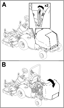
Servicing the Cutting Unit
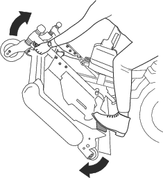
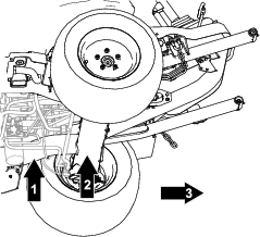
You can rotate the cutting unit from the TRANSPORT position (A in Figure 34) to the SERVICE position (B in Figure 34). Use the SERVICE position to maintain the cutting unit blades or clean underneath the cutting unit; refer to your cutting unit Operator’s Manual.

Rotating the Cutting Unit to the
Perform this procedure to rotate the cutting unit from the TRANSPORT position to the SERVICE position.
Warning
If you leave the key in the switch, someone could accidently start the engine and seriously injure you or other bystanders.
Remove the key from the switch and do not start the engine with the cutting unit in the SERVICE position.
-
Park the machine a level surface.
-
Press the lift switch to raise the cutting unit to the TRANSPORT position.
-
Engage the parking brake, shut off the engine, and remove the key.
-
Remove the pins from the height-of-cut plates (Figure 35).
-
Rotate the cutting unit (Figure 36) so that the latch engages with the tie-down bracket (Figure 37).
Warning
The cutting unit is heavy.
Use assistance when you lift the cutting unit.
Rotating the Cutting Unit to the
Perform this procedure to rotate the cutting unit from the SERVICE position to the TRANSPORT position.
-
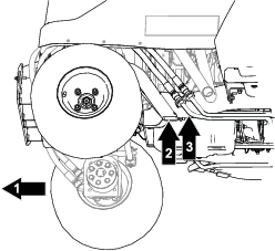
Release the cutting-unit latch from the tie-down bracket (Figure 38) by slightly rotating the cutting unit slightly forward (refer to Figure 36) and pulling the latch handle forward.
-
Slowly rotate the cutting unit down until the pin contacts the lift-arm plate (A in Figure 39).
-
Use your foot to press down on the cutting unit, then pull out on the pin (B in Figure 39) to let the cutting unit settle into the TRANSPORT position.
-
Insert the height-of-cut pins through the height-of-cut plates and chains.
Towing the Machine
If it becomes necessary to tow or push the machine, the traction pump must be set to bypass hydraulic fluid. Move the machine at a speed below 4.8 kph (3 mph), and for a very short distance.
Important: If towing limits are exceeded, severe damage to the hydraulic pump may occur.If the machine needs to be moved more than a short distance, the machine should be transported on a trailer.
-
Access the bypass valve from under the machine.
-
Use an 18 mm (11/16 inch) box-end wrench to loosen the bypass valve, then open the valve 3 revolutions maximum.
Important: Do not start or run the engine when the valve is set to the bypass position.
-
After towing and before starting the engine, tighten the bypass valve to 20 N·m (15 ft-lb).
Hauling the Machine
-
Use care when loading or unloading the machine into a trailer or a truck.
-
Use full-width ramps for loading the machine into a trailer or a truck.
-
Tie the machine down securely.
-
Remove the key before storing or hauling the machine.
Maintenance
Note: Determine the left and right sides of the machine from the normal operating position.
Note: Download a free copy of the electrical or hydraulic schematic by visiting www.Toro.com and searching for your machine from the Manuals link on the home page.
Maintenance Safety
-
Before you leave the operator’s position, do the following:
-
Park the machine on a level surface.
-
Disengage the power takeoff and lower the attachments.
-
Engage the parking brake.
-
Shut off the engine and remove the key.
-
Wait for all movement to stop.
-
-
If you leave the key in the switch, someone could accidently start the engine and seriously injure you or other bystanders. Remove the key from the switch before you perform any maintenance.
-
Allow machine components to cool before performing maintenance.
-
If the cutting units are in the transport position, use the positive mechanical lock (if equipped) before you leave the machine unattended.
-
If possible, do not perform maintenance while the engine is running. Keep away from moving parts.
-
Support the machine with jack stands whenever you work under the machine.
-
Carefully release pressure from components with stored energy.
-
Keep all parts of the machine in good working condition and all hardware tightened, especially blade-attachment hardware.
-
Replace all worn or damaged decals.
-
To ensure safe, optimal performance of the machine, use only genuine Toro replacement parts. Replacement parts made by other manufacturers could be dangerous, and such use could void the product warranty.
Recommended Maintenance Schedule(s)
| Maintenance Service Interval | Maintenance Procedure |
|---|---|
| After the first hour |
|
| After the first 10 hours |
|
| After the first 50 hours |
|
| After the first 1000 hours |
|
| Before each use or daily |
|
| Every 50 hours |
|
| Every 100 hours |
|
| Every 200 hours |
|
| Every 250 hours |
|
| Every 400 hours |
|
| Every 500 hours |
|
| Every 800 hours |
|
| Every 1,000 hours |
|
| Every 1,500 hours |
|
| Every 2,000 hours |
|
| Monthly |
|
| Yearly |
|
| Every 2 years |
|
Important: Refer to your engine owner’s manual for additional maintenance procedures.
Pre-Maintenance Procedures
Raising the Machine
Danger
Mechanical or hydraulic jacks may fail to support the machine and cause a serious injury.
-
Use jack stands to support the raised machine.
-
Use only mechanical or hydraulic jacks to lift the machine.
Raising the Front of the Machine
Important: Ensure that no cables or hydraulic components are between the jack and the frame.
-
Chock the 2 rear wheels with chocks to prevent the machine from moving.
-
Position the jack securely under the desired jacking point.
-
After raising the front of the machine, use an appropriate jack stand under the machine frame to support the machine.
Raising the Rear of the Machine
Important: Ensure that no cables or hydraulic components are between the jack and the frame.
-
Chock the 2 front wheels with chocks to prevent the machine from moving.
-
Position the jack securely under the desired jacking point.
Important: 4-wheel-drive machines have hydraulic lines that run close to the frame. Ensure that your jack is positioned so that the hydraulic lines are not damaged while the machine is raised.
-
After raising the front of the machine, use an appropriate jack stand under the machine frame to support the machine.
Lubrication
Greasing the Bearings and Bushings
| Maintenance Service Interval | Maintenance Procedure |
|---|---|
| Before each use or daily |
|
| Every 50 hours |
|
The machine has grease fittings that you must lubricate regularly with No. 2 lithium grease.
Important: Lubricate the machine immediately after every washing.
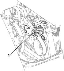
-
Idler arm (Figure 44)
-
PTO driveshaft (Figure 45)
Important: Grease the driveshaft before each use or daily.
-
Axle pivot pin (Figure 46)
-
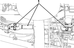
Front of the machine (Figure 47):
-
Attachment pin joints(2)
-
Lift-cylinder bushings (2)
-
Lift-arm pin joints (2)
-
-
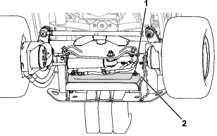
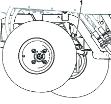
Rear of the machine (Figure 48):
-
Hydraulic-cylinder ball joint (2)
-
Axle spindle hubs (2)
-
Tie-rod ends (2)
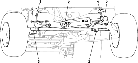
-
Engine Maintenance
Engine Safety
-
Shut off the engine and remove the key before checking the oil or adding oil to the crankcase.
-
Do not change the governor speed or overspeed the engine.
Servicing the Engine Oil
Understanding the Engine-Oil Specifications
Oil Type: Use high-quality, low-ash engine oil that meets or exceeds the following specifications:
-
API service category CJ-4 or higher
-
ACEA service category E6
-
JASO service category DH-2
Crankcase Capacity: Approximately 6.2 L (6.5 US qt) with the filter.
Viscosity: Use the following engine oil viscosity grade:
-
Preferred oil: SAE 15W-40 (above 0°F)
-
Alternate oil: SAE 10W-30 or 5W-30 (all temperatures)
Toro Premium Engine Oil is available from your authorized Toro distributor in either 15W-40 or 10W-30 viscosity grades.
Checking the Engine-Oil Level
| Maintenance Service Interval | Maintenance Procedure |
|---|---|
| Before each use or daily |
|
The best time to check the engine oil is when the engine is cool before it has been started for the day. If the engine has already been run, allow the oil to drain back down to the sump for at least 10 minutes before checking.
If the oil level is at or below the Add mark on the dipstick, add oil to bring the oil level to the Full mark. Do not overfill the engine with oil.
Important: Check the engine oil daily. If the engine-oil level is above the Full mark on the dipstick, the engine oil may be diluted with fuel. If the engine-oil level is above the Full mark, change the engine oil.
Important: Keep the engine-oil level between the upper and lower limits on the dipstick. The engine may fail if you run it with too much or too little oil.
-
Raise the hood; refer to Raising the Hood.
-
Check the engine-oil level; refer to Figure 49.
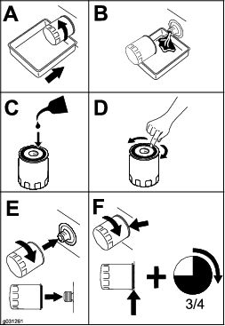
Changing the Engine Oil and Filter
| Maintenance Service Interval | Maintenance Procedure |
|---|---|
| Every 500 hours |
|
-
Start the engine and let it run 5 minutes to allow the oil to warm up.
-
With the machine parked on a level surface, engage the parking brake, shut off the engine, remove the key, and wait for all moving parts to stop before leaving the operating position.
-
Change the engine oil as shown in Figure 50.
-
Change the engine-oil filter as shown in Figure 51.
Note: Ensure that the oil-filter gasket touches the engine, and then an extra 3/4 turn is completed.
Servicing the Air Cleaner
| Maintenance Service Interval | Maintenance Procedure |
|---|---|
| Before each use or daily |
|
| Every 250 hours |
|
Check the air-cleaner body for damage, which could cause an air leak. Replace the body if it is damaged. Check the intake system for leaks, damage, or loose hose clamps
Service the air-cleaner element only when the restriction indicator (Figure 52) requires it. Changing the air cleaner element before it is necessary increases the chance of dirt entering the engine when you remove the element.
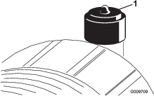
Important: Ensure that the cover is seated correctly and seals with the air-cleaner body and that the latches are closed properly.
Fuel System Maintenance
Danger
Under certain conditions, diesel fuel and fuel vapors are highly flammable and explosive. A fire or explosion from fuel can burn you and others and can cause property damage.
Never smoke when handling fuel, and stay away from an open flame or where a spark may ignite fuel fumes.
Draining Water from the Fuel/Water Separator
| Maintenance Service Interval | Maintenance Procedure |
|---|---|
| Every 50 hours |
|
Drain water from the fuel/water separator as shown in Figure 54.
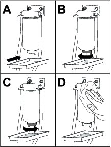
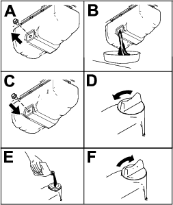
Servicing the Fuel/Water Separator
| Maintenance Service Interval | Maintenance Procedure |
|---|---|
| Every 400 hours |
|
Replace the fuel/water separator as shown in Figure 54.
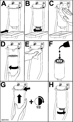
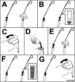
Servicing the Fuel Filter
| Maintenance Service Interval | Maintenance Procedure |
|---|---|
| Every 400 hours |
|
-
Clean the area around the fuel-filter head (Figure 56).
-
Remove the filter and clean the filter head mounting surface (Figure 56).
-
Lubricate the filter gasket with clean lubricating engine oil; refer to the engine owner's manual for additional information.
-
Install the dry filter canister by hand until the gasket contacts the filter head, then rotate it an additional 1/2 turn.
-
Start the engine and check for fuel leaks around the filter head.
Cleaning the Fuel Tank
| Maintenance Service Interval | Maintenance Procedure |
|---|---|
| Yearly |
|
Drain and clean tank if fuel system becomes contaminated or if you store the machine for an extended period. Use clean diesel fuel to flush out the tank.
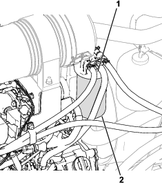
Inspecting the Fuel Lines and Connections
| Maintenance Service Interval | Maintenance Procedure |
|---|---|
| Every 400 hours |
|
Inspect the fuel lines for deterioration, damage, or loose connections.
Electrical System Maintenance
Electrical System Safety
-
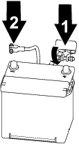
Disconnect the battery before repairing the machine. Disconnect the negative terminal first and the positive last. Connect the positive terminal first and the negative last.
-
Charge the battery in an open, well-ventilated area, away from sparks and flames. Unplug the charger before connecting or disconnecting the battery. Wear protective clothing and use insulated tools.
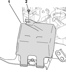
Accessing the Battery
| Maintenance Service Interval | Maintenance Procedure |
|---|---|
| Every 50 hours |
|
The battery is adjacent to the fuel tank on the left side of the machine. To access the battery, raise the hood, unscrew the thumb screw that secures the cover over the battery, and remove the cover (Figure 57).
Note: The screw is retained with a locking washer.
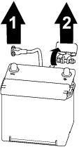
Disconnecting the Battery
Warning
Battery terminals or metal tools could short against metal components, causing sparks. Sparks can cause the battery gasses to explode, resulting in personal injury.
-
When removing or installing the battery, do not allow the battery terminals to touch any metal parts of the machine.
-
Do not allow metal tools to short between the battery terminals and metal parts of the machine.
Warning
Incorrect battery cable routing could damage the machine and cables, causing sparks. Sparks can cause the battery gasses to explode, resulting in personal injury.
Always disconnect the negative (black) battery cable before disconnecting the positive (red) cable.
Connecting the Battery
Warning
Incorrect battery cable routing could damage the machine and cables, causing sparks. Sparks can cause the battery gasses to explode, resulting in personal injury.
Always connect the positive (red) battery cable before connecting the negative (black) cable.
Removing or Installing the Battery
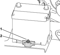
A retainer (Figure 60) holds the battery in the tray. Loosen the retainer hardware to remove the battery; tighten it when installing the battery.
Note: To access the battery, refer to Accessing the Battery. Replace the cover when you install the battery.
Checking the Battery Condition
| Maintenance Service Interval | Maintenance Procedure |
|---|---|
| Every 50 hours |
|
Important: Before welding on the machine, disconnect the negative cable from the battery to prevent damage to the electrical system.
Check the battery condition weekly or after every 50 hours of operation. Keep the terminals and the entire battery case clean, as a dirty battery will discharge slowly.
-
Access the battery; refer to Accessing the Battery.
-
Remove the rubber insulator from the positive terminal and inspect the battery. If the battery is dirty, do the following steps:
-
Wash the entire case with a solution of baking soda and water.
-
Coat both battery posts and cable connectors with Grafo 112X (skin-over) grease (Toro Part No. 505-47) to prevent corrosion.
-
Slide the rubber insulator over the positive terminal.
-
Close the battery cover.
-
Locating the Fuses
Locating the Traction-Unit Fuses
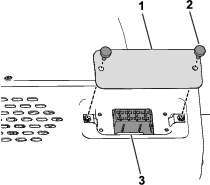
Remove the console cover to access the traction-unit fuses (Figure 61).
Note: The traction-unit fuse decal is located on the other side of the console cover.
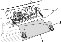
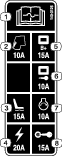
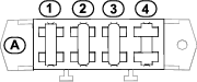
Refer to the Traction-Unit Fuse Block table for a description of each fuse on the traction-unit fuse block (Figure 62):
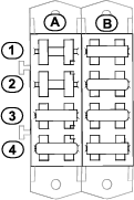
| A | B | |
| 1 | Cab (10 A) | Display-screen power (15 A) |
| 2 | Open slot | Key run input for the display-screen controller (10 A) |
| 3 | Air ride seat (15 A) | Start circuit (10 A) |
| 4 | USB port, hour meter, telematics, expansion port (20 A) | Ignition switch power (15 A) |
Locating the Cab Fuses
The cab fuses are located above the passenger seat. Access the fuses by removing the fuse-box cover (Figure 63).
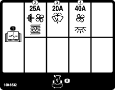
Refer to the Cab Fuse Block table for a description of each fuse on the traction-unit fuse block (Figure 64):
| A | |
| 1 | Condenser fan; Air-conditioning clutch (25 A) |
| 2 | Windshield washer (20 A) |
| 3 | Fan and interior light (40 A) |
| 4 | Open slot |
Drive System Maintenance
Torquing the Wheel-Lug Nuts
| Maintenance Service Interval | Maintenance Procedure |
|---|---|
| After the first hour |
|
| After the first 10 hours |
|
| Every 200 hours |
|
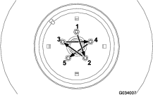
Wheel-lug nut torque specification: 102 to 108 N∙m (75 to 80 ft-lb)
Torque the lug nuts at the front and rear wheels (4-wheel-drive machines only) in the pattern as shown in Figure 65 and Figure 66 to the specified torque.

Aligning the PTO Driveshaft
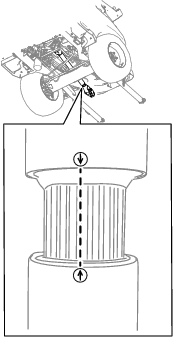
If you separate the PTO-driveshaft telescoping end the from the clutch end, ensure that the arrows align (Figure 67) when you install the telescoping end.
Important: If the arrows on the driveshaft are not aligned, severe imbalance may occur in the driveline system.
Cooling System Maintenance
Cooling System Safety
-
Swallowing engine coolant can cause poisoning; keep out of reach from children and pets.
-
Discharge of hot, pressurized coolant or touching a hot radiator and surrounding parts can cause severe burns.
-
Always allow the engine to cool at least 15 minutes before removing the radiator cap.
-
Use a rag when opening the radiator cap, and open the cap slowly to allow steam to escape.
-
-
Do not operate the machine without the covers in place.
-
Keep your fingers, hands and clothing clear of rotating fan and drive belt.
Coolant Specifications
The engine coolant must conform to the following specifications:
-
JIS K-2234 (Japanese industrial standard)
-
SAE J814 (engine coolants)
-
ASTM D3306 (specification for ethylene-glycol base engine coolant)
Use one of the following coolant blends:
-
Glycol-based pre-diluted coolant (50/50 blend)
-
Glycol-based coolant mixed with distilled water (50/50 blend)
-
Glycol-based coolant mixed with good quality water (50/50 blend)
-
Total hardness <170 ppm
-
Chloride <40 ppm (CI)
-
Sulfates <100 ppm (SO4)
-
Checking the Cooling System and Coolant Level
| Maintenance Service Interval | Maintenance Procedure |
|---|---|
| Before each use or daily |
|
| Every 1,500 hours |
|
Warning
If the engine has been running, the radiator pressurizes and the coolant inside is hot. If you remove the cap, coolant may spray out, causing severe burns.
-
Do not remove the expansion-tank cap to check coolant levels.
-
Do not remove the expansion-tank cap when the engine is hot. Allow the engine to cool for at least 15 minutes or until the radiator cap is cool enough to touch without burning your hand.
When the engine is cold, the coolant level should be no higher than the COLD mark on the side of the expansion tank (Figure 68). When the engine is warm, the coolant level should be no higher than the FULL (HOT) mark.
If the coolant is above the COLD mark when the engine is cold, it may leak out of the tank when the engine gets hot during operation.
-
When the engine is cold, check the level of the coolant in the expansion tank.
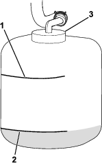
-
If the coolant is not visible at the COLD mark or below when cold, remove the expansion-tank cap and add the recommended replacement coolant [refer to Coolant Specifications] as required to bring the level to the COLD mark.
Important: Do not use water only or alcohol-based coolants.Do not fill past the COLD mark on the tank.
-
Install the expansion-tank cap.
Checking the Hood-Air-Intake Screen
| Maintenance Service Interval | Maintenance Procedure |
|---|---|
| Every 50 hours |
|
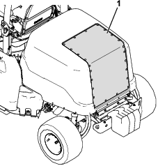
-
Raise the hood; refer to Raising the Hood.
-
Use compressed air to clean the hood screen (shown in Figure 69). Direct the air out from the machine.
Checking the Cooling Fins
| Maintenance Service Interval | Maintenance Procedure |
|---|---|
| Every 50 hours |
|
| Every 250 hours |
|
-
Use compressed air to clean the radiator fins. Direct the air out from the machine (Figure 70).
Important: Do not use water to clean the fins.
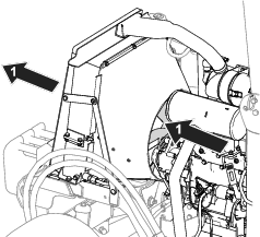
-
Straighten any bent fins.
Inspecting the Cooling-System Hoses
| Maintenance Service Interval | Maintenance Procedure |
|---|---|
| Every 200 hours |
|
Inspect the cooling-system hoses for leaks, kinked lines, loose mounting supports, wear, loose fittings, weather deterioration, and chemical deterioration. Make all necessary repairs before operating the machine.
Brake Maintenance
Checking and Adjusting the Parking Brake
| Maintenance Service Interval | Maintenance Procedure |
|---|---|
| Every 400 hours |
|
Checking the Parking Brake
-
Place jack stands under the front of the machine; refer to Raising the Front of the Machine.
-
Remove the front wheels.
-
Move the parking brake to the DISENGAGED position; refer to Parking Brake.
-
Remove the brake drums (Figure 71) by hand.
-
If you feel resistance while removing the brake drums by hand, an adjustment is not needed.
-
If you do not feel resistance while removing the brake drums by hand, an adjustment is needed; refer to Adjusting the Parking Brake.
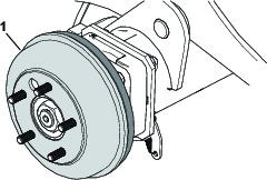
-
-
Install the front wheels and torque the lug nuts; refer to Torquing the Wheel-Lug Nuts.
Adjusting the Parking Brake
-
Chock the wheels.
-
Ensure that the parking brake is disengaged.
-
Locate the brake-cable mount (Figure 72) under the left side of the machine near the left wheel.
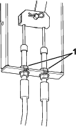
-
Loosen the top jam nuts so that a gap (3.2 mm [1/8 inch] to 4.8 mm [3/16 inch]) appears.
-
Pull down on a cable until the top jam nut contacts the bracket.
-
Tighten the bottom jam nut.
-
Repeat steps 5 and 6 for the other cable.
-
Check the parking brake; refer to Checking the Parking Brake.
Belt Maintenance
Checking the Alternator-Belt Tension
| Maintenance Service Interval | Maintenance Procedure |
|---|---|
| After the first 10 hours |
|
| After the first 50 hours |
|
| Every 100 hours |
|
Proper tension of the belt allows 10 mm (3/8 inch) of deflection when a force of 4.5 kg (10 lb) is applied on the belt midway between the pulleys.
If the deflection is not 10 mm (3/8 inch), perform the following steps:
-
Loosen the alternator-mounting bolt (Figure 64).
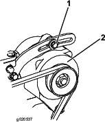
-
Increase or decrease the alternator-belt tension and tighten the bolt.
-
Check the deflection of the belt again to ensure that the tension is correct.
Servicing the Traction Belt
Checking the Traction Belt
| Maintenance Service Interval | Maintenance Procedure |
|---|---|
| Every 100 hours |
|
Inspect the traction belt for signs of excessive wear or damage.
Replace the belt if it is excessively worn or damaged; refer to Replacing the Traction Belt.
Replacing the Traction Belt
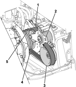
Removing the Traction Belt
-
Disconnect the PTO shaft from the attachment gearbox; refer to your attachment Operator’s Manual.
-
Unplug the clutch-wire-harness connector from the machine wire harness (Figure 75).
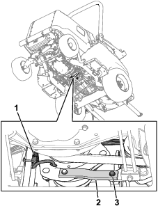
-
Remove the bolt, washer, and nut from the rubber strap (Figure 75) on the frame.
A spacer is contained in the rubber strap; ensure that this is not misplaced.
-
Have an assistant use a ratchet to release tension from the belt, then remove the belt from the pump pulley, idler pulley, and engine pulley.
-
Move the belt over the clutch and forward on the PTO shaft.
Installing the Traction Belt
-
Move the belt along the PTO shaft, over the clutch, and onto the engine pulley.
-
Have an assistant use a ratchet to pull the idler pulley down.
-
Route the belt on the engine pulley, idler pulley, and pump pulley (Figure 74).
-
Remove the ratchet from the idler arm.
-
Ensure that the rubber-strap spacer is in-place.
-
Use the previously removed bolt, washer, and nut to secure the end of the rubber strap to the frame.
-
Plug in the clutch-wire-harness connector to the machine wire harness.
Controls System Maintenance
Adjusting the PTO-Clutch Gap
| Maintenance Service Interval | Maintenance Procedure |
|---|---|
| Every 200 hours |
|
-
Allow the engine to cool.
-
Raise the engine hood.
-
Adjust the air gap so that a 0.3 mm (0.012 inch) feeler gauge slides in between the clutch lining and friction plate with light pressure (Figure 76).
Note: You can decrease the gap by turning the adjusting nuts clockwise (Figure 76). The maximum service gap is 0.6 mm (0.024 inch). Adjust all 3 air gaps to 0.4 mm (0.012 inches).
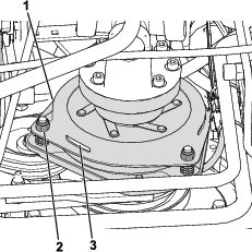
-
After the 3 air gaps are adjusted, check all 3 again.
Note: Adjusting 1 air gap can alter the other gaps.
Adjusting the Traction-Pedal Stop
You can adjust the traction pedal for operator comfort or to reduce the maximum forward speed of the machine.
-
Move the traction pedal fully forward (Figure 77).
Note: The traction pedal should contact the traction-pedal stop before the pump reaches full stroke.
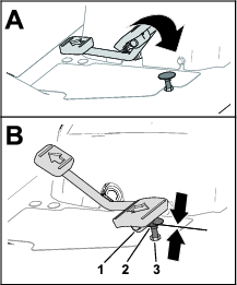
-
If the traction pedal does not contact the traction-pedal stop or if you want to reduce the forward speed of the machine, perform the following:
-
Hold the traction-pedal stop (Figure 77) with a wrench.
-
Loosen the jam nut at the bottom of the footrest plate (Figure 78).
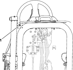
-
Move the traction pedal to the full forward position (Figure 77).
-
While holding the traction-pedal stop, adjust the jam nut that is above the footrest plate (Figure 77) until the traction pedal makes contact with the stop.
-
Lengthen the traction-pedal stop position by rotating the stop 1 full rotation counterclockwise away from the jam nut above the footrest plate.
Note: Shortening the traction-pedal-stop position will increase the forward speed of the machine.
-
While holding the traction-pedal stop, torque the jam nut at the bottom of the footrest plate (Figure 77 and Figure 78) to 37 to 45 N∙m (27 to 33 ft-lb).
-
Check that the traction pedal contacts the traction-pedal stop before the pump reaches full stroke.
Note: If the traction pedal does not contact the traction-pedal stop, repeat steps 1 through 7.
-
Hydraulic System Maintenance
Hydraulic System Safety
-
Seek immediate medical attention if fluid is injected into skin. Injected fluid must be surgically removed within a few hours by a doctor.
-
Ensure that all hydraulic-fluid hoses and lines are in good condition and all hydraulic connections and fittings are tight before applying pressure to the hydraulic system.
-
Keep your body and hands away from pinhole leaks or nozzles that eject high-pressure hydraulic fluid.
-
Use cardboard or paper to find hydraulic leaks.
-
Safely relieve all pressure in the hydraulic system before performing any work on the hydraulic system.
Hydraulic Fluid Specifications
The reservoir is filled at the factory with approximately 22.7 L (6 US gallons) of high-quality hydraulic fluid. Check the level of the hydraulic fluid before the engine is first started and daily thereafter; refer to Checking the Hydraulic-Fluid Level.
Recommended replacement fluid: Toro PX Extended Life Hydraulic Fluid; available in 19 L (5 US gallon) pails or 208 L (55 US gallon) drums.
Note: A machine using the recommended replacement fluid requires less frequent fluid and filter changes.
Alternative hydraulic fluids:If Toro PX Extended Life Hydraulic Fluid is not available, you may use another conventional, petroleum-based hydraulic fluid having specifications that fall within the listed range for all the following material properties and that it meets industry standards. Do not use synthetic fluid. Consult with your lubricant distributor to identify a satisfactory product.
Note: Toro does not assume responsibility for damage caused by improper substitutions, so use products only from reputable manufacturers who will stand behind their recommendation.
| Material Properties: | ||
| Viscosity, ASTM D445 | cSt @ 40°C (104°F) 44 to 48 | |
| Viscosity Index ASTM D2270 | 140 or higher | |
| Pour Point, ASTM D97 | -37°C to -45° C (-34° F to -49° F) | |
| Industry Specifications: | Eaton Vickers 694 (I-286-S, M-2950-S/35VQ25 or M-2952-S) | |
Note: Many hydraulic fluids are almost colorless, making it difficult to spot leaks. A red dye additive for the hydraulic fluid is available in 20 ml (2/3 fl oz) bottles. A bottle is sufficient for 15 to 22 L (4 to 6 US gallons) of hydraulic fluid. Order Part No. 44-2500 from your authorized Toro distributor.
Important: Toro Premium Synthetic Biodegradable Hydraulic Fluid is the only synthetic biodegradable fluid approved by Toro. This fluid is compatible with the elastomers used in Toro hydraulic systems and is suitable for a wide-range of temperature conditions. This fluid is compatible with conventional mineral oils, but for maximum biodegradability and performance, the hydraulic system should be thoroughly flushed of conventional fluid. The oil is available in 19 L (5 US gallons) pails or 208 L (55 US gallons) from your authorized Toro distributor.
Checking the Hydraulic-Fluid Level
| Maintenance Service Interval | Maintenance Procedure |
|---|---|
| Before each use or daily |
|
-
Park the machine on a level surface, lower the cutting unit, engage the parking brake, shut off the engine, and remove the key.
-
Remove the plug from the hydraulic tank (Figure 79).
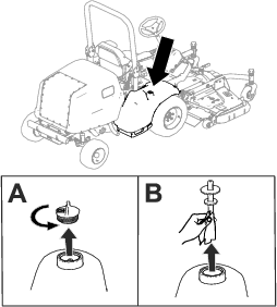
-
Remove the dipstick from the hydraulic tank and wipe it with a clean cloth (Figure 79).
-
Insert the dipstick into the hydraulic tank.
-
Remove the dipstick and check the fluid level (Figure 80).
-
If you have a cutting unit equipped: The hydraulic-fluid level is at the appropriate level when the fluid appears between the lower 2 marks on the dipstick (A in Figure 80). It is also acceptable for the fluid level to be above the lower marks.
-
If you have the auxiliary hydraulic kit equipped: The hydraulic-fluid level is at the appropriate level when the fluid appears between the upper 2 marks on the dipstick (B in Figure 80).
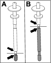
-
-
If the fluid level is below the appropriate lower mark (per your equipped attachment; refer to step 5) on the dipstick, add the specified hydraulic fluid into the tank. Repeat steps 3 through 5 until the fluid level appears between the appropriate 2 marks on the dipstick.
-
Insert the dipstick and plug into the hydraulic tank.
-
Hand-tighten the plug.
Important: Do not use a tool to tighten the plug.
-
Check all hydraulic hoses and fittings for leaks.
Changing the Hydraulic Fluid and Filters
| Maintenance Service Interval | Maintenance Procedure |
|---|---|
| After the first 1000 hours |
|
| Every 800 hours |
|
| Every 1,000 hours |
|
| Every 2,000 hours |
|
If the hydraulic fluid becomes contaminated, contact your authorized Toro distributor; the system must be flushed. Contaminated fluid looks milky or black when compared to clean fluid.
Important: Use Toro replacement filters; refer to the machine Parts Catalog. Using any other filter may void the warranty on some components.
-
Park the machine on a level surface, lower the cutting unit, engage the parking brake, shut off the engine, and remove the key.
-
Place a large drain pan under the hydraulic-fluid tank.
-
Remove the hydraulic-tank cap and dipstick.
-
Remove the drain plug (Figure 81) from the bottom of the tank and let the hydraulic fluid flow into the pan.
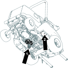
-
Clean the area around the filter-mounting area.
-
Place a drain pan under the filter (Figure 81), remove the filter, and let any remaining oil drain into the pan.
-
Lubricate the new filter gasket and fill the filter with hydraulic fluid.
-
Ensure that the filter-mounting area is clean and screw the filter on until the gasket contacts the mounting plate; then tighten the filter an additional 1/2 turn.
-
Fill the hydraulic tank with hydraulic fluid; refer to Checking the Hydraulic-Fluid Level.
Important: Use only the hydraulic fluids specified. Other fluids could cause system damage.
-
Install the drain plug when the hydraulic fluid stops draining.
-
Install the reservoir dipstick and cap.
-
Start the engine and use all of the hydraulic controls in the following order to distribute hydraulic fluid throughout the system:
-
Use the traction pedal to move the machine forward and backward.
-
Use the steering wheel to move the tires all the way to the right and left.
-
Use the lift switch to raise and lower the attachment (e.g., cutting unit).
-
-
Check for leaks and shut off the engine.
-
Check the hydraulic fluid level in the tank; refer to Checking the Hydraulic-Fluid Level.
Checking the Hydraulic Lines and Hoses
| Maintenance Service Interval | Maintenance Procedure |
|---|---|
| Every 2 years |
|
Inspect the hydraulic lines and hoses daily for leaks, kinked lines, loose mounting supports, wear, loose fittings, weather deterioration, and chemical deterioration. Make all necessary repairs before operating the machine.
Cab Maintenance
Cleaning the Cab
Important: Use care around the cab seals (Figure 82). If you are using a pressure washer, keep the washer wand at least 0.6 m (2 ft) away from the machine. Do not use the pressure washer directly on the cab seals or under the rear overhang.
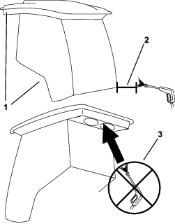
Cleaning the Cab Air Filters
| Maintenance Service Interval | Maintenance Procedure |
|---|---|
| Every 400 hours |
|
-
Remove the knobs and grates from the cab rear overhang (Figure 83).
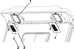
-
Remove the air filters from the cab.
-
Clean the filters by blowing clean, oil-free, compressed air through them.
Important: If either filter has a hole, tear, or other damage, replace the filter.
-
Use the knobs and grates to install the filters into the cab (Figure 83).
Cleaning the Cab Condenser Filter
The purpose of the cab condenser filter is to prevent large debris, such as grass and leaves, from entering the cab condenser and condenser fans.
-
Pull the screen cover straight down.
-
Clean the condenser filter with water.
Note: Do not use a pressure washer.
Important: If the filter has a hole, tear, or other damage, replace the filter.
-
Allow the filter to dry before installing it into the machine.
-
Rotate the filter screen around the tabs until the latch locks into the latch-mount assembly (Figure 84).
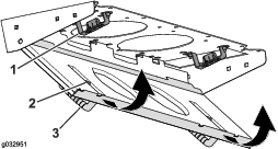
Replacing the Dome Light
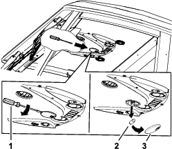
Filling the Windshield-Wiper-Fluid Reservoir
Note: The windshield-wiper-fluid reservoir is located next to the engine on the right side of the machine.
-
Remove the cap (Figure 86) on the reservoir.
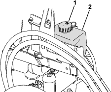
-
Fill the reservoir with wiper fluid.
-
Replace the cap on the reservoir.
Storage
Storage Safety
-
Shut off the engine, remove the key, and wait for all movement to stop before you leave the operator’s position. Allow the machine to cool before adjusting, servicing, cleaning, or storing it.
-
Do not store the machine or fuel container where there is an open flame, spark, or pilot light, such as on a water heater or other appliance.
Preparing the Machine
Important: Do not use brackish or reclaimed water to clean the machine.
-
Park the machine on a level surface; engage the parking brake; shut off the engine; remove the key; and wait for all movement to stop before leaving the machine.
-
Thoroughly clean the machine, cutting unit, and engine.
Important: Do not use high-pressure water near the electrical controls or cab seals, as this may cause damage.
-
Check and adjust the air pressure in the tires; refer to Checking the Tire Air Pressure.
-
Check the hydraulic lines and hoses; repair them as necessary.
-
Check the hydraulic-fluid level; refer to Checking the Hydraulic-Fluid Level.
-
Remove, sharpen, balance, and install the cutting-unit blades.
-
Check for loose fasteners and tighten them as necessary.
-
Lubricate all grease fittings and apply oil to pivot points. Wipe clean any excess lubricant.
-
Lightly sand and use touch-up paint on painted areas that are scratched, chipped, or rusted. Repair any dents in the metal body.