Installation
Preparing the Machine
-
Park the machine on a level surface.
-
Engage the parking brake.
-
Shut off the engine and remove the key.
-
Disconnect first the negative cable, then the positive cable from the battery.
Removing the Existing Wheel
-
Chock both front wheels to prevent the machine from moving.
-
Use a jack or hoist to lift the rear of the traction unit by the hoop welded on the caster fork, and remove the tire assembly from the caster fork.
-
Place appropriate jackstands beneath the frame to support the raised machine.
-
Remove the wheel hub assembly from the tire assembly.
Retain the lug nuts.
-
Remove the adapter plates from the caster fork.
Modifying the Caster Fork
If the traction unit has a serial number prior to 269999999, you must modify the caster wheel fork. To modify the caster wheel fork, you must obtain a drill guide (Toro Part No. 112-0256-01) from an authorized Toro distributor. If you do not need to modify the caster wheel fork, proceed to Installing the Motor and Hub Assembly.
-
Mount the drill guide to the right side of the caster fork with 2 bolts (5/16 x 3 inches), 4 washers, and 4 nuts (Figure 1).
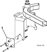
-
Using the remaining hole in the drill guide, enlarge the hole in the caster fork to 9/16 inch (14 mm) diameter.
Important: Use a new or recently sharpened 9/16 (14 mm) inch drill bit. Proceed slowly when drilling. Do not use excessive force when drilling to prevent jamming the drill.
-
Move the fasteners to the other holes in the drill guide, and repeat the process until all 3 holes are enlarged.
Installing the Motor and Hub Assembly
Parts needed for this procedure:
| Motor and hub assembly | 1 |
| Re-lube flangette | 1 |
| Standard flangette | 1 |
| Bearing | 1 |
| Socket-head screw | 2 |
| Locknut (1/2 inch) | 2 |
| Hardened washer | 3 |
| Spacer | 1 |
| Adapter plate | 1 |
| Hex-head bolt | 3 |
| Decal | 2 |
-
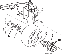
Mount the 2 fittings (45°) to the side of the motor assembly (Figure 2).
Note: Ensure that all O-rings are lubricated and in position before installing the fittings.
-
Remove the grease fitting from the new motor and hub assembly (Figure 2).
-
Mount the tire assembly to the motor and hub assembly with the 4 lug nuts that you previously removed.
Note: Torque the lug nuts to 70 to 90 ft-lb (95 to 122 N∙m).
-
Install the grease fitting to the hub assembly, pointing it away from the hub.
-
Insert the flangettes and bearing onto the end of the motor shaft as shown in Figure 2.
-
Position the motor hub, flangettes with bearing, adapter plate, and tire assembly into the caster fork.
Note: Ensure that the motor is oriented with the hydraulic fittings to the rear of the machine (Figure 2).
-
Loosely secure the motor to the inside of the caster fork with 2 socket-head screws and 2 locknuts (Figure 2).
Note: Tighten the screws to 100 ft-lb (135 N∙m).
-
Loosely assemble the flangettes (with the bearing to the inside of the caster fork) with 3 hex-head bolts (3/8 x 2-1/4 inches), an adapter bearing plate, a spacer mount, 3 hardened washers, and 3 locknuts (3/8 inch).
Important: Ensure that there is no radial load on the motor shaft.
Note: The grease fitting must be in the downward position on the flangette (Figure 2).
-
Torque the flangette screws to 40 ft-lb (55 N∙m).
Important: Failing to carefully follow the above assembly sequence may result in premature motor seal and bearing failure.
-
Apply a thread-locking adhesive (such as Loctite®) to bearing set screws.
Note: Torque the set screws to 80 to 100 in-lb (9 to 11 N∙m).
-
Verify overrunning bearing operation: The tire should roll freely forward, but the wheel motor will engage when the tire is rolled backward.
-
Lower the rear of the traction unit to the ground.
-
Grease all the fittings with No. 2 general purpose lithium-based grease.
-
Apply a 3-wheel-drive decal to each side of the caster fork (Figure 2).
Installing the Hoses
Parts needed for this procedure:
| Self-tapping screws | 4 |
| Tube clamp | 4 |
| Coverplate | 2 |
| Hex-head screw (M8) | 2 |
| Locknut (M8) | 2 |
| Hose assembly (95-0517) | 1 |
| Hose assembly (100-6412) | 1 |
| Hose clamp bracket | 2 |
| Cable tie | 1 |
-
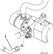
Drain all the hydraulic fluid from the reservoir by removing the upper hose from the pump (Figure 3).

-
Connect the hose after draining the hydraulic fluid.
Note: The hydraulic system capacity is approximately 8.5 US gallons (33 L).
Important: Take care not to contaminate the hydraulic fluid if you are going to reuse it. A very small amount of debris can severely damage the hydraulic system.
-
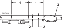
Refer to the dimensions shown in Figure 4 to locate, mark, and drill 4 holes (9/32 inch or 7 mm diameter) into the right-hand frame tube.
-
Secure the hose clamp bracket assemblies (tube clamps, cover plates, clamp brackets, hex-head screws, and locknuts) to the frame with 4 self-tapping screws (Figure 5).
-
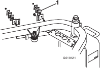
Disconnect the lower hydrostat hose from the hydrostat (Figure 6) and from the upper-bulkhead tee fitting to the front-wheel motors (Figure 7).
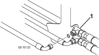
Note: Remove and discard the lower hydrostat hose.
-
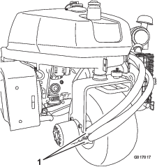
Connect the 90° fitting end of the new (shortest) hose to the lower port of the hydrostat.
-
Route the hose through the lower position in the hose clamps, behind the caster fork and to the lower port of the rear-wheel motor.
Note: Mount the bottom hose ends horizontally (Figure 8).
-
Secure the hose ends to the fittings.
Note: Use a backing wrench to ensure that the hose does not twist.
-
Secure the hoses together at the rear of the unit with a cable tie.
-
Turn the steering fork fully side-to-side to check for proper hose flex and position.
Note: The hoses should not rub on the tire, rim, tanks, steering fork, or steering hoses.
Note: The hydraulic lines must not be twisted, kinked, have sharp bends, or touch sharp edges, moving parts, or engine exhaust parts.
-
Secure the hoses in the brackets.
Note: The hose clamp brackets are slotted vertically to allow for adjustment.
-
Grease all fittings with No. 2 lithium grease.
Completing the Installation
-
Check the hydraulic-fluid level; refer to your traction unit Operator’s Manual.
-
Connect the positive cable to the battery.
-
Connect the negative cable to the battery.
-
Start the engine.
-
Cycle the traction and lift cylinders to purge the air from the hydraulic system.
-
Check the hydraulic-fluid level.