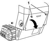
Installation
Preparing the Machine
-
Park the machine on a level surface.
-
Engage the parking brake.
-
Lower the loader arms.
-
Shut off the engine and remove the key.
-
Open or remove the hood, as applicable for your machine.
-
Remove the negative (-) battery cable from the battery.
Removing the Access Panels
Removing the Fuse Panel
-
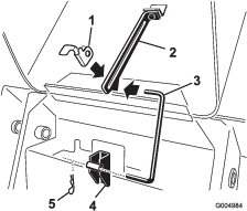
Pull the hairpin cotter from the bottom end of the hood prop-rod and slide the prop rod out of the retaining brackets and the prop-rod tab.
-
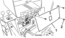
Remove the 4 screws securing the fuse panel and then pull the panel out and up to remove it.
Installing the Lights
Parts needed for this procedure:
| Light | 2 |
| Carriage bolt (5/16 x 1 inch) | 2 |
| Flat washer | 4 |
| Rubber grommet | 2 |
| Nut (5/16 inch) | 6 |
| Left light bracket | 1 |
| Right light bracket | 1 |
| Thread-forming bolt (5/16 x 3/4 inch) | 4 |
| Curved washer (320-D or 323 traction unit only) | 2 |
320-D or 323 Traction Units
Note: Only 2 thread-forming bolts are needed when installing the kit on 320-D or 323 traction units.
-
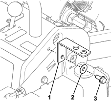
Install the right light bracket.
-
Install a light to the outer hole of the bracket.
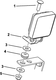
-
Install the left light bracket.
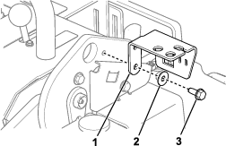
-
Install the other light and the switch to the bracket.
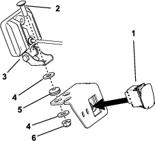
TX 427 or TX 525 Traction Units
-
Install the right bracket.
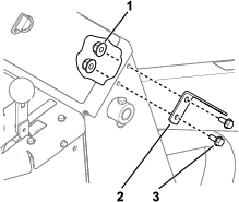
-
Install a light to the bracket.

-
Install the left light bracket.
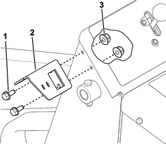
-
Install the other light and the switch to the bracket.

Routing the Wire Harness
Parts needed for this procedure:
| Wire harness | 1 |
| Cable tie | 2 |
320-D or 323 Traction Units

-
Connect the wire harness to the left light and switch.
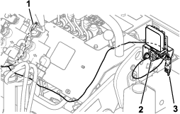
-
Route the wire harness inside the left operator grip and then in front of the control panel, behind the hoses.
-
Connect the wire harness to the machine wire harness (P06).
-
Route the wire harness behind the hoses and inside the right operator grip.
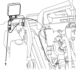
-
Connect the right light.
-
Secure the wire harness to the left light bracket.
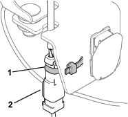
-
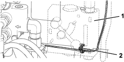
Secure the wire harness to the bottom flow divider hose (320-D traction units only) or to the front, left side of the control panel.
TX 427 or TX 525 Traction Units

-
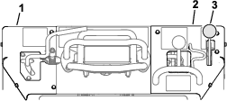
Remove the brake-lever knob.
-
Remove the left and right control panel covers.
-
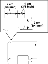
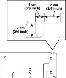
Cut a slot in both control panel covers as shown.
Warning
Using a drill without proper eye protection may allow debris to enter the eye, causing injury.
When drilling or carrying out other operation, always wear eye protection.
-
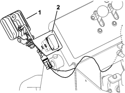
Connect the wire harness to the left light and switch.
-
Route the wire harness into the control panel and through the opening in the frame toward the engine compartment.
-
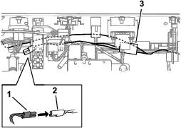
Route the wire harness across the front of the machine and connect the wire harness to the machine wire harness (P09).
-
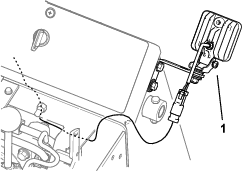
Route the wire harness back to the control panel and connect it to the right light.
-
Install the left and right control panel covers, ensuring that the wire harness goes through the notches (see Figure 18).
-
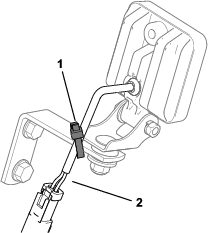
Secure the wire harness to the left light bracket.

-
Secure the wire harness to the right light bracket.
Completing the Installation
Parts needed for this procedure:
| Fuse (10 A)—525 traction unit only | 1 |
-
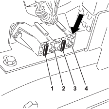
For the TX 525, perform the following steps:
-
Install the fuse (10 A) to the fuse-block location shown in Figure 26.
-
Install the fuse and rear panels.
Note: Reverse the procedures for each panel as shown in Removing the Access Panels.
-
-
Install the negative (-) battery cable to the battery.
-
Close or install the hood, as applicable for your machine.
-
Start the machine and verify that the lights function using the switch.
