Installation
Preparing the Machine
-
Park the machine on a level surface.
-
Engage the parking brake.
-
Lower the cutting units.
-
Shut off the engine and remove the key.
-
Wait for all movement to stop before leaving the operator’s seat.
-
Allow the machine components to cool.
-
Remove the right, rear cutting unit from the lift arm, and move the cutting unit near the right rear tire.
Important: Do not disconnect the hydraulic hoses.
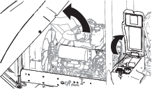
Opening the Hood and Battery Storage Box
Checking the Battery
-
Inspect the battery in the machine to ensure that the battery is a BCI Group 24 automotive type.
Important: To correctly install the positive battery cable kit, the machine must have a BCI Group 24 automotive battery. If the battery in the machine is not a BCI Group 24 automotive battery, replace the battery.
-
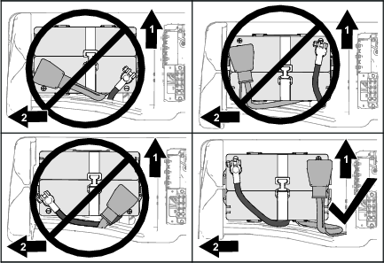
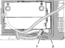
Check that the battery (Figure 2) is installed in the machine correctly:
-
The positive and negative battery posts must align toward the front of the machine.
-
The negative battery post must align toward the centerline of the machine.
Important: If the battery is not installed to the machine correctly, remove the battery and install it with the negative battery post aligned forward and toward the centerline of the machine.
-
-
Check that the battery strap is installed, undamaged, and used to secure the battery to the battery storage box.
Note: If the battery strap is worn or damaged, replace the strap.
-
Inspect the battery cable routing, and ensure that cable ties secure the battery cables.
Disconnecting the Battery
Warning
Battery terminals or metal tools could short against metal components, causing sparks.
-
When removing or installing the battery, do not allow the battery terminals to touch any metal parts of the machine.
-
Do not allow metal tools to short between the battery terminals and metal parts of the machine.
-
Always keep the battery strap in place to protect and secure the battery.
Warning
Electrical sparks can cause the battery gasses to explode, resulting in personal injury.
Incorrect battery cable routing could damage the machine and cables, causing sparks.
-
Always disconnect the negative (black) battery cable before disconnecting the positive (red) cable.
-
Always connect the positive (red) battery cable before connecting the negative (black) cable.
-
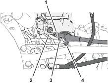
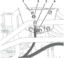
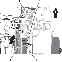
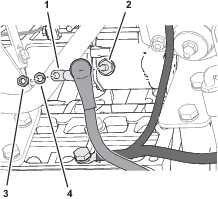
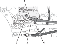
Loosen the nut and T-bolt that secure the negative battery-cable clamp to the battery post, and remove the cable from the post (Figure 3).
-
Lift the insulator of the positive battery cable and slide it rearward (Figure 3).
-
Remove the nut that secures the ring terminals of the machine wire harness to the double ended battery-clamp stud on the positive battery cable, and remove the ring terminal (Figure 3).
-
Remove the nut and double ended battery-clamp stud that secure the positive battery-cable clamp to the battery post, and remove the cable from the post (Figure 3).
-
Remove the wires and ring terminals of the machine wire harness from the insulator of the positive battery cable (Figure 3).
Note: Retain the double ended battery-clamp stud and nuts for installation of the new positive battery cable.
Preparing the Battery Posts and Negative Battery-Cable Clamp
Cleaning the Battery Posts
Clean both battery posts of corrosion, dirt, and grease.
Cleaning the Negative Battery-Cable Clamp
Clean negative battery-cable clamp, T-bolt, and nut of corrosion, dirt, and grease.
Removing the Positive Battery Cable from the Machine
-
Cut and remove any cable ties that secure the positive battery cable.
-
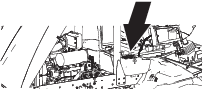
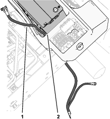
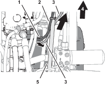
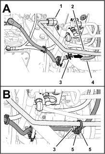
At the starter, slide the cover of the battery cable away from the starter (Figure 4 or Figure 5, and Figure 6).
-
Remove the nut and lock washer that secure the battery cable to the terminal stud of the starter, and remove the cable from the stud (Figure 6).
Note: Retain the nut and lock washer.
-
Clean the starter-terminal stud, lock washer, and nut of corrosion, dirt, and grease.
-
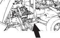
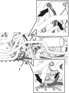
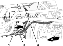
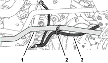
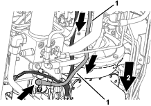
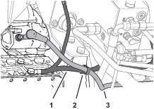
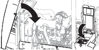
Thread the positive battery cable between the hydraulic hoses and the gear pump, up and out the battery storage box (Figure 7).
Note: Discard the old positive battery cable.
Checking the Negative Battery Cable Routing
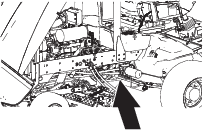
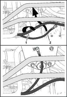
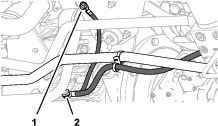
Check that the routing of the negative battery cable is the same as shown in Figure 8.
Important: Ensure that the negative battery cable is routed so that it does not contact any sharp edge or directly contacts any hydraulic components. Ensure that the battery cable does not hang in loose loops or contacts moving components like the cutting unit.
Note: If the negative battery cable routing is not correct, adjust the battery cable routing as shown in Figure 8. You will secure the negative battery cable to the positive battery cable in Securing the Positive Battery Cables.
Replacing the Negative Battery Cable
Parts needed for this procedure:
| Negative battery cable | 1 |
| Double-loop cable tie | 1 |
Removing the Negative Battery Cable
-
Cut and remove any cable ties that secure the negative battery cable.
-
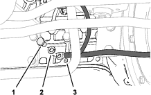
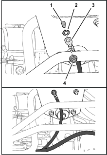
At the right engine-mount bracket, remove the flange locknut (3/8 inch) that secures the chassis ground-branch terminal of the negative battery cable and external tooth-lock washer to the mount bracket (Figure 9).
Note: Do not remove the flange-head bolt.
-
Clean corrosion, dirt, and grease from the flange locknut, external tooth-lock washer, and engine-mount bracket.
-
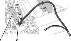
Remove the capscrew (12 x 25 mm) and lock washer (12 mm) that secure the negative battery-cable terminal to the engine (Figure 10).
-
Clean corrosion, dirt, and grease from the capscrew, lock washer, and ground-contact surface of the engine.
-
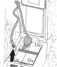
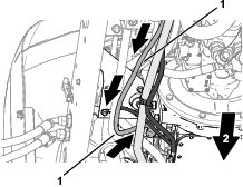
Thread the negative battery cable down and out the battery storage box, and remove the cable from the machine (Figure 11).
Note: Discard the old negative battery cable.
Routing the Negative Battery Cable
Click here to view the Negative Battery Cable animation
Important: Route the negative battery cable so that it does not contact any sharp edge or directly contacts any hydraulic components. Ensure that the battery cable does not hang in loose loops or contacts moving components like the cutting unit.

-
Route the terminal clamp of the new negative battery cable through the slot in the bottom of the battery storage box (Figure 12).
-
Route the negative battery cable along the battery (Figure 13).
-
Route the terminal (1/0 AWG) to the ground-contact surface of the engine (Figure 14).
-
Loosely assemble the terminal to the engine (Figure 15) with the capscrew (12 x 25 mm) and lock washer (12 mm).
-
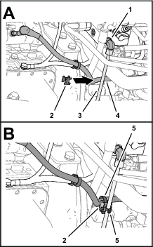
Route the chassis ground-branch terminal (4-6 AWG) of the negative battery cable between the engine and the engine ground branch, and up toward the engine-mount bracket (Figure 16).
-
Assemble the external tooth-lock washer and terminal (4-6 AWG) of the chassis ground branch onto the capscrew (Figure 17).
-
Loosely assemble the terminal and external tooth-lock washer to the engine-mount bracket with the flange locknut and capscrew (Figure 17).
Securing the Negative Battery Cable
-
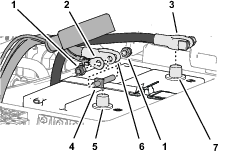
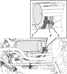
Secure the engine ground branch of the negative battery cable to the rear hydraulic-motor tube—25 mm (1 inch) with a double-loop cable tie as shown in Figure 17.
Important: Ensure that the cable tie secures the battery cable to the hydraulic-motor tube.
-
Torque the capscrew and locknut at the engine-mount bracket (Figure 19) to 37 to 45 N∙m (37 to 33 ft-lb).
-
Torque the capscrew (Figure 19) at the engine to 80 to 100 N∙m (59 to 73 ft-lb).
Assembling the Positive Battery Cable to the Machine
Parts needed for this procedure:
| Positive battery cable | 1 |
| Double-loop cable tie (Groundsmaster machines) | 2 |
| Double-loop cable tie (Reelmaster machines) | 1 |
| Swivel-saddle spacer | 2 |
| Cable tie | 2 |
Routing the Positive Battery Cable
Click here to view the Groundsmaster 4500 and 4700 Positive Battery Cable animation
Important: Route the positive battery cable so that it does not contact any sharp edge or directly contacts any hydraulic components. Ensure that the battery cable does not hang in loose loops or contacts moving components like the cutting unit.

-
At the top of the machine, route the ring terminal end of the positive battery cable through the slot in the bottom of the battery storage box (Figure 20).
-
At the bottom of the machine, route the battery cable out of battery storage box and along the bottom, right side of the gear pump and traction pump (Figure 21).
-
Route the battery cable along the outboard side of the engine and the negative battery cable (Figure 22).
-
Loosely assemble the ring terminal of the battery cable onto the stud of the starter with the nut and lock washer that you removed earlier (Figure 23).
Routing the Positive Battery Cable
Click here to view the Reelmaster 7000 Positive Battery Cable animation
Important: Route the positive battery cable so that it does not contact any sharp edge or directly contacts any hydraulic components. Ensure that the battery cable does not hang in loose loops or contacts moving components like the cutting unit.

-
Route the ring terminal end of the positive battery cable through the slot in the bottom of the battery storage box (Figure 24).
-
At the bottom of the machine, route the battery cable out of battery storage box and along the bottom, right side of the gear pump and traction pump (Figure 25).
-
Route the battery cable along the outboard side of the rear hydraulic-motor tube—25 mm (1 inch) diameter and the negative battery cable (Figure 26).
-
Loosely assemble the ring terminal of the battery cable onto the stud of the starter with the nut and lock washer that you removed earlier (Figure 27).
Securing the Positive Battery Cables
Important: Ensure that the cable ties and swivel-saddle spacers secure the positive battery cable to the negative battery cable and hydraulic tube.
-
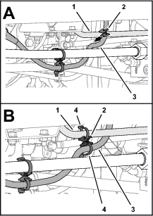
Secure the positive battery cable to the negative battery cable with the double-loop cable tie as shown.
-
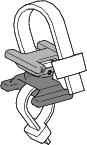
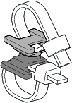
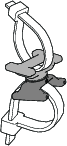
Rotate the halves of a swivel-saddle spacer 90° as shown in Figure 29.
-
Align a swivel-saddle spacer between the positive battery cable and the negative battery cable (Figure 30).
-
Secure the swivel-saddle spacer to the positive battery cable and negative battery cable with 2 cable ties (Figure 30).
-
Align the halves of a swivel-saddle spacer parallel as shown in Figure 31.
-
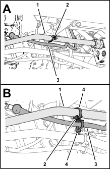
Align a swivel-saddle spacer between the positive battery cable and the tube that connects port T of the hydraulic manifold and the hydraulic tank (Figure 32).
-
Secure the swivel-saddle spacer to the tube and the positive battery cable with 2 cable ties (Figure 32).
-
Below the battery storage box, secure the positive and negative battery cable with a double loop-cable tie as shown in Figure 33.
-
Torque the nut securing the positive battery cable to the starter to 23 to 29 N∙m (17 to 21 ft-lb).
-
Slip the battery cable insulator over the terminal and nut of the starter.
Securing the Positive Battery Cable
Important: Ensure that the cable ties and swivel-saddle spacers secure the positive battery cable to the hydraulic tubes and negative battery cable.
-
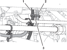
Align the halves of a swivel-saddle spacer parallel as shown in Figure 34.
-
Align a swivel-saddle spacer between the positive battery cable and the hydraulic-cooler tube from filter manifold port P1 (Figure 35).
-
Secure the swivel-saddle spacer to the tube and the positive battery cable with 2 cable ties (Figure 35).
-
Slightly rotate the halves of a swivel-saddle spacer as shown in Figure 36.
-
Align a swivel-saddle spacer between the positive battery cable and the front, right cutting-unit tube (Figure 37).
-
Secure the swivel-saddle spacer to the tube and the positive battery cable with 2 cable ties (Figure 37).
-
Below the battery storage box, secure the positive and negative battery cable with a double loop-cable tie as shown in Figure 38.
-
Torque the nut securing the positive battery cable to the starter to 23 to 29 N∙m (17 to 21 ft-lb).
-
Slip the battery cable insulator over the terminal and nut of the starter.
Assembling the Battery Cables to the Battery
Warning
Electrical sparks can cause the battery gasses to explode, resulting in personal injury.
Incorrect battery cable routing could damage the machine and cables, causing sparks.
-
Always disconnect the negative (black) battery cable before disconnecting the positive (red) cable.
-
Always connect the positive (red) battery cable before connecting the negative (black) cable.
-
Route the ring terminals and wires of the machine wire harness through the insulator of the positive battery cable (Figure 39).
-
Assemble the double ended battery-clamp stud and a nut onto the positive battery-cable clamp (Figure 39).
-
Assemble the ring terminals to the double ended battery-clamp stud and a nut, and tighten the nut (Figure 39).
-
Assemble the positive battery-cable clamp onto the positive post of the battery as shown in Figure 40, and tighten the nut and double ended battery-clamp stud.

-
Assemble the negative battery-cable clamp onto the negative post of the battery as shown in Figure 40, and tighten the nut and T-bolt.
-
Apply a thin coat of battery terminal protector to the positive and negative battery-cable clamps, posts, and hardware.
-
Slip the insulator over the battery-cable clamp.
Finishing Installing the Kit
-
Install the right, rear cutting unit to the lift arm.
-
Start the engine to verify machine operation.
-
Raise the cutting units.
-
Shut off the engine and remove the key.
-
Check that the positive and negative battery cables do not contact the cutting units or lift arms.
Important: If the either battery cable contact the cutting units or lift arms, check the routing if the battery cable and the location of the cable ties and swivel-saddle spacers; refer to the following procedures:
Groundsmaster 4500 and Groundsmaster 4700 Machines
Reelmaster 7000 Machines
-
Close the hood, and secure it with the 2 latches (Figure 41).
-
Close the cover of the battery storage box, and secure the cover with the latch (Figure 41).