Installation
Note: Determine the left and right sides of the machine from the normal operating position.
Preparing the Machine
-
Park the machine on a level surface.
-
Disengage the blade-control switch.
-
Move the motion-control levers outward to the NEUTRAL-LOCK position.
-
Engage the parking brake.
-
Shut off the engine and remove the key.
Installing the Handle Extension
Parts needed for this procedure:
| Handle extension | 2 |
| Flange-head bolt (3/8 x 1-3/4 inches) | 4 |
| Spacer | 2 |
| Locknut (3/8 inch) | 4 |
-
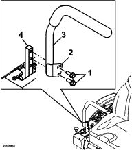
Remove the motion-control lever (Figure 1).
Retain the motion-control lever and 2 flange-head bolts (3/8 x 1 inch) for later installation.
-
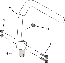
Loosely secure the handle extension to the motion-control lever using 2 flange-head bolts (3/8 x 1-3/4 inches), 1 spacer, and 2 locknuts (3/8 inch) as shown in Figure 2.
-
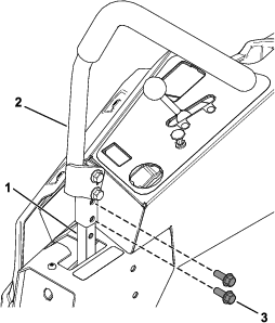
Secure the assembled motion-control lever to the control-arm shaft using the previously removed 2 flange-head bolts (3/8 x 1 inch) as shown in Figure 3.
Torque the 2 flange-head bolts (3/8 x 1 inch) to 41 N∙m (30 ft-lb).
-
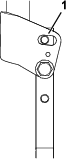
Move the motion-control lever forward or rearward to the desired position in the slotted hole (Figure 4).
-
Torque the 2 flange-head bolts (3/8 x 1-3/4 inches) to 41 N∙m (30 ft-lb).
-
Repeat the installation on the other side of the machine.