

Maintenance
Note: Determine the left and right sides of the machine from the normal operating position.
Maintenance Safety
-
Park machine on level ground. Set the parking brake, stop engine and remove key or disconnect spark plug wire. Wait for all moving parts to stop before leaving the operator’s position. Allow the machine to cool before servicing, adjusting, fueling, unclogging, cleaning, or storing.
Warning
The engine can become very hot. Touching a hot engine can cause severe burns.
Allow the engine to cool completely before service or making repairs around the engine area.
-
If you leave the key in the switch, someone could accidently start the engine and seriously injure you or other bystanders. Remove the key from the switch before you perform any maintenance.
-
Never allow untrained personnel to service machine.
-
Park machine on level ground, set parking brake, stop engine, and remove key. Wait for all moving parts to stop before leaving the operator’s position. Allow the machine to cool before servicing, adjusting, fueling, unclogging, cleaning, or storing.
-
Keep all guards, shields, switches, and all safety devices in place and in proper working condition. Frequently check for worn or deteriorating components and replace them with genuine Z Turf Equipment parts when necessary.
Warning
Removal or modification of original equipment, parts and/or accessories may alter the warranty, controllability, and safety of the machine. Unauthorized modifications to the original equipment or failure to use original Z Turf Equipment parts could lead to serious injury or death. Unauthorized changes to the machine, engine, fuel or venting system, may violate applicable safety standards such as: ANSI, OSHA and NFPA and/or government regulations such as EPA and CARB.
-
Keep your hands and feet away from moving parts or hot surfaces. If possible, Do Not make adjustments with the engine running.
Warning
Contact with moving parts or hot surfaces may cause personal injury.
Keep your fingers, hands, and clothing clear of rotating components and hot surfaces.
-
Keep all parts in good working condition and all hardware tightened.
Periodic Maintenance
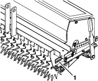
Check the Spiker Blades, Cutting Blades, and Bearings
| Maintenance Service Interval | Maintenance Procedure |
|---|---|
| Before each use or daily |
|
-
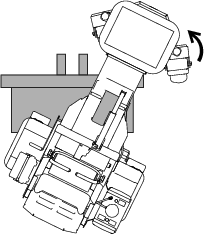
Raise the accessory.
-
Stop engine, wait for all moving parts to stop, and remove spark plug wire. Engage parking brake.
-
Inspect the blades for damage and wear and replace as required.
Danger
A worn or damaged blade can break. A piece of the blade could be thrown into the operator’s or bystander’s area, resulting in serious personal injury or death.
-
Inspect the blade periodically for wear or damage.
-
Replace a worn or damaged blade.
-
-
Spin the cutting blade assembly; it should spin freely. If it makes a grinding noise and/or halting, the bearings are worn; replace them when the blades are replaced.
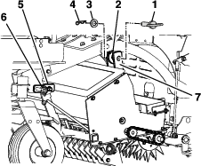
Check Condition Of Chains
| Maintenance Service Interval | Maintenance Procedure |
|---|---|
| Before each use or daily |
|
-
Raise the accessory.
-
Stop engine, wait for all moving parts to stop, and remove spark plug wire. Engage parking brake.
-
Check the chains for proper tension. The chains should be able to move up and down 1/4-1/2 inch (6-12 mm).
Check Condition Of Sprockets
| Maintenance Service Interval | Maintenance Procedure |
|---|---|
| Before each use or daily |
|
-
Stop engine, wait for all moving parts to stop, and remove key. Engage parking brake.
-
Inspect sprockets for wear and replace as required.
Lubricate Chains
| Maintenance Service Interval | Maintenance Procedure |
|---|---|
| Before each use or daily |
|
Important: Do Not lubricate chains with penetrating oil or solvents. Use oil or chain lubricant.
-
Stop engine, wait for all moving parts to stop, and remove key. Engage parking brake.
-
Slowly move the chain and lubricate.
-
Check the condition and tension of the chains (see Check Condition Of Chains section).
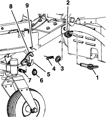
Lubricate Grease Fittings
| Maintenance Service Interval | Maintenance Procedure |
|---|---|
| Every 25 hours |
|
Note: See chart for service intervals.
-
Stop engine, wait for all moving parts to stop, and remove key. Engage parking brake.
-
Lubricate fittings with NLGI grade #2 multi-purpose gun grease.
Refer to the following chart for fitting locations and lubrication schedule.
Lubrication Chart
Fitting Locations Initial Pumps Number of Places Service Interval 1. Pillow Block Bearings 1 4 25 hours
Check for Loose Hardware
| Maintenance Service Interval | Maintenance Procedure |
|---|---|
| Before each use or daily |
|
-
Stop engine, wait for all moving parts to stop, and remove spark plug wire. Engage parking brake.
-
Visually inspect machine for any loose hardware or any other possible problem. Tighten hardware or correct the problem before operating.
Cleaning
Cleaning and Storing Safety
-
Park machine on level ground, disengage drives, set parking brake, stop engine, and remove key. Wait for all moving parts to stop before leaving the operator’s position. Allow the machine to cool before servicing, adjusting, fueling, unclogging, cleaning, or storing.
-
Clean grass and debris from the accessory, muffler, drives, and engine compartment to prevent fires.
-
Allow the machine to cool before storing the machine in any enclosure. Do Not store the machine or fuel container, or refuel, where there is an open flame, spark, or pilot light such as on a water heater or other appliance.
Clean Debris From Machine
| Maintenance Service Interval | Maintenance Procedure |
|---|---|
| Before each use or daily |
|
-
Stop engine, wait for all moving parts to stop, and remove key. Engage parking brake.
-
Clean off any oil, debris, or build-up on the machine, especially the accessory, around engine and exhaust area.
Important: You can wash the machine with mild detergent and water. Do not pressure wash the machine. Avoid excessive use of water, especially near the control panel, under the cushion, around the engine, hydraulic pumps, motors, and drive axle seals.