| Maintenance Service Interval | Maintenance Procedure |
|---|---|
| Before each use or daily |
|
Introduction
This machine is a ride-on, reel-blade lawn mower intended to be used by professional, hired operators in commercial applications. It is primarily designed for cutting grass on well-maintained turf. Using this product for purposes other than its intended use could prove dangerous to you and bystanders.
Read this information carefully to learn how to operate and maintain your product properly and to avoid injury and product damage. You are responsible for operating the product properly and safely.
Visit www.toro.com/en-gb for more information, including safety tips, training materials, accessory information, help finding a dealer, or to register your product.
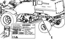
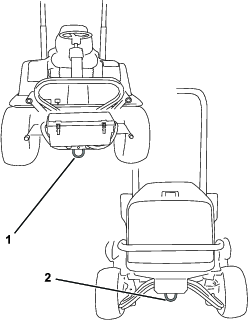
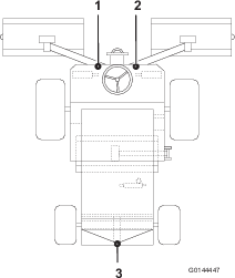
Whenever you need service, genuine Toro parts, or additional information, contact an Authorized Service Dealer or Toro Customer Service and have the model and serial numbers of your product ready. Figure 1 identifies the location of the model and serial numbers on the product. Write the numbers in the space provided.
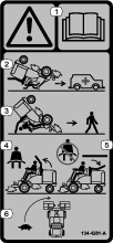
This manual identifies potential hazards and has safety messages identified by the safety-alert symbol (Figure 2), which signals a hazard that may cause serious injury or death if you do not follow the recommended precautions.

This manual uses 2 words to highlight information. Important calls attention to special mechanical information and Note emphasizes general information worthy of special attention.
This product complies with all relevant European directives; for details, please see the separate product specific Declaration of Conformity (DOC) sheet.
Safety
This machine has been designed in accordance with EN ISO 5395.
General Safety
This product is capable of amputating hands and feet and of throwing objects.
-
Read and understand the contents of this Operator’s Manual before starting the engine.
-
Use your full attention while operating the machine. Do not engage in any activity that causes distractions; otherwise, injury or property damage may occur.
-
Do not put your hands or feet near moving components of the machine.
-
Do not operate the machine without all guards and other safety protective devices in place and functioning properly on the machine.
-
Keep bystanders and children out of the operating area. Never allow children to operate the machine.
-
Shut off the engine, remove the key, and wait for all movement to stop before you leave the operator’s position. Allow the machine to cool before adjusting, servicing, cleaning, or storing it.
Improperly using or maintaining this machine can result in injury.
To reduce the potential for injury, comply with these safety instructions
and always pay attention to the safety-alert symbol  , which means
Caution, Warning, or Danger—personal safety instruction. Failure
to comply with these instructions may result in personal injury or
death.
, which means
Caution, Warning, or Danger—personal safety instruction. Failure
to comply with these instructions may result in personal injury or
death.
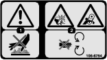
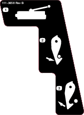
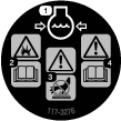
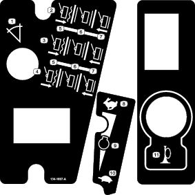
Safety and Instructional Decals
|
Safety decals and instructions are easily visible to the operator and are located near any area of potential danger. Replace any decal that is damaged or missing. |


Setup
Store all documentation in a safe place for future use.
Note: Determine the left and right sides of the machine from the normal operating position.
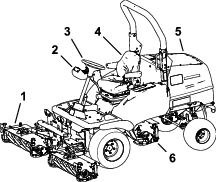
Product Overview
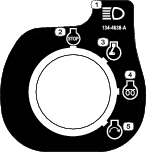
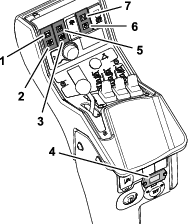
Control Console Controls
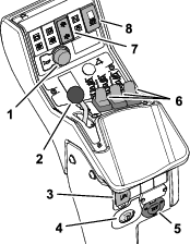
Audible Warning Horn
Important: The horn sounds when an engine coolant overheat condition occurs. Shut off the engine immediately, and repair the machine before starting the engine again.
Press the horn button to provide an audible warning (Figure 5).
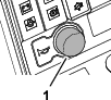
Throttle Control
-
To increase the engine speed, move the throttle-control lever (Figure 6) forward.
-
To decrease engine speed, move the throttle-control lever rearward.
Note: Engine speed influences the speed of the other functions, i.e. ground speed, reel speed and cutting unit lift rate.
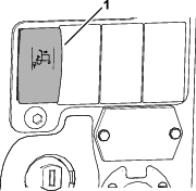
Auto Reverse Limited-Lift Switch
The auto reverse limited-lift switch controls whether cutting units can rise automatically to the limited lift position when driving the machine backward.
-
To enable auto reverse-limited lift, press the top of the auto reverse limited-lift switch (Figure 7).
The LED light in the switch illuminates when limited lift in reverse is enabled.
-
To shut off auto reverse-limited lift, press the bottom of the auto reverse limited-lift switch.
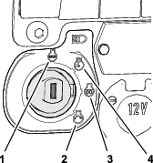
Ignition Key
Caution
If you leave the key in the ignition switch, someone could accidently start the engine and seriously injure you or bystanders.
Remove the key from the ignition.
The ignition switch has 4 positions to control the engine and machine electrical power.
Lift-Control Switches
Use the lift-control switches to raise and lower the cutting units (Figure 9).
Cutting-Unit Drive Switch
-
To run the cutting units, press the top of the cutting-unit drive switch (Figure 10).
The LED light in the switch illuminates when the cutting units are running.
-
To shut off the cutting units, press the bottom of the cutting-unit drive switch.
Important: Always shut off cutting units when you are not cutting.
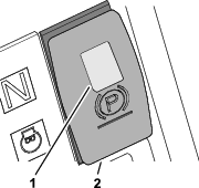
Parking Brake Switch
Important: Do not operate the mower with the parking brake engaged, and do not engage the parking brake while the mower is moving.
Important: The parking brake operates on the front wheels only. Do not park the mower on a slope.
To engage the parking brake, pressing the smaller (orange) locking button, and moving the brake switch forward (Figure 11).
Note: The LED light in the switch illuminates when the parking brake is engaged and the ignition key is turned to the RUN position.
Service Brake
The hydraulic transmission provides the machine with service-brake effect. When you release the forward or reverse travel pedals, or reduce engine speed the transmission produces service-brake effect and ground speed slows or stops the machine. To increase the transmission-braking effect, push the transmission pedal into the NEUTRAL position. Only the front wheels provide service brake effect.
Danger
The service braking system does not keep the machine from rolling when parked. The machine could move unintentionally.
Engage the parking brake when you park the machine.
Emergency Brake
If the service brake is damaged or ineffective, shut off the engine, engage the parking brake remove the key, and have the machine repaired.
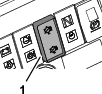
Control Console Indicators
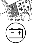
Low Battery Charge Warning Light
The battery charge warning light illuminates when low battery charge occurs (Figure 13).
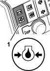
Low Engine-Oil Pressure Warning Light
The engine-oil pressure warning light illuminates when the oil pressure is too low (Figure 14).
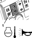
Engine Coolant Overheating Warning Light
The engine coolant warning light illuminates, the horn is actuated, and the cutting units stop (Figure 15).
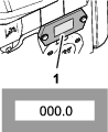
Hour Meter
The hour meter shows the total hours that the machine has been operated (Figure 16).
Transmission Neutral Indicator Light
The transmission neutral indicator light illuminates when the traction pedals are in the NEUTRAL position and the ignition key is turned to the RUN position (Figure 17).
Note: You must engage the parking brake for the transmission neutral indicator light to illuminate.
Engine Preheat Indicator Light
Turn the ignition key to position PREHEAT. The engine preheat indicator light illuminates and the glow plugs energize to help start a cold engine. (Figure 18).
Important: Attempting to start a cold engine before using the preheat may cause unnecessary battery wear.
Traction Pedals
Forward travel: Press the forward traction pedal to drive the machine forward and increase ground speed. Release the pedal to reduce ground speed (Figure 19).
Reverse travel: Press the reverse traction pedal to drive the machine backward and increase ground speed. Release the pedal to reduce ground speed (Figure 19).
Stop (Neutral): To stop the machine, use 1 of the following procedures:
-
Reduce your foot pressure on the traction pedal and allow it to return to the neutral position. The machine dynamically brakes to a smooth stop.
-
Tap or hold the opposite pedal briefly—this stops the machine faster than dynamic braking.
Adjustable Steering Column
Adjust the steering wheel and column only when the machine is parked on level ground.
-
To tilt the steering wheel, press the foot pedal down.
-
Position the steering tower to the most comfortable position and release the pedal (Figure 20).

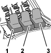
Operator’s Seat Controls
Forward/Backward Adjustment
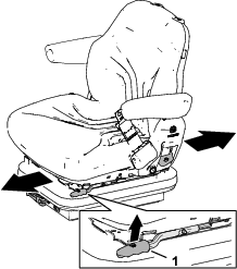
Move the lever upward to adjust the forward/backward position of the seat. Release the lever to lock the seat in position (Figure 21).
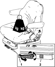
Operator Weight Adjustment
Rotate the handle clockwise to increase suspension stiffness and counterclockwise to decrease the stiffness. The dial indicates when the seat suspension is adjusted for the operator’s weight (kg); refer to Figure 22.
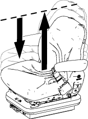
Height Adjustment
To adjust seat height incremental, manually lift the seat. To lower the seat, lift it beyond the highest setting, allow it to drop to the lowest setting, and if needed manually lift the seat to the desired height (Figure 23).
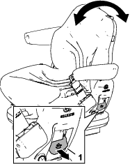
Backrest Adjustment
Pull the handle outward to adjust the seat backrest angle. Release the handle to lock the seat backrest in position (Figure 24).
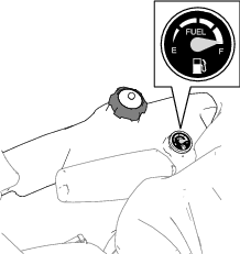
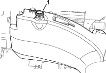
Fuel Gauge
The fuel gauge shows the amount of fuel in the tank (Figure 25).
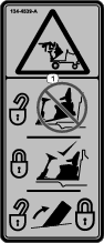
Transport Latches
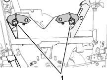
Front Cutting Unit Arm Latches
Raise the cutting units to the TRANSPORT position and secure the arm-latch pins to the latches with the bails (Figure 26).
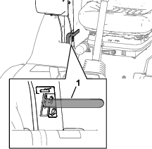
Rear Cutting Unit Arm Latch
Raise the cutting units to the TRANSPORT position, push down the latch handle for the rear cutting-unit arm, and move the handle forward and up (Figure 27).
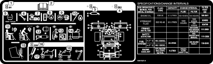
Note: Specifications and design are subject to change without notice.
|
Transport Width |
138 cm (54-5/16 inches) |
|
Width of Cut |
212 cm (83-1/2 inches) |
|
Overall Width (heads down) |
231 cm (91 inches) |
|
Length |
286 cm (112-5/8 inches) |
|
Height |
160.5 cm (63-3/16 inches) with ROPS folded |
|
211.5 cm (83-5/16 inches) with ROPS in the vertical operating position |
|
|
Weight |
1270 kg (2800 lb) |
|
(with full fluids and 200 mm 6-blade cutting units) |
|
|
Engine |
Kubota 18.5 kw (25 hp) at 3000 rpm DIN 70020 |
|
Fuel-Tank Capacity |
45 L (11.9 US gallons) |
|
Transport Speed |
22 km/h (13.7 mph) |
|
Mowing Speed |
11 km/h (6.8 mph) |
|
Hydraulic-System Capacity |
32 L (8.5 US gallons) |
Attachments/Accessories
A selection of Toro approved attachments and accessories is available for use with the machine to enhance and expand its capabilities. Contact your Authorized Service Dealer or authorized Toro distributor or go to www.toro.com/en-gb for a list of all approved attachments and accessories.
To ensure optimum performance and continued safety certification of the machine, use only genuine Toro replacement parts and accessories. Replacement parts and accessories made by other manufacturers could be dangerous, and such use could void the product warranty.
Operation
Before Operation
Before Operation Safety
General Safety
-
Never allow children or untrained people to operate or service the machine. Local regulations may restrict the age of the operator. The owner is responsible for training all operators and mechanics.
-
Become familiar with the safe operation of the equipment, operator controls, and safety signs.
-
Before you leave the operator’s position, do the following:
-
Park the machine on a level surface.
-
Disengage and lower the cutting units.
-
Engage the parking brake.
-
Shut off the engine and remove the key.
-
Wait for all movement to stop.
-
Allow the machine to cool before adjusting, servicing, cleaning, or storing it.
-
-
Know how to stop the machine and shut off the engine quickly.
-
Do not operate the machine without all guards and other safety protective devices in place and functioning properly on the machine.
-
Before mowing, always inspect the machine to ensure that the cutting units are in good working condition.
-
Inspect the area where you will use the machine and remove all objects that the machine could throw.
Fuel Safety
-
Use extreme care in handling fuel. It is flammable and its vapors are explosive.
-
Extinguish all cigarettes, cigars, pipes, and other sources of ignition.
-
Use only an approved fuel container.
-
Do not remove the fuel cap or fill the fuel tank while the engine is running or hot.
-
Do not add or drain fuel in an enclosed space.
-
Do not store the machine or fuel container where there is an open flame, spark, or pilot light, such as on a water heater or other appliance.
-
If you spill fuel, do not attempt to start the engine; avoid creating any source of ignition until the fuel vapors have dissipated.
Performing Daily Maintenance
Before starting the machine each day, perform the Each Use/Daily procedures listed in .
Filling the Fuel Tank
Fuel Tank Capacity
45 L (11.9 US gallons)
Fuel Specification
Note: We recommend that you use only ultra-low sulphur diesel fuel.
-
Never use kerosene or gasoline instead of diesel fuel.
-
Never mix kerosene or used engine oil with the diesel fuel.
-
Never keep fuel in containers with zinc plating on the inside.
-
Do not use fuel additives.
Petroleum Diesel
Cetane rating: 45 or higher
Sulfur content: Ultra-low sulfur (<15 ppm)
| Diesel fuel specification | Location |
| ASTM D975 | USA |
| No. 1-D S15 | |
| No. 2-D S15 | |
| EN 590 | European Union |
| ISO 8217 DMX | International |
| JIS K2204 Grade No. 2 | Japan |
| KSM-2610 | Korea |
-
Use only clean, fresh diesel fuel or biodiesel fuels.
-
Purchase fuel in quantities that you can use within 180 days to ensure fuel freshness.
Use summer-grade diesel fuel (No. 2-D) at temperatures above -7°C (20°F) and winter-grade fuel (No. 1-D or No. 1-D/2-D blend) below that temperature.
Note: Use of winter-grade fuel at lower temperatures provides lower flash point and cold flow characteristics which eases starting and reduces fuel filter plugging.Using summer-grade fuel above -7°C (20°F) contributes toward longer fuel pump life and increased power compared to winter-grade fuel.
Biodiesel
This machine can also use a biodiesel blended fuel of up to B20 (20% biodiesel, 80% petroleum diesel).
Sulfur content: Ultra-low sulfur (<15 ppm)
Biodiesel fuel specification: ASTM D6751 or EN14214
Blended fuel specification: ASTM D975, EN590, or JIS K2204
Important: The petroleum diesel portion must be ultra-low sulfur.
Observe the following precautions:
-
Biodiesel blends may damage painted surfaces.
-
Use B5 (biodiesel content of 5%) or lesser blends in cold weather.
-
Monitor seals, hoses, gaskets in contact with fuel as they may degrade over time.
-
You may expect a plugged fuel filter plugging for a period after converting to biodiesel blends.
-
Contact your authorized Toro distributor for more information on biodiesel.
Adding Fuel
-
Park the machine on a level surface, lower the cutting units, shut off the engine, engage the parking brake, and remove the key.
-
Using a clean rag, clean area around fuel-tank cap.
-
Remove the cap from the fuel tank (Figure 28).
-
Fill the tank until the level is 25 mm (1 inch) below the bottom of the filler neck.
-
Install the fuel-tank cap tightly after filling the tank.
Note: If possible, fill the fuel tank after each use. This minimizes possible buildup of condensation inside the fuel tank.
Understanding the Operator-Presence Controls
| Maintenance Service Interval | Maintenance Procedure |
|---|---|
| Before each use or daily |
|
Warning
Operating the machine when the operator presence controls are malfunctioning could result in personal injury.
Do not operate the turf mower if the operator presence controls are malfunctioning in any way. Always replace damaged or worn parts and check that they function correctly before operating the machine.
Caution
If safety interlock switches are disconnected or damaged, the machine could operate unexpectedly, causing personal injury.
-
Do not tamper with the interlock switches.
-
Check the operation of the interlock switches daily and replace any damaged switches before operating the machine.
Engine Start Interlock
To start the engine, you must preform the following actions:
-
Engage the parking brake.
-
Ensure that the traction pedals are in the NEUTRAL position.
-
Ensure that the cutting unit drive switch is in the OFF position.
Engine Run Interlock
Note: The engine shuts off if you leave the seat without engaging the parking brake.
While the engine is running, you must stay seated whenever the parking brake is disengaged, otherwise the engine shuts off.
Cutting Unit Drive Interlock
You must remain seated to run the cutting units. If you rise from the seat for 1 second or longer, the cutting units disengage. To run the cutting units again, you must sit in the seat, then cycle the cutting unit drive switch to the OFF position and to the ON position.
Note: If you momentarily rise off the seat during normal work, the cutting units continue running.
During Operation
General Safety
-
The owner/operator can prevent and is responsible for accidents that may cause personal injury or property damage.
-
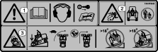
Wear appropriate clothing, including eye protection; long trousers; substantial, slip-resistant footwear; and hearing protection. Tie back long hair and do not wear loose clothing or loose jewelry.
-
Do not operate the machine while ill, tired, or under the influence of alcohol or drugs.
-
Use your full attention while operating the machine. Do not engage in any activity that causes distractions; otherwise, injury or property damage may occur.
-
Before you start the engine, ensure that all drives are in neutral, the parking brake is engaged, and you are in the operating position.
-
Do not carry passengers on the machine and keep bystanders and children out of the operating area.
-
Operate the machine only in good visibility to avoid holes or hidden hazards.
-
Avoid mowing on wet grass. Reduced traction could cause the machine to slide.
-
Keep your hands and feet away from the cutting units.
-
Look behind and down before backing up to be sure of a clear path.
-
Use care when approaching blind corners, shrubs, trees, or other objects that may obscure your vision.
-
Stop the cutting units whenever you are not mowing.
-
Slow down and use caution when making turns and crossing roads and sidewalks with the machine. Always yield the right-of-way.
-
Operate the engine only in well-ventilated areas. Exhaust gases contain carbon monoxide, which is lethal if inhaled.
-
Do not leave a running machine unattended.
-
Before you leave the operator’s position, do the following:
-
Park the machine on a level surface.
-
Disengage and lower the cutting units.
-
Engage the parking brake.
-
Shut off the engine and remove the key.
-
Wait for all movement to stop.
-
Allow the machine to cool before adjusting, servicing, cleaning, or storing it.
-
-
Operate the machine only in good visibility and appropriate weather conditions. Do not operate the machine when there is the risk of lightning.
Rollover Protection System (ROPS) Safety
-
Do not remove any of the ROPS components from the machine.
-
Ensure that the seat belt is attached and that you can release it quickly in an emergency.
-
Always wear your seat belt.
-
Check carefully for overhead obstructions and do not contact them.
-
Keep the ROPS in safe operating condition by thoroughly inspecting it periodically for damage and keeping all the mounting fasteners tight.
-
Replace all damaged ROPS components. Do not repair or alter them.
Machines with a Foldable Roll Bar
-
Always use the seat belt with the roll bar in the raised position.
-
The ROPS is an integral safety device. Keep a folding roll bar in the raised and locked position, and use the seat belt when operating the machine with the roll bar in the raised position.
-
Lower a folding roll bar temporarily only when necessary. Do not wear the seat belt when the roll bar is folded down.
-
Be aware that there is no rollover protection when a folded roll bar is in the down position.
-
Check the area that you will be mowing and never fold down a folding roll bar in areas where there are slopes, drop-offs, or water.
Slope Safety
-
Slopes are a major factor related to loss of control and rollover accidents, which can result in severe injury or death. You are responsible for safe slope operation. Operating the machine on any slope requires extra caution.
-
Evaluate the site conditions to determine if the slope is safe for machine operation, including surveying the site. Always use common sense and good judgment when performing this survey.
-
Review the slope instructions, listed below, for operating the machine on slopes. Before you operate the machine, review the site conditions to determine whether you can operate the machine in the conditions on that day and at that site. Changes in the terrain can result in a change in slope operation for the machine.
-
Avoid starting, stopping, or turning the machine on slopes. Avoid making sudden changes in speed or direction. Make turns slowly and gradually.
-
Do not operate a machine under any conditions where traction, steering, or stability is in question.
-
Remove or mark obstructions such as ditches, holes, ruts, bumps, rocks, or other hidden hazards. Tall grass can hide obstructions. Uneven terrain could overturn the machine.
-
Be aware that operating the machine on wet grass, across slopes, or downhill may cause the machine to lose traction.
-
Use extreme caution when operating the machine near drop-offs, ditches, embankments, water hazards, or other hazards. The machine could suddenly roll over if a wheel goes over the edge or the edge caves in. Establish a safety area between the machine and any hazard.
-
Identify hazards at the base of the slope. If there are hazards, mow the slope with a pedestrian-controlled machine.
-
If possible, keep the cutting units lowered to the ground while operating on slopes. Raising the cutting units while operating on slopes can cause the machine to become unstable.
-
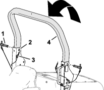
Lowering the Roll Bar
-
Park the machine on a level surface, lower the cutting units, engage the parking brake, shut off the engine, and remove the key.
-
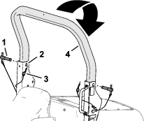
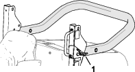
Remove the hairpins from the roll-bar pins in the pivot brackets of the lower roll-bar frame (Figure 29).
-
While supporting the weight of the upper roll bar, remove the roll-bar pins from the pivot brackets (Figure 29).
-
Carefully lower the upper roll bar until it rests on the stops of the lower roll-bar frame.
-
Insert the roll-bar pins in the lower holes of the pivot brackets (Figure 30).
-
Secure roll-bar pins to the pivot brackets with the hairpins.
Raising the Roll Bar
-
Remove the hairpins that secure the roll-bar pins to the pivot brackets of the lower roll-bar frame.
-
Remove the roll-bar pins from the pivot brackets (Figure 31).
-
Raise the upper roll bar until the holes in the roll bar align with the pivot brackets (Figure 32).
-
Insert the roll-bar pins through the upper holes of the pivot brackets and the upper roll bar (Figure 32).
-
Secure roll-bar pins to the pivot brackets with the hairpins (Figure 32).
Starting and Shutting Off the Engine
Important: If you are starting the engine for the first time, the engine has shut off due to lack of fuel, or you have performed maintenance on the fuel system—you must bleed the fuel system before starting the engine; refer to Bleeding the Fuel System.
Warning
Operating the machine in an unsafe manner could result in personal injury.
Before starting the engine, ensure that the following conditions are met:
-
The area is clear of bystanders.
-
The cutting unit drive is disengaged.
-
The parking brake is engaged.
-
The traction pedals are in the neutral position.
Important: This machine is fitted with an engine start lockout; refer to Understanding the Operator-Presence Controls.
Starting the Engine
-
Sit on the seat, keep your foot off the traction pedals so that they return to the NEUTRAL position, engage the parking brake, and set the throttle to the 70% throttle position.
-
Turn the ignition key to the RUN position (Figure 33).
Note: The engine-oil pressure and battery charge warning lights illuminate.
-
If the engine is cold, turn the ignition key to the PREHEAT position, and hold the key for 5 seconds.
Note: The glow plug energizes and the pre-heat indicator light illuminates.
-
Turn the key to the start position, crank the engine to start it, and release the key.
Important: Do not crank the engine longer than 15 seconds.
-
If the engine is cold, run it at idle speed until it warms.
Warning
An illuminated warning light could indicate a serious problem that could lead to personal injury.
When the engine is operating normally, all warning lights should shut off. If a warning light illuminates, shut off the engine immediately and repair the machine before starting the engine.
Shutting off the Engine
-
Keep your foot off the traction pedals so that they return to the NEUTRAL position, engage the parking brake, and lower the cutting units.
-
Move the throttle to the idle position, and allow the engine to idle for 5 minutes.
-
Turn the ignition key to the STOP position.
If the engine fails to shut off when the ignition key is turned to the STOP position, operate the engine shutoff lever in the forward direction (Figure 34).
Warning
Contact with hot or moving parts can result in personal injury.
Keep all body parts away from any hot or moving parts of the engine.
Using the Cutting Units
Adjusting the Grass Deflectors
Adjust the rear grass deflectors as low as possible so that grass clippings discharge to the ground without restricting clippings exiting cutting unit (Figure 35).
Note: Always position the rear grass deflectors correctly.
Adjusting the Center Cutting Unit Height-of-Cut Correction
With all cutting units set at the same HOC as shown by the indicator rings, the center cutting unit may produce a higher cut finish compared to that of the left and right cutting units. The machine pulls the center cutting unit but pushes the left and right cutting units; this affects the cutting unit angle relative to the ground. The amount of HOC variation that results from this effect is also influenced by the terrain, but you can achieve satisfactory results by setting the center cutting unit HOC indicator ring lower than the left and right cutting unit settings.
Controlling the Position of the Individual Cutting Units
Use the 3 lift-control switches to raise or lower the cutting units independently.
Lowering the Cutting Unit
-
Press the cutting-unit-drive switch to the FORWARD ROTATION position.
-
Press the lift-control switch forward and release.
Note: The cutting unit engages when it is approximately 150 mm (6 inches) above ground level. The cutting unit is in ‘float’ mode, and follows the ground contours.
Note: The lift-control switch automatically returns to the (NEUTRAL) position when you release it.
Raising the Cutting Unit
-
Pull and hold the lift-control switch.
-
Release the lift-control switches when the cutting units are at the needed height.
Note: The lift-control switches automatically return to the (NEUTRAL) position when you release it and the cutting unit arms hydraulically lock into position.
Raising the Cutting Units
Auto-Limited Lift
When the cutting unit drive switch is in the ON position and the cutting units lowered, momentarily move the 3 lift-control switches (Figure 37) rearward.
Note: The cutting units shut off immediately and raise to approximately 150 mm (6 inches) above ground level.
Auto-Limited Lift in Reverse
With auto-limited lift in reverse engaged, driving the machine in reverse causes the cutting units to automatically raise to the limited-lift position.
Important: The cutting units continue to run while driving in reverse with the auto-limited lift in reverse engaged.
Operating the Machine with the Auto-Limited Lift in Reverse Engaged
-
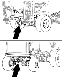
Press the auto-limited lift in reverse switch to the ON position (Figure 38).
-
With cutting units lowered and running, drive the machine in the reverse direction.
Note: The cutting units automatically raise to approximately 150 mm (6 inches) above ground level.
-
Drive the machine in the forward direction.
Note: The cutting units lower and return to the floating position.
-
To shut off auto-limited lift in reverse, press the auto-limited lift in reverse switch to the OFF position (Figure 38).
Cutting Unit Drive
The cutting unit drive engages only when you sit in the operator’s seat; refer toUnderstanding the Operator-Presence Controls.
Engaging the Cutting Unit Drive for Forward Rotation
Press the top of the cutting unit drive switch to the forward rotation position (Figure 39).
Engaging the Cutting Unit Drive for Reverse Rotation
Press the bottom of the cutting unit drive switch to the reverse rotation position (Figure 39).
Disengaging All Cutting Unit Drives
Press the cutting unit drive switch to the middle position (Figure 39).
Lowering the Cutting Units
Press the cutting unit drive switch to the forward rotation position. Press the lift-control switch(s) to the LOWER position. The cutting units run when they are approximately 150 mm (6 inches) above ground level.
Adjusting the Weight Transfer/Traction Assistance
A variable hydraulic weight transfer system provides improved tire grip with the grass surface—traction assistance.
Hydraulic pressure from the cutting-unit lift system provides a lifting force that reduces the weight of the cutting units on the ground and transfers the weight downward to the tires. This action is known as weight transfer.
Note: Adjust the amount of weight transfer to suit operating conditions.
-
Park the machine on a level surface, engage the parking brake, lower the cutting units to the ground, and wait for all moving parts to stop.
-
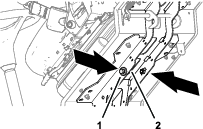
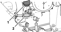
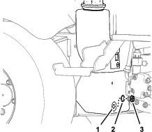
At the left side of the machine below the storage compartment, loosen the lock wheel of the weight transfer manifold 1/2 turn counterclockwise while holding the hand wheel steady (Figure 40).
-
Rotate the weight transfer hand wheel (Figure 40) as follows:
-
counterclockwise to reduce weight transfer
-
clockwise to increase weight transfer
Note: The recommended setting for the weight transfer/traction assistance is to increase the weight transfer until the cutting units start to lift, then rotate the hand wheel 1/2 turn counterclockwise.
-
-
Tighten the lock wheel (Figure 40).
Clearing the Cutting Units
Warning
Never attempt to rotate the cutting units by hand. Residual pressure in the hydraulic system could cause the cutting unit(s) to rotate suddenly when you release the blockage, which may cause serious injury.
-
Always wear protective gloves and use a suitable strong wooden instrument.
-
Ensure that the wooden instrument fits between the blades and through the reel and is long enough to provide leverage to release the blockage.
-
Park the machine on a level surface.
-
Move the traction pedal to the NEUTRAL position, engage the parking brake, and shut off the cutting units.
-
Lower the cutting units to the ground or securely lock them in the transport positions.
-
Shut off the engine, remove the key, and wait for all moving parts to stop.
-
Release all stored energy devices.
-
Check that all moving parts are stationary.
-
Using a suitable strong wooden instrument, remove the blockage. Ensure that the wooden instrument is properly supported in the cutting unit and avoid using excessive force to prevent damage.
-
Remove the wooden instrument from the cutting unit before starting the engine.
-
Repair or adjust the cutting unit if required.
Operating Tips
Becoming Familiar with the Machine
Before mowing grass, practice operating the machine in an open area. Start and shut off the engine. Operate in forward and reverse. Lower and raise the cutting unit, and engage and disengage them. When you feel familiar with the machine, practice operating it up and down slopes.
Understanding the Warning System
If a warning light comes on during operation, stop the machine immediately and correct the problem before continuing operation. Serious damage could occur if you operate the machine with a malfunction.
Mowing Grass
To maintain the high quality of cut, keep the rotational speed of the cutting units as high as possible. This requires high engine speed.
Cutting performance is best when cutting against the lie of the grass. To take advantage of this effect, alternate the mowing direction between cuts.
Take care to not leave uncut strips of grass at the overlap at points between adjacent cutting units by avoiding tight turns.
Maximizing the Quality of Cut
The quality of cut deteriorates when the forward speed is too fast. Always balance the quality of cut with the required cutting rate, and set the forward speed accordingly.
Maximizing Engine Efficiency
Do not let the engine labor. If you notice that the engine starts to labor, reduce the forward speed or increase the height of cut. Ensure that the cutting unit blades are sharp.
Driving the Machine in Transport Mode
Important: Take care when driving the machine over obstacles such as roadside curbs.Always travel at slow speed over obstacles to prevent damage to the tires, wheels, and steering system. Ensure that the tires are inflated to the recommended pressures.
Always disengage the cutting unit drive when driving the machine across areas with no grass. Grass lubricates the cutting edges while mowing. Excessive heat builds if the cutting units are run when not mowing, resulting in rapid wear. For this reason, reduce cutting speed when mowing lightly grassed areas or when the grass is dry. Be careful when driving between objects so that you do not accidentally damage the machine or the cutting units.
Using the Rear Roller Scrapers
For optimum grass discharge, remove the rear roller scrapers where conditions allow.
If mud and grass start to build up on the rollers, install the scrapers. When installing the scraper wires, tension them correctly.
After Operation
General Safety
-
Park the machine on a level surface.
-
Disengage and lower the cutting units.
-
Engage the parking brake.
-
Shut off the engine and remove the key.
-
Wait for all movement to stop.
-
Allow the machine to cool before adjusting, servicing, cleaning, or storing it.
-
Clean grass and debris from the cutting units, drives, mufflers, cooling screens, and engine compartment to help prevent fires. Clean up oil or fuel spills.
-
Disengage the drive to the attachment whenever you are hauling or not using the machine.
-
Maintain and clean the seat belt(s) as necessary.
-
Do not store the machine or fuel container where there is an open flame, spark, or pilot light, such as on a water heater or on other appliances.
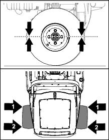
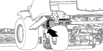
Identifying the Tie-Down Points
Hauling the Machine
-
Use full-width ramps for loading the machine onto a trailer or truck.
-
Tie the machine down securely.
Towing the Machine
Ensure that the towing vehicle can control the combined weight of both vehicles; refer to Specifications.
Raising the Cutting Units
Whenever possible, raise and latch the cutting units before towing the machine.
Releasing the Wheel-Motor Brakes
-
Engage the parking brake and chock the wheels of the towing vehicle.
-
Chock the front wheels of the machine.
-
Raise the platform forward; refer to Raising the Platform.
-
Remove the 2 bolts (12 x 40 mm) and 2 washers (12 mm) stored in the platform support rails (Figure 42).
-
Connect a rigid tow bar between the front tow ring of the machine and the tow vehicle (Figure 43).
-
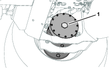
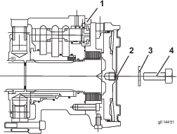
At the right, front wheel motor brake assembly remove the hex plug (Figure 44).
-
Assemble a bolt (12 x 40 mm) and washer (12 mm) into the hole at the center of the motor end plate (Figure 45).
-
Tighten the bolt in the threaded hole in the brake piston until the brake releases(Figure 45).
-
Repeat steps 6 through 8 for the brake at the left side of the machine.
Bypassing the Transmission Pump
-
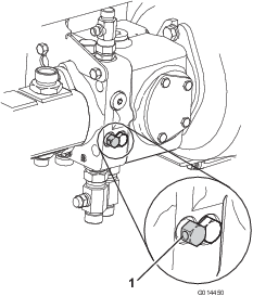
Decommission the hydraulic service braking system by turning the bypass valve (located under the transmission pump) counterclockwise (Figure 46), a maximum of 3 turns.
The mower is now in a freewheel condition and can be towed for a short distance at slow speed.
Important: You must manually steer the machine while it is towed. When the engine is shut off, there is no hydraulic steering assist—steering the machine feels heavy.
-
Lower and latch the platform; refer to Lowering the Platform.
-
Remove the wheel chocks.
Towing the Machine
Important: Do not tow the machine faster than 3 to 5 km/h (2 to 3 mph) and for no longer than 3 minutes; otherwise, internal damage to the transmission may occur.
-
Use the front tow ring to tow the machine.
-
Tow the machine a short distance, at slow speed, for no longer than 3 minutes.
Restoring the Transmission Pump
-
Chock the front wheels.
-
Raise the platform forward; refer to Raising the Platform.
-
Close the bypass valve on the transmission pump (Figure 47) by turning it clockwise.
Restoring the Brakes
-
Remove the bolt (12 x 40 mm) and washer (12 mm) from the hole at the center of the motor end plate (Figure 48).
-
Install the hex plug into the motor end plate (Figure 49).
-
Repeat steps 1 through 2 for the brake at the other side of the machine.
-
Remove the wheel chocks.
-
Disconnect the tow bar.
Note: The transmission and brakes are ready for operation.
-
Stow the 2 bolts (12 x 40 mm) and 2 washers (12 mm) stored in the platform support rails (Figure 49).
-
Lower the platform; refer to Lowering the Platform.
-
Disconnect the tow vehicle.
-
Check the brake operation of the machine.
Warning
Operating the machine without the braking system working properly may cause you to lose control of the machine, resulting in serious injury to you and bystanders.
Before using the machine, ensure that the braking system operates correctly. Carry out initial checks driving the machine at slow speed. Do not operate the machine with a damaged or disconnected braking system.
Maintenance
Note: Determine the left and right sides of the machine from the normal operating position.
Note: To obtain an electrical schematic or a hydraulic schematic for your machine, visit www.toro.com/en-gb.
Maintenance Safety
-
Before you leave the operator’s position, do the following:
-
Park the machine on a level surface.
-
Disengage and lower the cutting units.
-
Engage the parking brake.
-
Shut off the engine and remove the key.
-
Wait for all movement to stop.
-
Allow the machine to cool before adjusting, servicing, cleaning, or storing it.
-
-
Allow machine components to cool before performing maintenance.
-
If possible, do not perform maintenance while the engine is running. Keep away from moving parts.
-
Support the machine with jack stands whenever you work under the machine.
-
Carefully release pressure from components with stored energy.
-
Keep all parts of the machine in good working condition and all hardware tightened.
-
Replace all worn or damaged decals.
-
To ensure safe, optimal performance of the machine, use only genuine Toro replacement parts. Replacement parts made by other manufacturers could be dangerous, and such use could void the product warranty.
Recommended Maintenance Schedule(s)
| Maintenance Service Interval | Maintenance Procedure |
|---|---|
| After the first hour |
|
| After the first 10 hours |
|
| After the first 50 hours |
|
| Before each use or daily |
|
| Every 50 hours |
|
| Every 100 hours |
|
| Every 150 hours |
|
| Every 250 hours |
|
| Every 400 hours |
|
| Every 500 hours |
|
| Every 1,000 hours |
|
| Every 2 years |
|
Pre-Maintenance Procedures
Preparing the Machine for Maintenance
-
Park the machine on a level surface.
-
Engage the parking brake.
-
Lower the cutting units.
-
Shut off the engine and remove the key.
-
Wait for all movement to stop.
-
Allow the machine to cool before adjusting, servicing, or cleaning it.
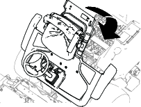
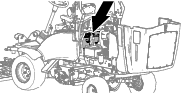
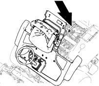
Raising the Platform
Lowering the Platform
Warning
Operating the machine with the platform unlatched may cause you to lose control of the machine, resulting in serious injury to you and bystanders.
Never operate the machine without first checking that the operator platform latching mechanism is fully engaged and in good working order.
-
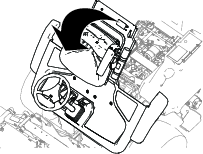
Lower the platform carefully (Figure 53).
Note: The gas lift cylinder helps support the platform.
-
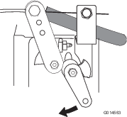
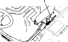
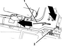
As the platform nears the fully lowered position, move the platform-latch handle (Figure 54) toward the front of the machine.
Note: This ensures that the latch hooks clear the locking bar.
-
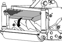
Fully lower the platform and move the platform-latch handle toward the rear of the machine until the latch hooks fully engage the locking bar (Figure 55).
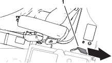
Removing the Storage Compartment
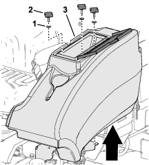
Installing the Storage Compartment
-
Align the holes on the bottom of the storage compartment with the holes in the chassis brackets.
-
Assemble the storage compartment to the machine with the 3 knobs and 3 washers (Figure 57)
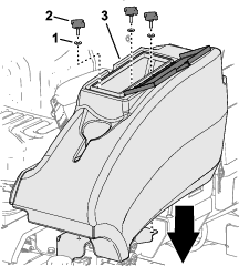
-
Close the storage-compartment door.
Locating the Lift Points
Note: Use jack stands to support the machine when you lift it.
Warning
Mechanical or hydraulic jacks may fail to support the machine and cause serious injury.
Use jack stands when supporting the machine.
-
Front—under the front arm mount
-
Rear—axle tube on the rear axle
Raising the Mower off the Ground
Warning
If you go under the machine while the engine is running, you could be seriously injured or killed.
-
Never crawl under the machine while the engine is running.
-
Never start the engine while someone is under the machine.
Important: Before raising the mower ensure that the lifting equipment is in good condition, and capable of supporting the weight of the machine securely.Minimum lift capacity: 2,000 kg (4,409 lb)
-
Park the machine on a level surface.
-
Engage the parking brake.
-
Shut off the engine and remove the ignition key.
-
Ensure that the ground under the lifting device is level and firm.
-
Align and ensure the lifting equipment is secure against one of the lifting points on the machine; refer to Locating the Lift Points.
-
If raising the front of the machine, chock the rear wheels to prevent the machine from rolling away.
Note: The parking brake operates only on the front wheels.
-
Support the machine with jack stands.
Lubrication
Greasing the Bearings, Bushings, and Pivots
| Maintenance Service Interval | Maintenance Procedure |
|---|---|
| Before each use or daily |
|
| Every 50 hours |
|
Important: Lubricate the bearings, bushings, and pivot points immediately after every washing, regardless of the service interval listed.
Grease specification: No. 2 lithium grease.
-
Prepare the machine for maintenance; refer to Preparing the Machine for Maintenance.
-
Use 1 pump of grease on the height-of-cut adjusters and 3 pumps of grease on all other grease fittings.
-
Refer to Figure 59 for the grease fitting locations.
-
Replace any damaged grease fittings.
-
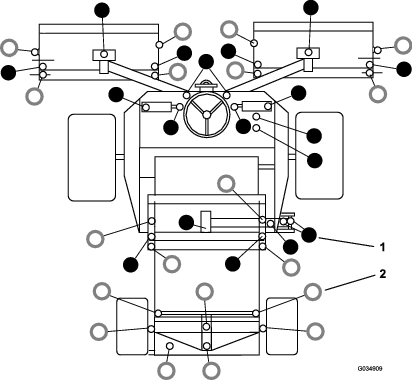
Figure 59
-
 Grease
every 50 hours
Grease
every 50 hours -
 Grease
daily
Grease
daily
Engine Maintenance
Engine Safety
-
Shut off the engine before checking the oil or adding oil to the crankcase.
-
Do not change the governor speed or overspeed the engine.
Checking the Engine Overheat Warning System
| Maintenance Service Interval | Maintenance Procedure |
|---|---|
| Every 100 hours |
|
-
Prepare the machine for maintenance; refer to Preparing the Machine for Maintenance.
-
Unlatch and open the hood.
-
Turn the ignition key to the ignition RUN position.
Note: Do not start the engine.
-
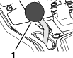
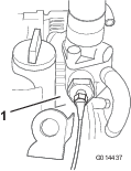
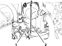
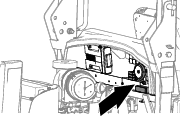
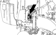
At the left side of the engine, disconnect the red/blue wire terminal from the engine temperature switch (Figure 60).
-
Touch the metal terminal of this wire onto a suitable earth point, ensuring that the metal surfaces make good contact.
Note: The horn sounds and the engine coolant temperature warning light illuminates to confirm operation.
Important: If the system is malfunctioning, make repairs before operating the mower.
-
Turn the ignition key to the ignition STOP position, and remove the key.
-
Close and latch the hood.
Checking the Air Filter-Blockage Indicator
| Maintenance Service Interval | Maintenance Procedure |
|---|---|
| Before each use or daily |
|
-
Prepare the machine for maintenance; refer to Preparing the Machine for Maintenance.
-
Unlatch and open the hood.
-
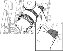
Check the air filter-blockage indicator (Figure 61).
Important: If the indicator is red, inspect the primary air filter and replace it if it is dirty or damaged; refer to Replacing the Primary Air Filter.
-
If the filter-blockage indicator is not red, close the hood.
-
Close and latch the hood.
Replacing the Primary Air Filter
| Maintenance Service Interval | Maintenance Procedure |
|---|---|
| Every 500 hours |
|
Check the air-cleaner body for damage that could cause an air leak. Replace the air-cleaner body if damaged. Check the whole intake system for leaks, damage, or loose hose clamps.
Note: Service the primary air filter when the filter-blockage indicator (Figure 61) is red. Changing the air filter frequently increases the chance of dirt entering the engine when the filter is removed.
Important: Ensure that the cover is seated correctly and seals with the air-cleaner body.
-
Prepare the machine for maintenance; refer to Preparing the Machine for Maintenance.
-
Unlatch and open the hood.
-
Before removing the air-filter cover, use low pressure air (40 psi, clean and dry) to help remove large accumulations of debris packed outside of the filter canister.
Note: This cleaning process prevents debris from migrating into the intake when the filter is removed.
Important: Avoid using high-pressure air which could force dirt through the filter into the intake tract.
-
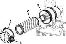
Remove the cover from the air-cleaner body.
-
Remove the primary air filter (Figure 62).
Important: Do not clean and reuse a used element because of possible damage to the filter element.
-
Inspect the new filter for shipping damage, checking the sealing end of the filter and the body.
Important: Do not use a damaged element.
-
Insert the new filter by applying pressure to the outer rim of the element to seat it in the canister.
Important: Do not apply pressure to the flexible center of the filter.
-
Clean the dirt ejection port located in the air-filter cover. Remove the rubber outlet valve from the cover, clean the cavity in the valve, and install the outlet valve into the air-filter cover.
-
Align the dirt ejection port air-filter cover between 3 o’clock to 5 o’clock when viewed from the end, assemble the cover to the canister, and secure the cover.
-
Close and latch the hood.
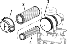
Replacing the Safety Filter
The air filter has a secondary, safety filter element inside the primary air filter to prevent dislodged dust and other items from entering the engine while changing the main element.
Replace the safety filter; never clean it.
Important: Never attempt to clean the safety filter. If the safety filter is dirty, then the primary filter is damaged. Replace both filters.
Servicing the Engine Oil
Oil Specification
Use high-quality engine oil that meets the following specifications:
-
API Classification Level Required: CH-4 or higher
-
Preferred oil: SAE 15W-40 (above 0°F)
-
Alternate oil: SAE 10W-30 or 5W-30 (all temperatures)
Toro Premium Engine Oil is available from your authorized Toro distributor in either 15W-40 or 10W-30 viscosity grades. See the parts catalog for part numbers.
Checking the Engine-Oil Level
| Maintenance Service Interval | Maintenance Procedure |
|---|---|
| Before each use or daily |
|
Important: Check the engine oil daily. If the engine-oil level is above the full mark on the dipstick, the engine oil may be diluted with fuel.If the engine oil level is above the full mark, change the engine oil.
The best time to check the engine oil is when the engine is cool before it has been started for the day. If it has already been run, allow the oil to drain back down to the sump for at least 10 minutes before checking. If the oil level is at or below the Add mark on the dipstick, add oil to bring the oil level to the Full mark. Do not overfill the engine with oil.
Important: Keep the engine oil level between the upper and lower limits on the oil gauge; the engine may fail if you run it with too much or too little oil.
-
Prepare the machine for maintenance; refer to Preparing the Machine for Maintenance.
-
Unlatch and open the hood.
-
Remove the dipstick, wipe it clean, install the dipstick into the tube, and pull it out again. The oil level is correct when it is between the FULL and ADD marks (Figure 64).
-
If the oil level is low, remove the fill cap and add oil until it is between the FULL and ADD marks (Figure 64).
Important: Do not overfill the engine with oil.
-
Install the oil-fill cap and dipstick.
-
Close and latch the hood.
Crankcase Oil Capacity
5.1 L (5.4 US qt) with the filter
Changing the Engine Oil and Filter
| Maintenance Service Interval | Maintenance Procedure |
|---|---|
| After the first 50 hours |
|
| Every 150 hours |
|
-
Prepare the machine for maintenance; refer to Preparing the Machine for Maintenance.
-
Unlatch and open the hood.
-
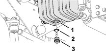
Remove the drain plug and let the oil flow into a drain pan (Figure 66).
-
When all the oil is drained, install the drain plug.
-
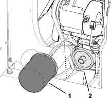
Remove the oil filter (Figure 67).
-
Apply a light coat of clean oil to the oil filter gasket.
-
Thread the oil filter onto the oil filter-adapter until it contacts the mounting surface, and tighten the filter an additional turn.
Important: Do not overtighten the filter.
-
Add oil to the crankcase; refer to Oil Specification and Checking the Engine-Oil Level.
-
Close and latch the hood.
Extended Engine Maintenance
| Maintenance Service Interval | Maintenance Procedure |
|---|---|
| After the first 50 hours |
|
| Every 400 hours |
|
Fuel System Maintenance
Danger
Under certain conditions, diesel fuel and fuel vapors are highly flammable and explosive. A fire or explosion from fuel can burn you and others and can cause property damage.
-
Use a funnel and fill the fuel tank outdoors, in an open area, when the engine is off and is cold. Wipe up any fuel that spills.
-
Do not fill the fuel tank completely full. Add fuel to the fuel tank until the level is 25 mm (1 inch) below the bottom of the filler neck. This empty space in the tank allows the fuel to expand.
-
Never smoke when handling fuel, and stay away from an open flame or where a spark may ignite fuel fumes.
-
Store fuel in a clean, safety-approved container and keep the cap in place.
Bleeding the Fuel System
You must bleed the fuel system before starting the engine if any of the following situations have occurred:
-
Initial start-up of a new machine.
-
Engine has ceased running due to lack of fuel.
-
Maintenance has been performed upon fuel system components; i.e., filter replaced, separator serviced, etc.
-
Park the machine on a level surface and ensure that the fuel tank is at least half full.
-
Open the hood.
-
Turn the key in the ignition switch to the ON position and crank the engine.
Note: The mechanical pump sucks fuel out of the tank, fill the fuel filter and fuel hose and force the air into the engine. This could take some time to fully purge all the air out of the system and the engine might fire erratically until all air is purged out. When all air is purged and the engine is running smoothly, it should be run for a few minutes to ensure that it is fully purged.
If required, a mechanical priming pump is provided at the mechanical fuel pump.
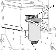
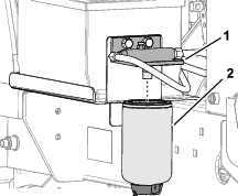
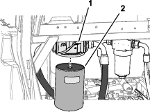
Replacing the Fuel Filter
| Maintenance Service Interval | Maintenance Procedure |
|---|---|
| Every 400 hours |
|
Important: Replace the fuel filter canister periodically to prevent wear of the fuel injection pump plunger or the injection nozzle, due to dirt in the fuel.
-
Prepare the machine for maintenance; refer to Preparing the Machine for Maintenance.
-
Unlatch and open the hood.
-
Place a clean container under the fuel filter canister (Figure 69).
-
Use a hose pinch tool to pinch the inlet and outlet filter hoses to prevent fuel flow in and out of the filter.
-
Loosen the drain valve at the bottom of the filter canister and open the vent screw at the top of the canister mount and drain the fuel from the filter.
-
Tighten the drain valve at the bottom of the filter canister and close the vent screw at the top of the canister mount.
-
Clean the area around the fuel filter and filter head (Figure 69).
-
Remove the filter canister and clean the filter head (Figure 69).
-
Lubricate the gasket on the new filter canister with clean diesel fuel.
-
Install the new filter canister by hand until the gasket contacts the mounting surface.
-
Remove the inlet hose pinch tool and open the vent screw on the top of the filter head.
The fuel filter is gravity-fed and will gradually fill. Once clean fuel purges from the vent screw, close the vent screw and remove the hose pinch tool from the filter outlet hose.
-
Close and latch the hood.
-
Prime the fuel system; refer to Bleeding the Fuel System.
Checking the Fuel Lines and Connections
| Maintenance Service Interval | Maintenance Procedure |
|---|---|
| Every 400 hours |
|
Check the fuel lines and connections for deterioration, damage, or loose connections.
Electrical System Maintenance
Electrical System Safety
-
Disconnect the battery before repairing the machine. Disconnect the negative terminal first and the positive last. Connect the positive terminal first and the negative last.
-
Charge the battery in an open, well-ventilated area, away from sparks and flames. Unplug the charger before connecting or disconnecting the battery. Wear protective clothing and use insulated tools.
Battery Maintenance
Danger
Battery electrolyte contains sulfuric acid, which is fatal if consumed and causes severe burns.
-
Do not drink electrolyte and avoid contact with skin, eyes, or clothing. Wear safety glasses to shield your eyes and rubber gloves to protect your hands.
-
Fill the battery where clean water is always available for flushing the skin.
Warning
Charging the battery produces gasses that can explode.
Never smoke near the battery and keep sparks and flames away from it.
Keep the terminals and the entire battery case clean because a dirty battery slowly discharges. To clean the battery, wash the entire case with a solution of baking soda and water. Rinse it with clear water.
Servicing the Battery
| Maintenance Service Interval | Maintenance Procedure |
|---|---|
| Every 50 hours |
|
Important: When removing the battery, always disconnect the negative (-) cable first.
Important: When installing the battery, always connect the negative (-) cable last.
Under normal operating conditions the battery does not require any further attention. If the machine has been subject to continuous use under high ambient temperature conditions, the battery electrolyte may require adding water.
-
Prepare the machine for maintenance; refer to Preparing the Machine for Maintenance.
-
Unlatch and open the hood.
-
At the left side of the machine, slip back the battery terminal insulators (Figure 70).
-
Remove any corrosion from the battery terminals using a wire brush and to prevent further corrosion.
Note: Check the condition of the battery cables. Install new cables when current ones are showing signs of wear or damage, and tighten any loose connections.
-
Apply Grafo 112X skin-over grease (Toro Part No. 505-47) or petroleum jelly to the terminals.
-
Clean the battery compartment.
-
Close and latch the hood.
Checking the Electrical System
| Maintenance Service Interval | Maintenance Procedure |
|---|---|
| Every 500 hours |
|
Inspect all electrical connections and cables and replace any which are damaged or corroded. Spray a good-quality water inhibitor onto exposed connections to prevent moisture ingress.
Checking the Fuses
-
Prepare the machine for maintenance; refer to Preparing the Machine for Maintenance.
-
Unlatch and open the hood.
-
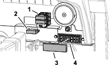
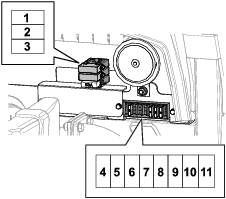
At the back of the bulkhead, remove the fuse-block cover (Figure 71)
-
Check for open fuses.
-
Replace any open fuse with a fuse of equal amperage capacity (Figure 72).
-
Install the fuse-block cover (Figure 71).
-
Close and latch the hood.
Drive System Maintenance
Checking the Tire Pressure
Check the air pressure in the front and rear tires. Refer to the following chart for the correct pressure.
Important: Maintain correct tire pressure in all tires to ensure correct contact with the turf.
| Tires | Tire Type | Recommended Tire Pressures | |||
| General Usage | Turf Conditions | Road Conditions | Maximum Pressure | ||
| Front Axle | 23 x 10.5 - 12 BKT turf pattern | 1 bar (14.5 psi) | 0.7 bar (10 psi) | 1.4 bar (20 psi) | 1.7 bar (25 psi) |
| Rear Axle | 18 x 9.5 - 8 BKT turf pattern | 1 bar (14.5 psi) | 0.7 bar (10 psi) | 1.4 bar (20 psi) | 1.7 bar (25 psi) |
Checking the Torque of the Wheel Nuts
| Maintenance Service Interval | Maintenance Procedure |
|---|---|
| After the first hour |
|
| After the first 10 hours |
|
| Every 50 hours |
|
Torque the wheel nuts in a crossing pattern to the following values:
Front wheels: 200 N∙m (148 ft-lb)
Rear wheels: 100 N∙m (74 ft-lb)
Warning
Failure to maintain proper torque of the wheel nuts could result in personal injury.
Ensure that the wheel nuts are torqued properly.
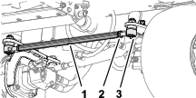
Inspecting the Transmission Control Cable and Operating Mechanism
| Maintenance Service Interval | Maintenance Procedure |
|---|---|
| Every 250 hours |
|
Check the condition and security of the cable and operating mechanism at the speed-control pedals and transmission pump ends.
-
Remove buildup of dirt, grit, and other debris.
-
Ensure that the ball joints are securely anchored and check that the mounting brackets and cable anchors are tight and free from cracks.
-
Inspect end fittings for wear, corrosion, broken springs, and replace if necessary.
-
Ensure that the rubber seals are correctly located and are in good condition.
-
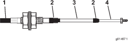
Ensure that the articulating sleeves supporting the inner cable are in good condition and firmly attached to the outer cable assembly at the crimped connections. If there are any signs of cracking or detachment install a new cable immediately.
-
Check that sleeves, rods, and inner cable are free from bends, kinks, or other damage. If they are not, install a new cable immediately.
-
With the engine shut off, operate the pedal controls through the entire range and ensure that the mechanism moves smoothly and freely to the neutral position without sticking or hanging up.
Checking the Rear Wheel Alignment
| Maintenance Service Interval | Maintenance Procedure |
|---|---|
| Every 500 hours |
|
To prevent excessive tire wear and ensure safe machine operation, the front and back of the rear wheels must align within 5 mm (0.20 inch) or less.
-
Turn the steering wheel to align the rear wheels in the straight ahead.
-
Prepare the machine for maintenance; refer to Preparing the Machine for Maintenance.
-
At axle height, measure the distance between the front of the rear wheels and between the rear of the rear wheels.
Note: The wheels are aligned if the difference between the front and rear measurements are 5 mm (0.20 inch) or less.
-
If the difference between the front and rear measurements is greater that 5 mm (0.20 inch), align the rear wheels; refer to Adjusting Rear Wheel Toe-In
Adjusting Rear Wheel Toe-In
-
At the front of the rear wheel, loosen the 2 jam nuts securing the track rod assembly to the rod ends (Figure 75).
-
Align the wheels by rotating the track rod (Figure 75).
Note: Use the wrench flats of the track rod to turn it.
-
At axle height, measure the distance between the front of the rear wheels and between the rear of the rear wheels.
Note: The wheels are aligned if the difference between the front and rear measurements are 5 mm (0.20 inch) or less.
-
Repeat steps 2 and 3 until the wheels are aligned.
-
Tighten the 2 jam nuts to secure the track rod assembly and the rod ends (Figure 75).
Cooling System Maintenance
Cooling System Safety
-
Swallowing engine coolant can cause poisoning; keep out of reach from children and pets.
-
Discharge of hot, pressurized coolant or touching a hot radiator and surrounding parts can cause severe burns.
-
Always allow the engine to cool at least 15 minutes before removing the radiator cap.
-
Use a rag when opening the radiator cap, and open the cap slowly to allow steam to escape.
-
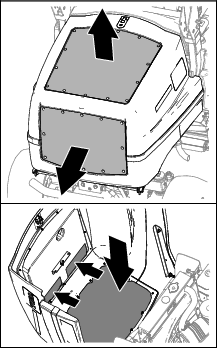
Removing Debris from the Cooling System
| Maintenance Service Interval | Maintenance Procedure |
|---|---|
| Before each use or daily |
|
| Every 100 hours |
|
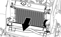
Note: To prevent the engine from overheating, keep the radiator and oil cooler clean. Normally, check them daily and, if necessary, clean any debris off these parts. Check and clean more frequently in dusty and dirty conditions.
-
Prepare the machine for maintenance; refer to Preparing the Machine for Maintenance.
-
Clean the outside of the screens in the hood (Figure 77).
-
Unlatch and open the hood (Figure 77).
-
Clean the inside of the hood screens with compressed air (Figure 77).
-
Thoroughly clean all debris out of the engine area.
-
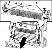
Clean the oil cooler with low-pressure (50 psi) compressed air (Figure 78).
-
Rotate the oil cooler latches inward, and pivot the oil cooler (Figure 78 and Figure 79).
-
Working from the fan side of the radiator , blow out debris with low-pressure (50 psi) compressed air (Figure 79). Repeat this step at the front of the radiator, and again from the fan side. Thoroughly clean both sides of the oil cooler.
Important: Do not use water to clean the radiator and oil cooler.
-
Clean out any debris that may have collected on other parts of the machine with compressed air.
-
Pivot the oil cooler up and secure it with the latches.
-
Close and latch the hood.
Checking the Coolant Level
| Maintenance Service Interval | Maintenance Procedure |
|---|---|
| Before each use or daily |
|
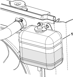
The cooling system is filled with a 50/50 solution of water and permanent ethylene glycol antifreeze. Check the level of coolant in the expansion tank at the beginning of each day before starting the engine.
Caution
If the engine has been running, the pressurized, hot coolant can escape and cause burns.
-
Do not open the radiator cap when the engine is running.
-
Use a rag when opening the radiator cap, and open the cap slowly to allow steam to escape.
-
Prepare the machine for maintenance; refer to Preparing the Machine for Maintenance.
-
Unlatch and open the hood.
-
Check the level of the coolant in the expansion tank (Figure 81).
Note: The coolant level is normal when it is between the marks on the side of the tank.
-
If the coolant level is low, remove the expansion-tank cap and replenish the system.
Note: Do not overfill.
-
Install the expansion-tank cap.
-
Close and latch the hood.
Belt Maintenance
Tensioning the Alternator Belt
| Maintenance Service Interval | Maintenance Procedure |
|---|---|
| After the first 50 hours |
|
| Every 100 hours |
|
-
Prepare the machine for maintenance; refer to Preparing the Machine for Maintenance.
-
Unlatch and open the hood.
-
Check the condition of the belt.
Note: Replace the belt if it is worn or damaged.
-
Apply 10 kg (22 lb) of force against the alternator belt (Figure 83), midway between the pulleys.
Note: The belt should deflect 10 mm (3/8 inch).
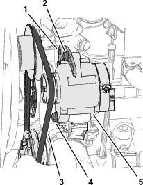
-
If the belt tension is incorrect, perform the following:
-
If belt deflection is less than 10 mm (3/8 inch), loosen the alternator pivot bolt and tension bolt (Figure 83), and reduce the belt tension.
-
If belt deflection is greater than 10 mm (3/8 inch), loosen the alternator pivot bolt and tension bolt (Figure 83), and increase the belt tension.
Note: If needed, loosen the tension bracket bolt (Figure 83).
-
-
Tighten the bolts (Figure 83).
-
Check the deflection of the belt again to ensure correct belt tension.
-
Close and latch the hood.
Controls System Maintenance
Checking the Forward/Reverse Travel Pedal Action
With the engine shut off, operate the forward and reverse travel pedals through the full range of articulation and ensure that the mechanism returns freely to the NEUTRAL position.
Hydraulic System Maintenance
Hydraulic System Safety
-
Seek immediate medical attention if fluid is injected into skin. Injected fluid must be surgically removed within a few hours by a doctor.
-
Ensure that all hydraulic-fluid hoses and lines are in good condition and all hydraulic connections and fittings are tight before applying pressure to the hydraulic system.
-
Keep your body and hands away from pinhole leaks or nozzles that eject high-pressure hydraulic fluid.
-
Use cardboard or paper to find hydraulic leaks.
-
Safely relieve all pressure in the hydraulic system before performing any work on the hydraulic system.
Checking the Hydraulic Lines and Hoses
| Maintenance Service Interval | Maintenance Procedure |
|---|---|
| Before each use or daily |
|
Check the hydraulic lines and hoses for leaks, kinked lines, loose mounting supports, wear, loose fittings, weather deterioration, and chemical deterioration. Make all necessary repairs before operating.
Hydraulic Fluid Specifications
The reservoir is filled at the factory with high-quality hydraulic fluid. Check the level of the hydraulic fluid before you first start the engine and daily thereafter; refer to Checking the Hydraulic Fluid Level.
Recommended hydraulic fluid: Toro PX Extended Life Hydraulic Fluid; available in 19 L (5 US gallon) pails or 208 L (55 US gallon) drums.
Note: A machine using the recommended replacement fluid requires less frequent fluid and filter changes.
Alternative hydraulic fluids: If Toro PX Extended Life Hydraulic Fluid is not available, you may use another conventional, petroleum-based hydraulic fluid having specifications that fall within the listed range for all the following material properties and that it meets industry standards. Do not use synthetic fluid. Consult with your lubricant distributor to identify a satisfactory product.
Note: Toro does not assume responsibility for damage caused by improper substitutions, so use products only from reputable manufacturers who stand behind their recommendation.
| Material Properties: | ||
| Viscosity, ASTM D445 | cSt @ 40°C (104°F) 44 to 48 | |
| Viscosity Index ASTM D2270 | 140 or higher | |
| Pour Point, ASTM D97 | -37°C to -45°C (-34°F to -49°F) | |
| Industry Specifications: | Eaton Vickers 694 (I-286-S, M-2950-S/35VQ25 or M-2952-S) | |
Note: Many hydraulic fluids are almost colorless, making it difficult to spot leaks. A red dye additive for the hydraulic fluid is available in 20 ml (0.67 fl oz) bottles. A bottle is sufficient for 15 to 22 L (4 to 6 US gallons) of hydraulic fluid. Order Part No. 44-2500 from your authorized Toro distributor.
Important: Toro Premium Synthetic Biodegradable Hydraulic Fluid is the only synthetic biodegradable fluid approved by Toro. This fluid is compatible with the elastomers used in Toro hydraulic systems and is suitable for a wide-range of temperature conditions. This fluid is compatible with conventional mineral oils, but for maximum biodegradability and performance, thoroughly flush of conventional fluid from the hydraulic system. The hydraulic fluid is available in 19 L (5 US gallon) pails or 208 L (55 US gallon) drums from your authorized Toro distributor.
Checking the Hydraulic Fluid Level
| Maintenance Service Interval | Maintenance Procedure |
|---|---|
| Before each use or daily |
|
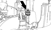
The reservoir is filled at the factory with high-quality hydraulic fluid. The best time to check the hydraulic fluid is when it is cold.
-
Prepare the machine for maintenance; refer to Preparing the Machine for Maintenance.
-
Check the sight-level gauge on the side of the tank.
Note: The hydraulic-fluid level needs to align with the upper mark.
-
If additional hydraulic fluid is needed, remove the storage compartment; refer to Removing the Storage Compartment.
-
Clean the area around the filler neck and the cap of the hydraulic tank (Figure 84).
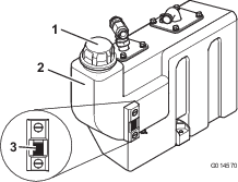
-
Remove the cap and fill the tank with the specified hydraulic fluid to the upper mark on the sight-level gauge.
Important: Do not overfill the tank with hydraulic fluid.
-
Install the cap onto the tank.
-
Install the storage compartment; refer to Installing the Storage Compartment.
Changing the Hydraulic Return Filter
| Maintenance Service Interval | Maintenance Procedure |
|---|---|
| Every 500 hours |
|
| Every 1,000 hours |
|
-
Prepare the machine for maintenance; refer to Preparing the Machine for Maintenance.
-
Unlatch and open the hood.
-
At the left side of the machine, clean the area around the filter head and place a drain pan under the filter (Figure 85).
-
Remove the return filter (Figure 85).
-
Lubricate the gasket of the new return filter with clean hydraulic fluid.
-
Assemble the filter to the filter head, and tighten the filter by hand until the gasket contacts the mounting surface, then rotate it an additional 1/2 turn (Figure 85).
-
Start the engine and let it run for 2 minutes to purge air from the system.
-
Shut off the engine, remove the key, and check for leaks.
-
Close and latch the hood.
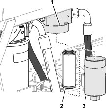
Changing the Transmission Fluid Filter
| Maintenance Service Interval | Maintenance Procedure |
|---|---|
| After the first 50 hours |
|
| Every 500 hours |
|
-
Prepare the machine for maintenance; refer to Preparing the Machine for Maintenance.
-
Unlatch and open the hood.
-
At the left side of the machine, clean the area around the filter head and place a drain pan under the filter housing (Figure 86).
-
Remove the filter housing from the filter head and remove the element (Figure 86).
Note: Discard the filter element.
-
Install a new filter element onto the filter head (Figure 86).
-
Thread the filter housing onto the filter head, and tighten the housing.
-
Start the engine and let it run for 2 minutes to purge air from the system.
-
Shut off the engine, remove the key, and check for leaks.
-
Close and latch the hood.
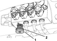
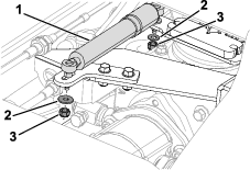
Replacing the Transmission Dampener
| Maintenance Service Interval | Maintenance Procedure |
|---|---|
| Every 2 years |
|
Refer to your authorized Toro distributor for a new dampener kit.
-
Raise the platform; refer to Raising the Platform.
-
Remove the washers and nuts that secure the dampener to the transmission pump and bracket (Figure 87).
-
Remove the dampener.
-
Use the hardware supplied in the dampener kit to secure the new dampener to the transmission pump and bracket.
-
Lower the platform; refer to Lowering the Platform.
Changing the Hydraulic Fluid
| Maintenance Service Interval | Maintenance Procedure |
|---|---|
| Every 500 hours |
|
| Every 1,000 hours |
|
If the fluid becomes contaminated, contact your authorized Toro distributor to flush the system. Contaminated fluid looks milky or black when compared to clean fluid.
Draining the Hydraulic Fluid
-
Park the machine on a level surface, lower the cutting units, shut off the engine, engage the parking brake, and remove the key.
-
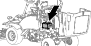
Remove the storage compartment; refer to Removing the Storage Compartment.
-
Align a drain pan under the hydraulic tank, remove the tank drain plug, and fully drain the hydraulic fluid (Figure 88).
-
Install the drain plug with a new seal.
Cleaning the Strainers
-
Remove the storage compartment; refer to Removing the Storage Compartment.
-
Remove the oil tank suction flange to gain access to the suction strainer (Figure 89).
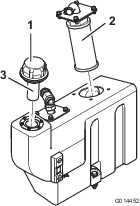
-
Unscrew and remove the strainer and clean with paraffin or petrol before installing (Figure 89).
Hydraulic Fluid Capacity
32 L (8.5 US gallons); refer to Hydraulic Fluid Specifications
Filling the Hydraulic Tank with Fluid
-
Fill the hydraulic tank with the specified hydraulic fluid; refer to Hydraulic Fluid Specifications and Checking the Hydraulic Fluid Level.
Important: Use only hydraulic fluids specified; other hydraulic fluids could damage the system.
-
Run the machine and operate all hydraulic systems until the hydraulic fluid is warm.
-
Check the fluid level and top up as necessary to the upper mark on the sight-level gauge.
-
Install the storage compartment; refer to Installing the Storage Compartment.
Cutting Unit Maintenance
Blade Safety
A worn or damaged blade or bedknife can break, and a piece could be thrown toward you or bystanders, resulting in serious personal injury or death.
-
Inspect the blades and bedknives periodically for excessive wear or damage.
-
Use care when checking the blades. Wear gloves and use caution when servicing them. Only replace or backlap the blades and bedknives; never straighten or weld them.
-
On machines with multiple cutting units, take care when rotating a cutting unit; it can cause the reels in the other cutting units to rotate.
Backlapping the Cutting Units
Warning
Contact with the cutting units or other moving parts can result in personal injury.
-
Keep fingers, hands, and clothing away from the cutting units or other moving parts.
-
Never attempt to turn the cutting units by hand or foot while the engine is running.
Use this process to restore the sharp cutting edges to reels and bedknives, which are needed for good-quality grass cutting.
This process removes a small amount of metal to restore the cutting edges. If the blade edges are seriously worn or damaged, remove the cutting unit and have the reels and bedknife ground.
-
Engage the parking brake, lower the cutting units, shut off the engine, and remove the key.
-
Adjust the reels to the bedknives to obtain light contact.
-
Apply a coat of medium-grade detergent-based carborundum paste to the cutting edges of the reels with a long-handled brush.
80-Grit Carborundum Paste
Part Number
Quantity
63-07-088
45 kg (1 lb)
63-07-086
11 kg (25 lb)
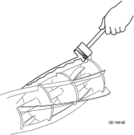
-
Sit on the operator seat, start the engine, and set the engine speed to idle.
Warning
If you touch the cutting units when the engine is running, the cutting unit could seriously injure you.
-
Ensure that the area surrounding the cutting units is clear of people.
-
Keep hands and feet clear of the cutting units during the period when the mower engine is running.
-
-
Press cutting unit drive switch to the REVERSE (backlap) position for a short period. Listen to the grinding action.
-
Operate the cutting unit drive switch to the OFF position. When the cutting unit stops running, shut off the engine and remove the key.
-
Thoroughly clean the blade edges and adjust the bedknives to the reels.
-
While rotating the reels by hand, check along the cutting edges that the reel can cleanly cut a thin piece of paper.
-
If further back lapping is needed, repeat steps 2 through 8.
-
Thoroughly clean off all traces of the carborundum paste from the reels and bedknives.
Grinding the Cutting Units
-
Grind reel blades or bedknives to correct excessively rounded or distorted reel edges or bedknife edges.
Important: Replace the bedknives at the end of their wear life.
-
Grind new blades on their holders prior to fitting.
-
When grinding reel blades or the bedknives are needed, it is essential that they are ground at the same time.
Note: The only exception to this rule is when a new reel is installed, in which case only grind the bedknife.
-
Have your authorized Toro dealer grind your reel blades and bedknives on a quality, well-maintained reel/bedknife grinding machine.
Chassis Maintenance
Inspecting the Seat Belt
| Maintenance Service Interval | Maintenance Procedure |
|---|---|
| Before each use or daily |
|
-
Inspect the seat belt for wear, cuts, and other damage. Replace the seat belt(s) if any component does not operate properly.
-
Clean the seat belt as necessary.
Checking the Fasteners
| Maintenance Service Interval | Maintenance Procedure |
|---|---|
| Before each use or daily |
|
Check the machine for loose and missing fasteners.
Note: Tighten any loose fasteners; replace any missing fasteners.
Extended Maintenance
| Maintenance Service Interval | Maintenance Procedure |
|---|---|
| Every 250 hours |
|
| Every 2 years |
|
Disposing of Waste
Engine oil, batteries, hydraulic fluid, and engine coolant are pollutants to the environment. Dispose of these according to your local regulations.
When disposing of hazardous waste products, take them to an authorized disposal site. Do not allow waste products to contaminate surface water, drains, or sewage systems.
Important: Dispose of hazardous substances correctly.Do not dispose of batteries with a separate collection mark into general waste.When disposing of hazardous waste products, take them to an authorized disposal site.
Cleaning
Washing the Machine
Wash the machine as needed using water alone or with a mild detergent. You may use a rag when washing the machine.
Important: Do not use brackish or reclaimed water to clean the machine.
Important: Do not use power-washing equipment to wash the machine. Power-washing equipment may damage the electrical system, loosen important decals, or wash away necessary grease at friction points. Avoid excessive use of water near the control panel, engine, and battery.
Important: Do not wash the machine with the engine running. Washing the machine with the engine running may result in internal engine damage.
Storage
Storage Safety
-
Shut off the engine, remove the key, and wait for all movement to stop before you leave the operator’s position. Allow the machine to cool before adjusting, servicing, cleaning, or storing it.
-
Do not store the machine or fuel container where there is an open flame, spark, or pilot light, such as on a water heater or other appliance.
Preparing the Traction Unit
-
Park the machine on a level surface, lower the cutting units, engage the parking brake, shut off the engine, and remove the key.
-
Thoroughly clean the traction unit, cutting units, and the engine.
-
Check the tire pressure; refer to Checking the Tire Pressure.
-
Check all fasteners for looseness; tighten them as necessary.
-
Grease or oil all grease fittings and pivot points. Wipe up any excess lubricant.
-
Lightly sand and use touch-up paint on painted areas that are scratched, chipped, or rusted. Repair any dents in the metal body.
Preparing the Engine
-
Drain the oil from the engine and install the drain plug.
-
Remove and discard the oil filter. Install a new oil filter.
-
Fill the engine with specified motor oil.
-
Start the engine and run it at idle speed for approximately 2 minutes.
-
Shut off the engine and remove the key.
-
Flush the fuel tank with fresh, clean fuel.
-
Secure all fuel-system fittings.
-
Thoroughly clean and service the air-cleaner assembly.
-
Seal the air-cleaner inlet and the exhaust outlet with weatherproof tape.
-
Check the antifreeze protection and add a 50/50 solution of water and ethylene glycol antifreeze as needed for the expected minimum temperature in your area.
Preparing the Electrical System
-
Service the battery and cables as follows; refer to Servicing the Battery.
-
Remove the battery terminals from the battery posts.
-
Clean the battery, terminals, and posts with a wire brush and baking-soda solution.
-
Coat the cable terminals and battery posts with Grafo 112X skin-over grease (Toro Part No. 505-47) or petroleum jelly to prevent corrosion.
-
Slowly charge the battery every 60 days for 24 hours to prevent lead sulfation of the battery.
Troubleshooting
| Problem | Possible Cause | Corrective Action |
|---|---|---|
| There are areas of uncut grass at the overlap between cutting units. |
|
|
| There are full-width ridge lines in the cut across the direction of travel. |
|
|
| There are ridge lines in the cut grass, across the direction of travel, over the cutting width of 1 cutting unit. |
|
|
| There is a step in the cut grass height at the point of overlap between cutting units. |
|
|
| There are some uncut or poorly cut strands of grass. |
|
|
| There are lines of uncut or badly cut grass in the direction of travel. |
|
|
| There is scalping of the turf. |
|
|
| There is excessive bedknife wear. |
|
|
| The engine does not start with the ignition key. |
|
|
| The battery has no power. |
|
|
| The hydraulic fluid is overheating. |
|
|
| The brake system does not operate correctly. |
|
|
| There is a lack of steering. |
|
|
| There is no machine movement in forward or reverse. |
|
|
| The machine creeps forward or backward in neutral. |
|
|
| There is excessive noise in the hydraulic system. |
|
|
| After an initial period of satisfactory operation, the machine loses power. |
|
|
| A reel ‘knocks’ while rotating. |
|
|
| 1 reel rotates slowly. |
|
|
| A cutting unit fails to lift out of work. |
|
|
| The cutting units do not follow the contours of the ground. |
|
|
| The cutting units fail to start up when lowered into work. |
|
|
| The reels rotate in the wrong direction. |
|
|