Maintenance
Recommended Maintenance Schedule(s)
| Maintenance Service Interval | Maintenance Procedure |
|---|---|
| After the first 20 hours |
|
| Before each use or daily |
|
| After each use |
|
| Every 50 hours |
|
| Every 500 hours |
|
| Before storage |
|
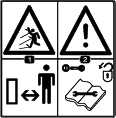
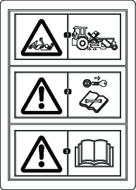
Caution
If you leave the key in the switch, someone could accidently start the engine and seriously injure you or other bystanders.
Remove the key from the switch before you perform any maintenance.
Maintenance Safety
-
Before adjusting, cleaning, servicing, or leaving the machine, do the following:
-
Position the machine on a level surface.
-
Move the throttle switch to the low-idle position.
-
Disengage the PTO (if applicable).
-
Ensure that the traction is in neutral.
-
Engage the parking brake.
-
Shut off the engine of the traction unit and remove the key.
-
Wait for all moving parts to stop.
-
Allow machine components to cool before performing maintenance.
-
-
Perform only those maintenance instructions described in this manual. If major repairs are ever needed or assistance is desired, contact an authorized Bullseye distributor.
-
Ensure that the machine is in safe operating condition by keeping nuts, bolts, and screws tight.
-
If possible, do not perform maintenance while the engine is running. Keep away from moving parts.
-
Carefully release pressure from components with stored energy.
-
Support the machine with blocks or storage stands when working beneath it. Never rely on the hydraulic system to support the machine.
-
Never crawl under the attachment. If necessary, tilt the attachment.
-
Ensure that all guards are installed and secured after maintaining or adjusting the machine.
-
To ensure safe, optimal performance of the machine, use only genuine Bullseye replacement parts. Replacement parts made by other manufacturers could be dangerous, and such use could void the product warranty.
Greasing the Attachment
| Maintenance Service Interval | Maintenance Procedure |
|---|---|
| After the first 20 hours |
|
| After each use |
|
| Every 50 hours |
|
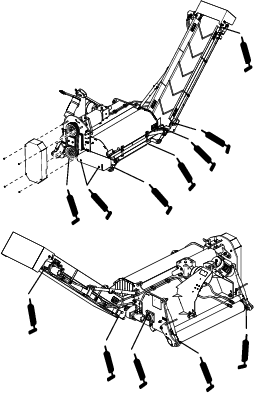
The attachment has grease fittings that you must lubricate regularly with No. 2 lithium grease. Also, lubricate the attachment immediately after every washing and after long periods without use.
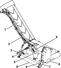
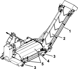
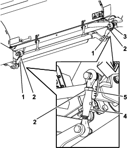
Grease the machine at the following bearing locations (Figure 27).
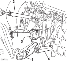
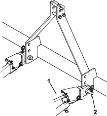
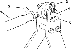
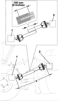
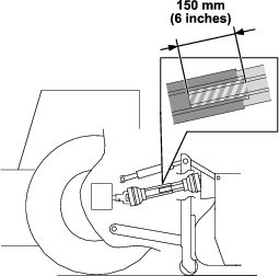
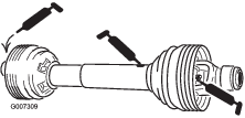
Grease the PTO driveshaft at the following locations (Figure 28).
Checking the Gearbox Lubrication
| Maintenance Service Interval | Maintenance Procedure |
|---|---|
| After the first 20 hours |
|
| Before each use or daily |
|
| Every 50 hours |
|
Allow the gearbox to cool before checking the lubrication.
-
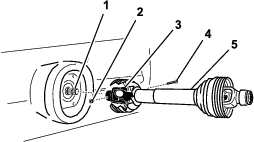
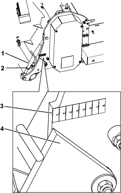
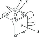
Clean debris from the fill plug to avoid contamination (Figure 29).
-
Remove the fill plug to relieve trapped air.
-
Remove the socket-head bolt on the rear of the gearbox.
-
If no fluid spills out, add more fluid until it comes out.
-
Install the socket-head bolt on the rear of the gearbox (Figure 29).
-
Install the fill plug.
Changing the Gearbox Lubrication
| Maintenance Service Interval | Maintenance Procedure |
|---|---|
| Every 500 hours |
|
The gearbox is filled with SAE140 gear oil or equivalent.
-
Clean debris from the fill plug and the drain plug to avoid contamination (Figure 29).
-
Remove the fill plug to relieve trapped air.
-
Position a short drain pan under the drain plug and remove the drain plug.
Note: The high viscosity of cool oil extends the drain time (approximately 30 minutes).
-
After oil is completely drained, install the drain plug.
-
Remove the socket-head bolt on the back of the gearbox.
-
Fill the gearbox until fluid comes out the back hole.
-
Install the socket-head bolt on the rear of the gearbox (Figure 29).
-
Install the fill plug.
Inspecting the Belts
The drive belt(s) on the machine are durable. However, the normal exposure to UV radiation, ozone or incidental exposure to chemicals can deteriorate the rubber compounding over time and lead to premature wear or material loss (i.e. chunking).
Annual belt inspection is highly recommended for signs of wear, excessive cushion cracks, or large embedded debris with replacement when needed.
Adjusting the V-Belt Tension
| Maintenance Service Interval | Maintenance Procedure |
|---|---|
| After the first 20 hours |
|
| Every 50 hours |
|
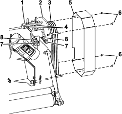
Make sure that the belts are properly tensioned to ensure that the machine is operating correctly and to prevent unnecessary wear.
This machine is equipped with adjustable tension pulleys that keep the V-belts tight. Depending on the intensity of using the machine, the driveline could be affected by the wear of the belts.
-
Remove the belt cover.
-
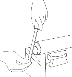
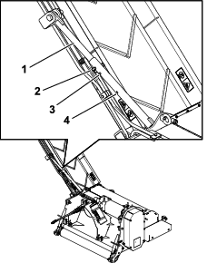
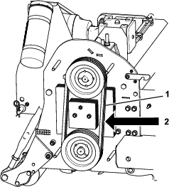
Check the tension of the V-belts by pushing point A with a pressure of 7.5 kg (16-1/2 lb). Proper tension of the belts allows 12.4 mm (1/2 inch) of deflection on each belt (Figure 30).
Note: If the tension is correct, install the belt cover (Figure 31).
-
If the tension is not correct, loosen the locknuts under the plate (Figure 31).
-
Loosen the bolts in the slots (Figure 31).
-
Adjust the locknuts on top to adjust the tension of the belts.
-
Check the belt tension and if needed, continue to adjust the top locknuts.
-
Tighten the lower locknuts under the plate (Figure 31).
-
Tighten the top locknuts.
-
Tighten the bolts in the slots.
-
Install the belt cover.
Adjusting the Conveyor Belt Alignment
If the conveyor belt starts slipping or moving sideways after use or after new installation, adjust the conveyor belt tension.
-
Check if the rollers and the inside of the conveyor belt are clean. If necessary clean the rollers and remove any dirt inside.
-
Release the tension of the conveyor belt by loosening the left and right screws.
-
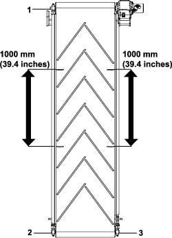
Mark both sides of the belt with 2 measurement marks a distance of 1000 mm (39-13/32 inch) apart; refer to Figure 32.
-
Adjust the screws on both sides evenly till the distance between the marks has increased to an initial dimension of 1004 mm (39-1/2 inch).
Note: Make the adjustments evenly on both sides in small steps.
-
Run the conveyor belt only slowly to detect any belt movement and before any damage occurs.
-
If the belt keeps slipping, adjust the screws evenly till a maximum of 1010 mm (39-13/16 inch).
-
If the conveyor belt tends to move to the left, give a little more tension on the lower left adjustment. If the conveyor belt moves to the right, give a little more tension to the lower right adjustment.
Note: Carry out the adjustments in small steps.
Belt Tensioning Belt movement The belt moves to the left. The belt moves to the right. Adjustment Tighten the lower left screw. Tighten the lower right screw. -
After each adjustment, allow the conveyor belt to rotate for at least 10 rotations to position itself to the new alignment before making any further corrections.
-
If the belt is working properly again, securely lock the screws in place.
Cleaning the Machine
| Maintenance Service Interval | Maintenance Procedure |
|---|---|
| After each use |
|
Important: Do not use brackish or reclaimed water to clean the machine.
-
After daily use, thoroughly wash the machine with a garden hose (without a nozzle) to avoid contamination and seal and bearing damage due to excessive water pressure.
Note: Use a brush to help remove thick layered, dried, or compacted dirt and debris.
-
Use a mild detergent to clean the covers.
-
Inspect the machine for damage, leaking oil, and component wear.
-
After cleaning the machine, grease all drive lines and roller bearings; refer to Greasing the Attachment.
Installing the Cutter Knives
-
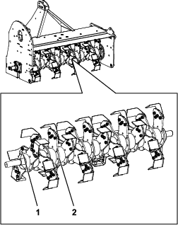
Install the far left knives with the L pointing to the right.
-
Install all remaining knives with the L pointing to the left.
Installing Scarifying Knives
This machine is equipped with cutting knives, but you can also equip it with scarifying knives (if required) for scarifying the subsoil.
You can set the distance between the scarifying knives at the following 4 positions:
-
20 mm (0.79 inches)
-
40 mm (1.6 inches)
-
60 mm (2.36 inches)
-
80 mm (3.15 inches)
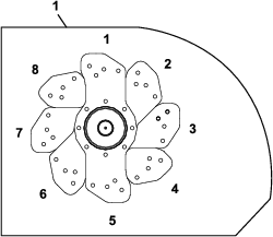
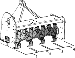
There are 8 rows on the rotor (Figure 34). Each row has 4 plates. When you stand behind the attachment, plate section 1 is the extreme left plate and plate section 4 is the extreme right plate (Figure 35).
Note: Do not forget the weights. Without the weights, the machine could become unbalanced and that could cause damage to the field and the machine. The following tables show the distribution.
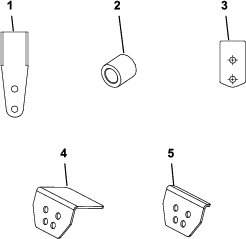
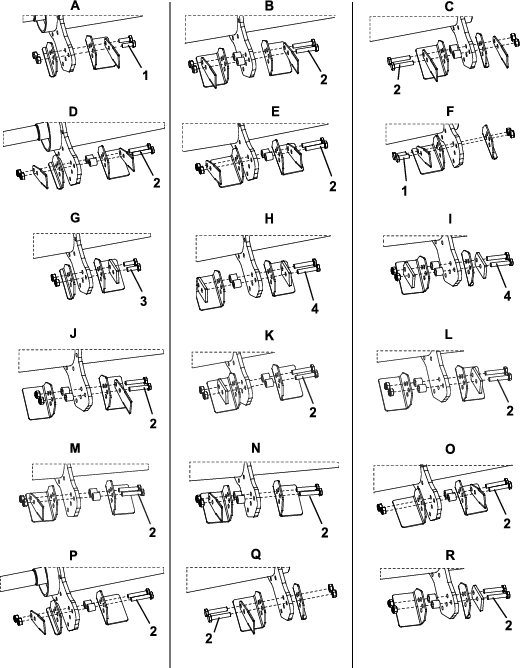
Use the tables below to select the spacing. The letters in the tables and Figure 37 show what parts to assemble in each row.
Note: There are different parts used in the row at the different plate sections.
| Plate Section | ||||
| Row | 1 | 2 | 3 | 4 |
| 1 | A | B | B | B |
| 2 | B | B | B | B |
| 3 | B | B | B | B |
| 4 | B | B | B | C |
| 5 | D | E | E | E |
| 6 | E | E | E | E |
| 7 | E | E | E | E |
| 8 | E | E | E | F |
| Part | Quantity |
| Knife | 62 |
| Bushing | 60 |
| Bolt (M10 x 30) | 4 |
| Bolt (M10 x 55) | 60 |
| Nut (M10) | 64 |
| Large paddle | 60 |
| Small paddle | 4 |
| Plate Section | ||||
| Row | 1 | 2 | 3 | 4 |
| 1 | G | H | H | H |
| 2 | H | H | H | H |
| 3 | H | H | H | H |
| 4 | H | H | H | I |
| 5 | D | E | E | E |
| 6 | E | E | E | E |
| 7 | E | E | E | E |
| 8 | E | E | E | Q |
| Part | Quantity |
| Knife | 31 |
| Counterweight | 31 |
| Bushing | 60 |
| Bolt (M10 x 35) | 2 |
| Bolt (M10 x 55) | 32 |
| Bolt (M10 x 60) | 30 |
| Nut (M10) | 64 |
| Large paddle | 60 |
| Small paddle | 4 |
| Plate Section | ||||
| Row | 1 | 2 | 3 | 4 |
| 1 | G | N | J | L |
| 2 | N | J | L | N |
| 3 | J | L | N | J |
| 4 | L | N | J | R |
| 5 | P | M | M | M |
| 6 | M | M | M | M |
| 7 | M | M | M | M |
| 8 | M | M | M | Q |
| Part | Quantity |
| Knife | 21 |
| Counterweight | 11 |
| Bushing | 60 |
| Bolt (M10 x 35) | 2 |
| Bolt (M10 x 55) | 62 |
| Nut (M10) | 64 |
| Large paddle | 60 |
| Small paddle | 4 |
| Plate Section | ||||
| Row | 1 | 2 | 3 | 4 |
| 1 | G | L | L | L |
| 2 | L | L | L | L |
| 3 | L | L | L | L |
| 4 | L | L | L | R |
| 5 | P | E | E | E |
| 6 | E | E | E | E |
| 7 | E | E | E | E |
| 8 | E | E | E | Q |
| Part | Quantity |
| Knife | 16 |
| Counterweight | 16 |
| Bushing | 60 |
| Bolt (M10 x 35) | 2 |
| Bolt (M10 x 55) | 62 |
| Nut (M10) | 64 |
| Large paddle | 60 |
| Small paddle | 4 |

 , which means
Caution, Warning, or Danger—personal safety instruction. Failure
to comply with these instructions may result in personal injury or
death.

