To create a CE bagger, install this kit on the Blower and Drive Kit (Toro Model 78483, 78486, 78433, or 78436 for 122 cm mower decks or Toro Model 78484, 78487, 78434, or 78437 for 132 cm mower decks), and with the E-Z Vac™ Twin Bagger Kit (Toro Model 78481 or 78431).
Installation
Preparing the Machine
-
Park the machine on a level surface.
-
Engage the parking brake.
-
Shut off the engine and remove the key.
-
Thoroughly clean the mower deck.
Note: Remove all the debris to ensure that the kit will fit properly.
-
Repair all bent or damaged areas and replace any missing parts.
-
Lower the mower deck to the lowest height-of-cut position; refer to the mower Operator’s Manual.
Remove the Discharge Chute
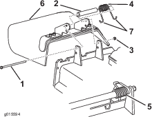
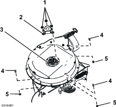
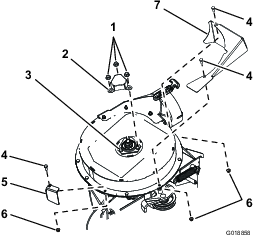
Removing the Belt Cover and Brackets
Removing the Belt Cover
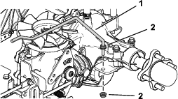
If installed, remove the belt cover as follows:
-
Rotate the bolt that secures the belt cover to the deck counterclockwise to loosen it (Figure 2).
-
Remove the belt cover and bolt from the mounting bracket (Figure 2).
Note: Retain the belt cover and bolt for installation when operating the mower with the blower accessory removed.
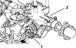
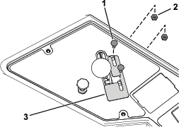
Removing the Cover Mounting Bracket
-
Remove the 2 bolts and 2 flange nuts that secure the cover mounting bracket to the deck (Figure 2).
-
Remove the bracket.
Note: Retain the cover mounting bracket, bolts, and flange nut for installation when operating the mower with the blower accessory removed.
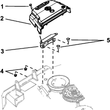
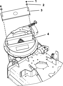
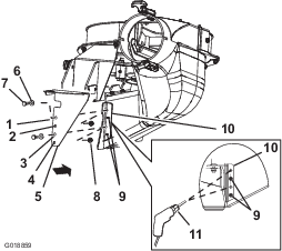
Removing the Existing Lower Support Rod
Remove the carriage bolt and nut from the existing lower support rod and remove it (Figure 3).
Note: Retain the carriage bolt and nut.
Installing the New Lower Support Rod
Install the new lower support rod using the previously removed carriage bolt and nut (Figure 4).
Installing the Rear Support Rods
Removing the Blower Kit Parts
Removing the Belt Cover for the Blower
If the blower kit is installed on the machine, remove the belt cover installed from the blower and drive kit as follows:
Removing the Belt Cover Bracket
If the blower kit is installed on the machine, remove the belt cover bracket installed from the blower and drive kit as follows:
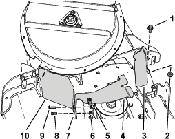
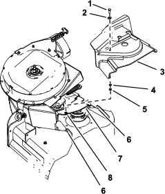
Removing the Shaft Cover and Hardware
-
Remove the 3 serrated nuts that secure the shaft cover to the blower assembly (Figure 9).
Note: Do not loosen the bolts and nuts that secure the upper-bearing housing that are beneath the shaft cover.
-
Remove and discard the shaft cover (Figure 9).
-
Remove the 3 hex-head bolts (1/4 x 3/4 inch) and 3 locknuts (1/4 inch) from the blower housing as shown in Figure 9.
Installing the CE Pulley Guard and Belt-Cover Bracket
Parts needed for this procedure:
| CE pulley guard | 1 |
| CE belt-cover bracket | 1 |
| Hex-head bolt (1/4 x 1 inch) | 1 |
| Carriage bolt (1/4 x 3/4 inch) | 1 |
| Flange nut (1/4 inch) | 2 |
| Hex-head bolt (3/8 x 1 inch) | 2 |
| Flange nut (3/8 inch) | 2 |
| Clip nut | 1 |
| Rear guard (122 cm mower deck only) | 1 |
Installing the CE Pulley Guard and Belt-Cover Bracket
-
Align the holes of the CE pulley guard to the hole in the forward deflector bracket and the outboard hole in the forward deck flange (Figure 11).
Note: The CE pulley bracket wraps around the outboard edge of the deflector bracket.
-
Align the CE belt-cover bracket to the holes at the rear side of the forward deck flange (Figure 11).
-
Secure the CE pulley guard and the belt cover bracket to the forward deck flange at the outboard hole with the hex-head bolt (1/4 x 1 inch) and a flange nut (1/4 inch) as shown in Figure 11.
-
Secure the belt-cover bracket to the forward deck flange at the inboard hole with the a carriage bolt (1/4 x 3/4 inch) and a flange nut (1/4 inch) as shown in Figure 11.
-
Align the hole in the rear flange of the CE belt-cover bracket with the hole in the deck where you removed the belt cover bracket in step 1 of Removing the Cover Mounting Bracket; refer to Figure 11.
-
Secure the rear flange of the CE belt-cover bracket to the deck with a hex-head bolt (3/8 x 1 inch) and a flange nut (3/8 inch) as shown in Figure 11.
-
Align the clip nut with the hole in the top of the CE belt-cover bracket, and push the clip nut onto the bracket (Figure 11).
-
Loosely install the rear guard to the mower deck using a hex-head bolt (3/8 x 1 inch) and a flange nut (3/8 inch) as shown in Figure 11.
Tighten the fasteners after you install the blower; refer to Installing the Blower.
Important: This step applies to 122 cm mower decks only.
Installing the CE Pulley Guard and Belt-Cover Bracket
-
Align the holes of the CE pulley guard to the hole in the forward deflector bracket and the outboard hole in the forward deck flange (Figure 12).
Note: The CE pulley bracket wraps around the outboard edge of the deflector bracket.
-
Align the CE belt-cover bracket to the holes at the rear side of the forward deck flange (Figure 12).
-
Secure the CE pulley guard and the belt cover bracket to the forward deck flange at the outboard hole with the hex-head bolt (1/4 x 1 inch) and a flange nut (1/4 inch) as shown in Figure 12.
-
Secure the belt-cover bracket to the forward deck flange at the inboard hole with the a carriage bolt (1/4 x 3/4 inch) and a flange nut (1/4 inch) as shown in Figure 12.
-
Align the clip nut with the hole in the top of the CE belt-cover bracket, and push the clip nut onto the bracket (Figure 12).
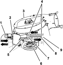
Installing the CE Upper Guards
Parts needed for this procedure:
| CE shaft guard | 1 |
| CE forward guard | 1 |
| CE tensioner guard | 1 |
Installing the CE Shaft Guard
Installing the CE Shaft Guard
Install the CE shaft guard to the blower assembly using 2 nuts and 2 washers (Figure 14).
Installing the CE Upper Guards
-
Align the CE forward guard to the upper blower housing (Figure 13).
-
Secure the CE forward guard to the upper blower housing with a hex-head bolt (1/4 x 3/4 inch) and a locknut (1/4 inch) as shown in Figure 13.
-
Align the CE tensioner guard to the upper blower housing (Figure 13).
-
Secure the CE tensioner guard to the upper blower housing with 2 hex-head bolt (1/4 x 3/4 inch) and 2 locknuts (1/4 inch) as shown in Figure 13.
Installing the CE Lower Guard
Parts needed for this procedure:
| CE lower guard | 1 |
| Hex-head bolt (1/4 x 3/4 inch) | 2 |
| Washer (1/4 x 5/8) | 2 |
| Locknut (1/4 inch) | 2 |
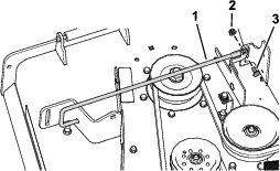
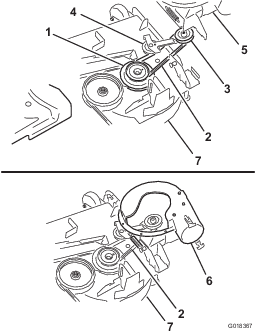
Removing the Blower
If installed remove the blower assembly from the mower deck as follows:
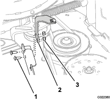
-
Pull the spring loaded idler pulley away from the fixed spring post, and remove the belt from the idler pulley (Figure 15).
-
Move the idler pivot bracket toward the fixed spring post. remove the hook of the spring from the idler spring post (Figure 15).
-
Route the belt beneath the idler pulley (Figure 16).
-
Remove the belt from drive pulley (Figure 16).
-
Move the blower latch pin to the open position and swing the blower outward (Figure 15).
-
Remove the blower and belt from the mower deck.
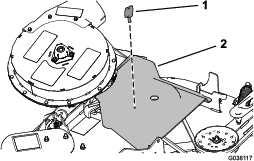
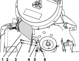
Drilling the Mounting Holes for the CE Lower Guard
-
Align the lower CE lower guard to the blower-chute bracket as shown in Figure 17.
-
Align hole 2 and hole 4 of the lower CE lower guard to the rivet tails protruding through the blower-chute bracket (Figure 17).
Note: Ensure that the flange of the CE lower guard (the flange with the holes) is flat against the blower-chute bracket.
-
Mark the outline of hole 1 and hole 3 of the CE lower guard on the blower-chute bracket, and remove the CE guard (Figure 17).
-
Locate the marks on the blower-chute bracket, and center-punch the locations.
-
Drill 7 mm (1/4 inch) holes in the blower-chute bracket at the 2 center-punch marks (Figure 17).
Installing the CE Lower Guard
Note: Install the CE lower guard with the blower assembly removed from the mower deck; refer to the E-Z Vac™ Blower and Drive Kit Installation Instructions.
-
Align the CE lower guard to the blower-chute bracket (Figure 17).
-
Align hole 2 and hole 4 of the CE lower guard to the rivet tails protruding through the blower-chute bracket (Figure 17).
-
Secure the CE lower guard to the blower with 2 hex-head bolts (1/4 x 3/4 inch), 2 washers, and 2 locknuts (1/4 inch) through hole 1 and hole 4 of the CE guard (Figure 17).
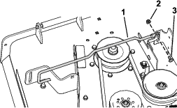
Installing the Blower
If you removed the blower, install the blower assembly to the mower deck as follows:
Note: Refer to the 48in or 52in E-Z Vac™ Twin Soft Bagger Owner’s Manual.
-
Align the blower belt around the pulley of the blower (Figure 16).
-
Align the pivot pin on the blower with the pivot pin hole in the deck and lower the blower onto deck.
-
Open the blower latch pin, close the blower to the deck, and secure the latch pin to the chute bracket (Figure 15).
Note: Ensure that the latch pin extends through the hole in chute bracket and the CE pulley guard.
-
Temporarily route the belt beneath the idler pulley (Figure 16).
-
Route the belt around the drive pulley (Figure 16).
-
Move the idler/tension pulley toward the fixed spring post, and install the spring by aligning the spring hook on to the idler spring post (Figure 15).
-
Pull the spring loaded idler/tension pulley away from the fixed spring post, and route the belt around the idler pulley (Figure 16).
Installing the CE Belt Cover
Parts needed for this procedure:
| Hex-head bolt (1/4 x 3/4 inch) | 1 |
| Washer (5/16 x 3/4 inch) | 1 |
| Washer (1/4 x 1/2 inch) | 1 |
| Retainer | 1 |
Installing the CE Belt Cover Bolt
-
Assemble the washer (5/16 x 3/4 inch) to the hex-head bolt (1/4 x 3/4 inch) as shown in Figure 18.
-
Insert the bolt and washer through the hole in the top of the belt cover from the OEM blower and drive kit (Figure 18).
-
From the bottom of the belt cover, assemble the washer (1/4 x 1/2 inch) and retainer over the hex-head bolt threads (Figure 18).
Ensure that the bolt head and washer are positioned flush with the upper surface of the belt cover and the washer and retainer are flush with the bottom surface of the cover.
Installing the Belt Cover
-
Unlatch the blower and pull it out partially.
-
Align the belt cover with notches in the deck flanges (Figure 18).
-
Align the hex-head bolt in the cover with the clip nut on the belt-cover bracket.
-
Secure the belt cover to the cover bracket with the hex-head bolt (Figure 18).
-
Open the blower latch pin, close the blower to the deck, and secure the latch pin to the chute bracket.
Installing the Throttle Plate and Adjusting the Engine Speed
Parts needed for this procedure:
| Carriage bolt (#10 x 5/8 inch) | 2 |
| Locknut (#10) | 2 |
| Throttle plate | 1 |
-
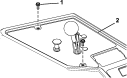
Remove the 2 screws securing the control panel, and lift the control panel from the console (Figure 19).
-
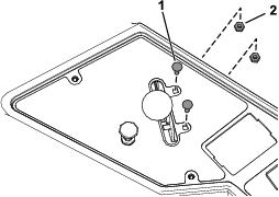
Remove the 2 bolts and 2 nuts securing the throttle lever to the control panel (Figure 20).
Discard the 2 bolts and 2 nuts.
-
Loosely secure the new throttle plate and throttle lever to the control panel using the 2 carriage bolts (#10 x 5/8 inch) and 2 locknuts (#10) as shown in Figure 21.
-
Locate your mower and bagger combination on the Declaration of Conformity.
-
Set the engine speed (rpm) listed in the corresponding column in the Declaration of Conformity by doing the following:
-
Move the throttle plate forward or rearward, and move the throttle lever until it reaches the correct engine speed (rpm).
-
Tighten the 2 carriage bolts (#10 x 5/8 inch) and 2 locknuts (#10).
-
-
Secure the control panel to the console using the previously removed 2 screws (Figure 19).