
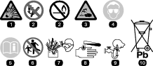
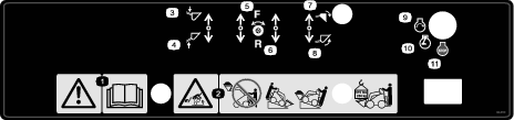
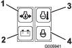
 , which means Caution, Warning,
or Danger—personal safety instruction. Failure to comply with
these instructions may result in personal injury or death.
, which means Caution, Warning,
or Danger—personal safety instruction. Failure to comply with
these instructions may result in personal injury or death.


Maintenance
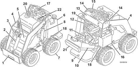
Note: Determine the left and right sides of the machine from the normal operating position.
Caution
If you leave the key in the switch, someone could accidently start the engine and seriously injure you or other bystanders.
Remove the key from the switch before you perform any maintenance.
Maintenance Safety
-
Park the machine on a level surface, disengage the auxiliary hydraulics, lower the attachment, engage the parking brake (if equipped), shut off the engine, and remove the key. Wait for all movement to stop and allow the machine to cool before adjusting, cleaning, storing, or repairing it.
-
Clean up oil or fuel spills.
-
Do not allow untrained personnel to service the machine.
-
Use jack stands to support the components when required.
-
Carefully release pressure from components with stored energy; refer to Relieving Hydraulic Pressure.
-
Disconnect the battery before making any repairs; refer to Servicing the Battery.
-
Keep your hands and feet away from the moving parts. If possible, do not make adjustments with the engine running.
-
Keep all parts in good working condition and all hardware tightened. Replace all worn or damaged decals.
-
Do not tamper with the safety devices.
-
Use only Toro-approved attachments. Attachments can change the stability and the operating characteristics of the machine. You may void the warranty if you use the machine with unapproved attachments.
-
Use only genuine Toro replacement parts.
-
If any maintenance or repair requires the loader arms to be in the raised position, secure the arms in the raised position with the hydraulic-cylinder lock(s).
Recommended Maintenance Schedule(s)
| Maintenance Service Interval | Maintenance Procedure |
|---|---|
| After the first 8 hours |
|
| After the first 50 hours |
|
| Before each use or daily |
|
| Every 25 hours |
|
| Every 75 hours |
|
| Every 100 hours |
|
| Every 200 hours |
|
| Every 400 hours |
|
| Every 1,500 hours |
|
| Yearly |
|
| Yearly or before storage |
|
Important: Refer to your engine owner's manual for additional maintenance procedures.
Pre-Maintenance Procedures
Using the Cylinder Locks
Warning
The loader arms may lower when in the raised position, crushing anyone under them.
Install the cylinder lock(s) before performing maintenance that requires raised loader arms.
Installing the Cylinder Locks
-
Remove the attachment.
-
Raise the loader arms to the fully raised position.
-
Shut off the engine and remove the key.
-
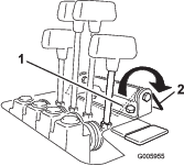
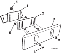
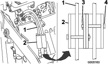
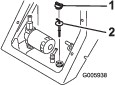
Position a cylinder lock over each lift-cylinder rod (Figure 20).
-
Secure each cylinder lock with a clevis pin and cotter pin (Figure 20).
-
Slowly lower the loader arms until the cylinder locks contact the cylinder bodies and rod ends.
Removing and Storing the Cylinder Locks
Important: Remove the cylinder locks from the rods and fully secure them in the storage position before operating the machine.
-
Start the engine.
-
Raise the loader arms to the fully raised position.
-
Shut off the engine and remove the key.
-
Remove the clevis pin and cotter pin securing each cylinder lock.
-
Remove the cylinder locks.
-
Lower the loader arms.
-
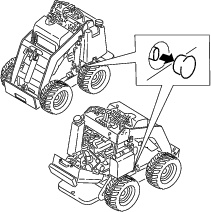
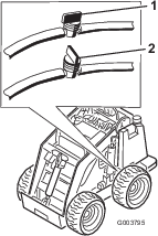
Install the cylinder locks over the hydraulic hoses and secure them with the clevis pins and cotter pins (Figure 21).
Accessing Internal Components
Warning
Opening or removing covers, hoods, and screens while the engine is running could allow you to contact moving parts, seriously injuring you.
Before opening any of the covers, hoods, and screens, shut off the engine, remove the key from the key switch, and allow the engine to cool.
Removing the Front-Access Cover
-
Park the machine on a level surface and engage the parking brake.
-
Raise the loader arms and install the cylinder locks.
Note: If you must remove the front-access cover without raising the loader arms, be very careful not to damage the cover or hydraulic hoses as you maneuver the cover out from under the arms.
-
Shut off the engine and remove the key.
-
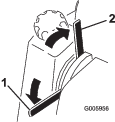
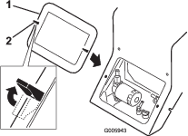
Release the 2 locking tabs (Figure 22, top, left tab illustrated).
-
Pull the cover off the machine.
-
When finished, replace the front-access cover and secure it with the 2 locking tabs.
Opening the Rear-Access Cover
-
Park the machine on a level surface, engage the parking brake, and lower the loader arms.
-
Shut off the engine and remove the key.
-
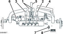
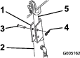
Release the 2 locking tabs on top of the rear-access cover (Figure 23).
-
Remove the bolt located next to the right locking tab (Figure 23).
-
Grasping the handle, pull the cover up and back to swing it open (Figure 23).
-
When finished, close the rear-access cover by swinging it up and seating it in place.
-
Secure it with the 2 locking tabs and bolt.
Lubrication
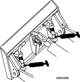
Greasing the Machine
| Maintenance Service Interval | Maintenance Procedure |
|---|---|
| Before each use or daily |
|
Grease Type: General-purpose grease
-
Park the machine on a level surface, engage the parking brake (if equipped), and lower the loader arms.
-
Shut off the engine and remove the key.
-
Clean the grease fittings with a rag.
-
Connect a grease gun to each fitting (Figure 24 and Figure 25).
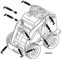
-
Pump grease into the fittings until grease begins to ooze out of the bearings (approximately 3 pumps).
-
Wipe up any excess grease.
Engine Maintenance
Engine Safety
-
Shut off the engine before checking the oil or adding oil to the crankcase.
-
Do not change the engine governor setting or overspeed the engine.
-
Keep your hands, feet, face, clothing, and other body parts away from the muffler and other hot surfaces.
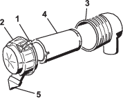
Servicing the Air Cleaner
| Maintenance Service Interval | Maintenance Procedure |
|---|---|
| Every 200 hours |
|
-
Park the machine on a level surface, engage the parking brake (if equipped), and lower the loader arms.
-
Shut off the engine and remove the key.
-
Release the latches on the air cleaner and pull the air-cleaner cover off the air-filter body (Figure 26).
-
Squeeze the dust cap sides to open it and knock the dust out.
-
Clean the inside of the air-cleaner cover with compressed air that is under 205 kPa (30 psi).
Important: Do not use compressed air on the air-cleaner body.
-
Gently slide the filter out of the air-filter body (Figure 26).
Note: Avoid knocking the filter into the side of the body.
Important: Do not attempt to clean the filter.
-
Inspect the new filter for tears, an oily film, or damage to the rubber seal. Look into the filter while shining a bright light on the outside of the filter; holes in the filter appear as bright spots.
If the filter is damaged, do not use it.
-
Carefully install the filter (Figure 26).
Note: Ensure that the filter is fully seated by pushing on the outer rim of the filter while installing it.
Important: Do not press on the soft inside area of the filter.
-
Install the air-cleaner cover with the dust cap oriented downward and secure the latches (Figure 26).
Servicing the Engine Oil
| Maintenance Service Interval | Maintenance Procedure |
|---|---|
| After the first 50 hours |
|
| Before each use or daily |
|
| Every 75 hours |
|
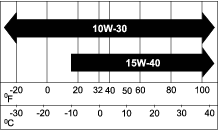
Engine-Oil Specifications
Oil Type: Detergent diesel engine oil (API service CH-4, CI-4, or higher)
Crankcase Capacity: with filter, 3.2 L (0.84 US gallons)
Viscosity: See the table below.
Checking the Engine-Oil Level
-
Park the machine on a level surface, engage the parking brake, and lower the loader arms.
-
Shut off the engine, remove the key, and allow the engine to cool.
-
Open the rear-access cover.
-
Clean the area around the oil dipstick (Figure 28).
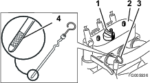
-
Pull out the dipstick and wipe the metal end clean (Figure 28).
-
Slide the dipstick fully into the dipstick tube (Figure 28).
-
Pull the dipstick out and look at the metal end.
Note: The oil level should be within the crosshatched area on the dipstick.
-
If the oil level is low, clean the area around the oil-fill cap and remove the cap (Figure 28).
-
Slowly pour oil into the valve cover. Check the oil level again and ensure that the level is at the top of the crosshatched area on the dipstick.
Note: Use diesel engine oil, API service CH-4, CI-4, or higher; refer to Engine-Oil Specifications.
Important: Do not overfill the crankcase with oil because it may damage the engine.
-
Replace the fill cap and dipstick.
-
Close the rear-access cover.
Changing the Engine Oil and Filter
-
Start the engine and let it run for 5 minutes.
Note: This warms the oil so that it drains better.
-
Park the machine so that the drain side is slightly lower than the opposite side to ensure that the oil drains completely.
-
Lower the loader arms, engage the parking brake, shut off the engine, and remove the key.
-
Place a pan under the oil-drain tube (Figure 29).
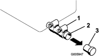
-
Loosen the clamp and remove the plug (Figure 29).
-
When the oil has drained completely, replace the plug and tighten the clamp.
Note: Dispose of the used oil at a certified recycling center.
-
Open the rear-access cover.
-
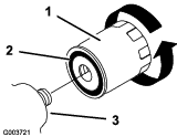
Remove the old filter and wipe the filter adapter (Figure 30) gasket surface.
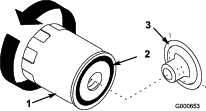
-
Apply a thin coat of new oil to the rubber gasket on the replacement filter (Figure 30).
-
Install the replacement oil filter to the filter adapter. Turn the oil filter clockwise until the rubber gasket contacts the filter adapter, then tighten the filter an additional 1/2 turn (Figure 30).
-
Remove the fill cap (Figure 28) and slowly pour approximately 80% of the specified amount of oil in through the valve cover.
-
Check the oil level.
-
Slowly add additional oil to bring the level to the upper mark on the dipstick.
-
Replace the fill cap.
-
Start the engine and let it run for 15 seconds to allow the filter to fill with oil.
-
Park the machine on a level surface, shut off the engine, and remove the key.
-
Check the engine-oil level. Add oil if needed.
-
Close the rear-access cover.
Fuel System Maintenance
Danger
In certain conditions, fuel is extremely flammable and highly explosive. A fire or explosion from fuel can burn you and others and can damage property.
-
Drain fuel from the fuel tanks when the engine is cold. Do this outdoors in an open area. Wipe up any fuel that spills.
-
Never smoke when draining fuel, and stay away from an open flame or where a spark may ignite the fumes.
-
Refer to Fuel Safety for a complete list of fuel related precautions.
Draining Water from the Fuel Filter
| Maintenance Service Interval | Maintenance Procedure |
|---|---|
| Before each use or daily |
|
-
Park the machine on a level surface, engage the parking brake, and lower the loader arms.
-
Shut off the engine and remove the key.
-
Open the rear-access cover.
-
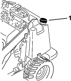
Turn the drain valve until the water runs out of the filter (Figure 31).
Note: The fuel filter is located near the bottom of the fuel tank.
-
Close the valve.
-
Close the rear-access cover.
Changing the Fuel Filter
| Maintenance Service Interval | Maintenance Procedure |
|---|---|
| Yearly |
|
Important: Never install a dirty filter.
-
Park the machine on a level surface, engage the parking brake, and lower the loader arms.
-
Shut off the engine and remove the key.
-
Shut off the fuel valve on the bottom of the fuel tank (Figure 34).
-
Open the rear-access cover.
-
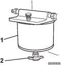
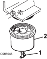
Open the drain valve (Figure 32) and drain the fuel from the fuel filter into a suitable container and dispose of it properly.
-
Remove the fuel filter with a filter wrench (Figure 32).
-
Clean the mounting surface.
-
Lubricate the gasket on the new filter with clean engine oil.
-
Screw on the new filter by hand until the gasket contacts the housing, then tighten it another 1/2 turn.
-
Open the fuel valve on the bottom of the fuel tank (Figure 34).
-
Bleed the fuel system; refer to Bleeding the Fuel System.
-
Start the engine and check for leaks.
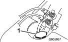
Bleeding the Fuel System
Bleed the air from the fuel system in any of the following situations:
-
Initial start-up of a new machine or a machine that has been stored
-
After the engine has ceased running due to lack of fuel
-
After maintenance has been performed on the fuel system components
-
Park the machine on a level surface, engage the parking brake, and lower the loader arms.
-
Shut off the engine and remove the key.
-
Open the rear-access cover.
-
Place a drain pan under the fuel filter to catch fuel spills.
-
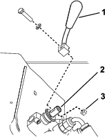
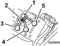
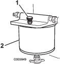
Open the bleed screw on top of the fuel filter to fill the bowl with fuel (Figure 33).
-
Close the bleed screw when fuel comes out in a steady stream.
-
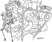
On left side of the engine, locate the air vent plug on top of the fuel-injection pump and connect a hose to it, leading to a drain pan.
-
Open the vent plug and crank the engine until fuel comes out a steady stream.
-
Close the vent plug.
-
Close the rear-access cover.
Draining the Fuel Tank
-
Park the machine on a level surface, engage the parking brake, and lower the loader arms.
-
Shut off the engine and remove the key.
-
Shut off the fuel valve in the hose near the bottom of the fuel tank (Figure 34).
-
Open the rear-access cover.
-
Loosen the hose clamp at the fuel filter and slide it up the fuel line away from the filter.
-
Pull the fuel line off the fuel filter, open the fuel valve, and allow the fuel to drain into a fuel can or drain pan.
-
Close the fuel valve.
-
Install the fuel line onto the fuel filter.
-
Slide the hose clamp close to the fuel filter to secure the fuel line.
-
Close the rear-access cover.
-
Open the fuel valve in the hose near the bottom of the fuel tank as illustrated in Figure 34.
Note: Now is the best time to install a new fuel filter because the fuel tank is empty.
Electrical System Maintenance
Electrical System Safety
-
Disconnect the battery before repairing the machine. Disconnect the negative terminal first and the positive last. Connect the positive terminal first and the negative last.
-
Charge the battery in an open, well-ventilated area, away from sparks and flames. Unplug the charger before connecting or disconnecting the battery. Wear protective clothing and use insulated tools.
-
Battery acid is poisonous and can cause burns. Avoid contact with skin, eyes, and clothing. Protect your face, eyes, and clothing when working with a battery.
-
Battery gases can explode. Keep cigarettes, sparks, and flames away from the battery.
Servicing the Battery
| Maintenance Service Interval | Maintenance Procedure |
|---|---|
| Every 75 hours |
|
Always keep the battery clean and fully charged. Use a paper towel to clean the battery case. If the battery terminals are corroded, clean them with a solution of 4 parts water and 1 part baking soda. Apply a light coating of grease to the battery terminals to reduce corrosion.
Specifications: 12 V, 450 A (cold cranking)
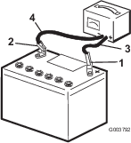
Removing the Battery
-
Park the machine on a level surface, engage the parking brake, and lower the loader arms.
-
Shut off the engine and remove the key.
-
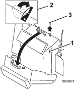
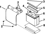
Remove the battery cover (Figure 35)
-
Remove the nuts and bars securing the battery (Figure 35).
-
Disconnect the negative (black) cable to the negative (-) battery post (Figure 35).
-
Disconnect the positive (red) cable to the positive (+) battery post (Figure 35).
-
Lift the battery off the platform.
Charging the Battery
Important: Always keep the battery fully charged (1.265 specific gravity). This is especially important to prevent battery damage when the temperature is below 0°C (32°F).
-
Remove the battery from the machine; refer to Removing the Battery.
-
Charge the battery for 10 to 15 minutes at 25 to 30 A or 30 minutes at 4 to 6 A (Figure 36). Do not overcharge the battery.
-
When the battery is fully charged, unplug the charger from the electrical outlet, then disconnect the charger leads from the battery posts (Figure 36).
Cleaning the Battery
Note: Keep the terminals and the entire battery case clean, to help extend battery life.
-
Park the machine on a level surface, engage the parking brake (if equipped), and lower the loader arms.
-
Shut off the engine and remove the key.
-
Remove the battery from the machine; Removing the Battery.
-
Wash the entire case with a solution of baking soda and water.
-
Rinse the battery with clear water.
-
Coat the battery posts and cable connectors with Grafo 112X (skin-over) grease (Toro Part No. 505-47) or petroleum jelly to prevent corrosion.
-
Install the battery; refer to Installing the Battery.
Installing the Battery
-
Install the battery onto the platform (Figure 35).
-
Secure the battery in the chassis with the bars and nuts removed previously (Figure 35).
-
Using the fasteners previously removed, install the positive (red) battery cable to the positive (+) battery terminal (Figure 35).
-
Slide the red terminal boot onto the positive battery post.
-
Using the fasteners previously removed, install the negative (black) battery cable to the negative (-) battery terminal (Figure 35).
-
Install the battery cover (Figure 35).
Important: Ensure that the battery cables do not contact any sharp edges or each other.
Servicing a Replacement Battery
The original battery is maintenance-free and does not require service. For servicing a replacement battery, refer to the battery manufacturer’s instructions.
Drive System Maintenance
Checking the Tire Pressure
| Maintenance Service Interval | Maintenance Procedure |
|---|---|
| Before each use or daily |
|
Maintain the air pressure in the tires as specified. Check the tires when they are cold to get the most accurate reading.
Pressure: 103 to 138 kPa (15 to 20 psi)
Note: Use a lower tire pressure, 103 kPa (15 psi), when operating in sandy soil conditions to provide better traction in the loose soil.
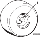
Checking the Wheel-Lug Nuts
| Maintenance Service Interval | Maintenance Procedure |
|---|---|
| After the first 8 hours |
|
| Every 100 hours |
|
Check and torque the wheel lug nuts to 68 N∙m (50 ft-lb).
Cooling System Maintenance
Cooling System Safety
-
Swallowing engine coolant can cause poisoning; keep out of reach from children and pets.
-
Discharge of hot, pressurized coolant or touching a hot radiator and surrounding parts can cause severe burns.
-
Always allow the engine to cool at least 15 minutes before removing the radiator cap.
-
Use a rag when opening the radiator cap, and open the cap slowly to allow steam to escape.
-
Cleaning the Radiator Screen
| Maintenance Service Interval | Maintenance Procedure |
|---|---|
| Before each use or daily |
|
Remove any buildup of grass, dirt or other debris from the radiator screen with compressed air.
Checking the Engine-Coolant Level
| Maintenance Service Interval | Maintenance Procedure |
|---|---|
| Before each use or daily |
|
The cooling system is filled with a 50/50 solution of water and permanent ethylene glycol antifreeze. Check the level of coolant at the beginning of each day, before starting the engine.
Danger
The rotating shaft and fan can cause personal injury.
-
Do not operate the machine without the covers in place.
-
Keep your fingers, hands, and clothing clear of the rotating fan and drive shaft.
-
Park the machine on a level surface, lower the loader arms, engage the parking brake, shut off the engine, and remove the key from the key switch before performing maintenance.
-
Park the machine on a level surface, lower the loader arms, engage the parking brake, and shut off the engine.
-
Remove the key from the key switch and allow the engine to cool.
-
Remove the radiator cap and check the coolant level (Figure 38).
The coolant should be up to the filler neck.
-
If the coolant level is low, add coolant up to the bottom of the filler neck.
Important: Do not overfill the radiator.
-
Replace the radiator cap, ensuring that it is tightly sealed.
Changing the Engine Coolant
| Maintenance Service Interval | Maintenance Procedure |
|---|---|
| Yearly |
|
Have an Authorized Service Dealer change the engine coolant yearly.
If you need to add engine coolant, refer to Checking the Engine-Coolant Level.
Brake Maintenance
Testing the Parking Brake
| Maintenance Service Interval | Maintenance Procedure |
|---|---|
| Before each use or daily |
|
-
Engage the parking-brake; refer to Parking-Brake Lever.
-
Start the engine.
-
Slowly attempt to drive the machine forward or rearward.
-
If the machine moves, contact your Authorized Service Dealer for service.
Hydraulic System Maintenance
Hydraulic System Safety
-
Seek immediate medical attention if fluid is injected into skin. Injected fluid must be surgically removed within a few hours by a doctor.
-
Ensure that all hydraulic-fluid hoses and lines are in good condition and all hydraulic connections and fittings are tight before applying pressure to the hydraulic system.
-
Keep your body and hands away from pinhole leaks or nozzles that eject high-pressure hydraulic fluid.
-
Use cardboard or paper to find hydraulic leaks.
-
Safely relieve all pressure in the hydraulic system before performing any work on the hydraulic system.
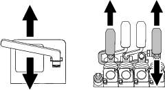
Relieving Hydraulic Pressure
To relieve hydraulic pressure while the engine is on, disengage the auxiliary hydraulics and fully lower the loader arms.
To relieve the pressure while the engine is off, move the auxiliary-hydraulics lever between the forward and reverse flow positions to relieve auxiliary hydraulic pressure, move the attachment-tilt lever forward and rearward, and move the loader-arm lever forward to lower the loader arms (Figure 39).
Hydraulic Fluid Specifications
| Maintenance Service Interval | Maintenance Procedure |
|---|---|
| Every 25 hours |
|
| Every 1,500 hours |
|
Hydraulic Tank Capacity: 56 L (14.8 US gallons)
Use only 1 of the following fluids in the hydraulic system:
-
Toro Premium Transmission/Hydraulic Tractor Fluid (refer to your Authorized Service Dealer for more information)
-
Toro PX Extended Life Hydraulic Fluid (refer to your Authorized Service Dealer for more information)
-
If either of the above Toro fluids are not available, you may use another Universal Tractor Hydraulic Fluid (UTHF), but they must be only conventional, petroleum-based products. The specifications must fall within the listed range for all the following material properties and the fluid should meet the listed industry standards. Check with your hydraulic fluid supplier to determine if the fluid meets these specifications.
Note: Toro will not assume responsibility for damage caused by improper substitutions, so use only products from reputable manufacturers who will stand behind their recommendations.
Material Properties Viscosity, ASTM D445 cSt at 40°C: 55 to 62 cSt at 100°C: 9.1 to 9.8 Viscosity index, ASTM D2270 140 to 152 Pour Point, ASTM D97 -43 to -37°C (-46 to -35°F) Industry Standards API GL-4, AGCO Powerfluid 821 XL, Ford New Holland FNHA-2-C-201.00, Kubota UDT, John Deere J20C, Vickers 35VQ25 and Volvo WB-101/BM Note: Many hydraulic fluids are almost colorless, making it difficult to spot leaks. A red dye additive for the hydraulic system fluid is available in 20 ml (0.67 fl oz) bottles. One bottle is sufficient for 15 to 22 L (4 to 6 US gallons) of hydraulic fluid. Order Part No. 44-2500 from your Authorized Service Dealer.
Checking the Hydraulic-Fluid Level
| Maintenance Service Interval | Maintenance Procedure |
|---|---|
| Every 25 hours |
|
Check the hydraulic-fluid level before the engine is first started and after every 25 operating hours.
Refer to Hydraulic Fluid Specifications.
Important: Always use the correct hydraulic fluid. Unspecified fluids will damage the hydraulic system.
-
Park the machine on a level surface, remove any attachment, engage the parking brake (if equipped), raise the loader arms, and install the cylinder locks.
-
Shut off the engine, remove the key, and allow the engine to cool.
-
Remove the hood/front access cover.
-
Clean the area around the filler neck of the hydraulic tank (Figure 40).
-
Remove the filler-neck cap and check the fluid level on the dipstick (Figure 40).
The fluid level should be between the marks on the dipstick.
-
If the level is low, add enough fluid to raise it to the proper level.
-
Install the filler-neck cap.
-
Install the hood/front access cover.
-
Remove and store the cylinder locks and lower the loader arms.
Replacing the Hydraulic Filter
| Maintenance Service Interval | Maintenance Procedure |
|---|---|
| After the first 8 hours |
|
| Every 400 hours |
|
Important: Do not substitute an automotive oil filter; otherwise, severe hydraulic system damage may result.
-
Park the machine on a level surface, remove any attachment, engage the parking brake (if equipped), raise the loader arms, and install the cylinder locks.
-
Shut off the engine and remove the key.
-
Remove the hood/front access cover.
-
Place a drain pan under the filter.
-
Remove the old filter (Figure 41) and wipe the surface of the filter adapter clean.
-
Apply a thin coat hydraulic fluid to the rubber gasket on the replacement filter (Figure 41).
-
Install the replacement hydraulic filter onto the filter adapter (Figure 41). Tighten it clockwise until the rubber gasket contacts the filter adapter, then tighten the filter an additional 1/2 turn.
-
Clean up any spilled fluid.
-
Start the engine and let it run for about 2 minutes to purge air from the system.
-
Shut off the engine and check for leaks.
-
Check the fluid level in the hydraulic tank; refer to Checking the Hydraulic-Fluid Level. Add fluid to raise the level to mark on dipstick. Do not overfill the tank.
-
Install the hood/front access cover.
-
Remove and store the cylinder locks and lower the loader arms.
Changing the Hydraulic Fluid
| Maintenance Service Interval | Maintenance Procedure |
|---|---|
| Yearly |
|
-
Park the machine on a level surface, remove any attachment, engage the parking brake (if equipped), raise the loader arms, and install the cylinder locks.
-
Shut off the engine and remove the key.
-
Remove the hood/front-access cover.
-
Place a large drain pan under the machine that can hold at least 61 L (16 US gallons).
-
Remove the drain plug from the bottom of the hydraulic tank and allow the fluid to completely drain out.
-
Install the drain plug.
-
Fill the hydraulic tank with hydraulic fluid; refer to Hydraulic Fluid Specifications.
Note: Dispose of used oil at a certified recycling center.
-
Install the hood/front-access cover.
-
Remove and store the cylinder locks and lower the loader arms.
Cleaning
Removing Debris
| Maintenance Service Interval | Maintenance Procedure |
|---|---|
| Before each use or daily |
|
Important: Operating the engine with blocked screens and/or cooling shrouds removed will result in engine damage due to overheating.
-
Park the machine on a level surface, raise the loader arms, and install the cylinder locks.
-
Shut off the engine and remove the key.
-
Remove the front-access cover.
-
Clean any debris from the grill.
-
Open the rear-access cover.
-
Wipe away debris from the air cleaner.
-
Clean any debris buildup on the engine with a brush or blower.
Important: Blow the dirt out rather than wash it out. If you use water, keep it away from electrical items and hydraulic valves. Do not use a high-pressure washer. High-pressure washing can damage the electrical system and hydraulic valves or deplete grease.
-
Replace and secure the front and rear-access covers.
-
Remove and store the cylinder locks and lower the loader arms.