Introduction

This machine is a tow-behind attachment intended to be used by professional, hired operators in commercial applications. It is a renovation machine used for cutting, scarifying or removing large areas of grass and leaving behind a clean surface. Using this product for purposes other than its intended use could prove dangerous to you and bystanders.

Read this information carefully to learn how to operate and maintain your product properly and to avoid injury and product damage. You are responsible for operating the product properly and safely.

Visit www.Toro.com/Bullseye for product safety and operation training materials, accessory information, help finding a dealer, or to register your product.

Whenever you need service, genuine Bullseye parts, or additional information, contact an Authorized Service Dealer or Bullseye Customer Service and have the model and serial numbers of your product ready. Figure 1 identifies the location of the model and serial numbers on the product. Write the numbers in the space provided.

Important: With your mobile device, you can scan the QR code on the serial-number decal (if equipped) to access warranty, parts, and other product information.

g346864

This manual identifies potential hazards and has safety messages identified by the safety-alert symbol (Figure 2), which signals a hazard that may cause serious injury or death if you do not follow the recommended precautions.

g000502

This manual uses 2 words to highlight information. Important calls attention to special mechanical information and Note emphasizes general information worthy of special attention.

Warning

CALIFORNIA

Proposition 65 Warning

Use of this product may cause exposure to chemicals known to the State of California to cause cancer, birth defects, or other reproductive harm.

Safety

General Safety

This product is capable of causing personal injury. Always follow all safety instructions to avoid serious personal injury.

  • Read and understand the contents of both this Operator’s Manual and the operator’s manual of the traction unit before using this machine. Ensure that everyone using this product knows how to use this machine and the traction unit and understands the warnings.

  • Use your full attention while operating the machine. Do not engage in any activity that causes distractions; otherwise, injury or property damage may occur.

  • Do not put your hands or feet near moving components of the machine.

  • Do not operate the machine without all guards and other safety protective devices in place and working on the machine.

  • Keep the machine away from bystanders while it is moving.

  • Keep children out of the operating area. Never allow children to operate the machine.

  • Stop the machine, shut off the engine, engage the parking brake of the traction unit, remove the key, and wait for all moving parts to stop before servicing, fueling, or unclogging the machine.

Improperly using or maintaining this machine can result in injury. To reduce the potential for injury, comply with these safety instructions and always pay attention to the safety-alert symbol Graphic, which means 
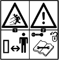
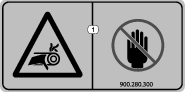
Caution, Warning, or Danger—personal safety instruction. Failure to comply with these instructions may result in personal injury or death.

Safety and Instructional Decals

Graphic

Safety decals and instructions are easily visible to the operator and are located near any area of potential danger. Replace any decal that is damaged or missing.

decal105-0698
decal119-6807
decal133-8061
decal144-7905
decal144-7906
decal144-7910
decal144-7911
decal144-8256
decal144-8338
decal144-8339

Setup

Removing the Machine from the Pallet

The attachment is shipped vertically on the pallet. Perform the following instructions to remove it from the pallet.

Danger

The attachment is unstable and could swing when lifted, injuring anyone beneath it or around it.

  • Refer to the lifting machine operator’s manual to ensure that it is rated to lift the attachment.

  • Ensure the lift height is kept to a minimum and only high enough to remove the shipping material.

  • Do not crawl under the attachment.

The machine is shipped vertically on the pallet. Use the following instructions to remove it from the pallet.

Note: Use 2 different machines at the same time to lift the machine and set it in operating position.

  1. Place the pallet on level ground.

  2. Mount lifting cables at the lifting points shown in Figure 3 and Figure 4.

    Note: Refer to the lifting machine Operator's Manual to ensure that it is rated to lift the attachment.

  3. Raise the attachment (including the pallet) 50 mm (2 inches) from the ground.

  4. Gently lower the attachment in a controlled way as shown in Figure 4 until it is placed on the ground.

  5. Remove the hitch pins.

  6. Remove the pallet.

  7. Install the hitch pins.

    g357840
    g348382

Inspecting the Machine

Checking the Grease and Gearbox

Check and ensure that the gearbox has fluid; refer to Checking the Gearbox Lubrication.

Ensure that the machine is greased before use; refer to Greasing the Attachment.

Checking the Traction Unit Requirements

Use the following figure and list as a reference:

  • Refer to the specifications section for the minimum horse power, maximum horse power, and the minimum lifting capacity; Specifications.

  • The traction unit must have a category II or III 3-point hitch.

  • The traction unit must have a PTO output-shaft speed of 540 rpm.

  • Adequate front-end weight (ballast) to offset the weight of the machine.

  • Check the tire air pressure of the traction unit.

    Adjust the tire air pressure as needed.

    Important: Do not exceed the maximum or minimum tire inflation pressures as recommended by tire manufacturer.

    g007332

Checking the Ballast Requirements

Warning

Mounting the machine to the rear of the traction unit decreases the weight on its front axle.

Failure to add required ballast may result in an accident and severe injury or death.

  • To ensure adequate steering control and stability you may need to add ballast to the front of the traction unit.

  • Refer to the traction unit operator's manual for ballast requirements.

Product Overview

g348670
g348669

Note: Specifications and design are subject to change without notice.

Traction Unit Requirements

Tractor horse power40 to 50 hp
Minimum lifting capacity (61 cm (24 inches) from lower link pins)1650 kg (3640 lb)
3-point hitchCategory 2 or higher
Hydraulic connections2 double-operating valves

Attachment Specifications

Weight1319 kg (2908 lbs)
Length183 cm (72 inches)
Height114.3 cm (45 inches)
Conveyor heightUp to 170.2 cm (67 inches)
Working width2 m (79 inches)
Working depth0 to 50 mm (0 to 2 inches)
Maximum working speed3 km/h (1.8 mph)
PTO output-shaft speed540 rpm

Attachments/Accessories

A selection of Bullseye approved attachments and accessories may be available for use with the machine to enhance and expand its capabilities. Contact your Authorized Service Dealer or authorized Bullseye distributor or go to www.Toro.com/Bullseye for a list of all approved attachments and accessories.

To ensure optimum performance and continued safety certification of the machine, use only genuine Bullseye replacement parts and accessories. Replacement parts and accessories made by other manufacturers could be dangerous, and such use could void the product warranty.

Operation

Note: Determine the left and right sides of the machine from the normal operating position.

Before Operation

Before Operation Safety

  • Never allow children or untrained people to operate or service the machine. Local regulations may restrict the age of the operator. The owner is responsible for training all operators and mechanics.

  • Keep your hands clear of the joint pivot areas when handling the PTO driveshaft.

  • Do not step on, over, or under the PTO or driveshafts.

  • Become familiar with the safe operation of the equipment, operator controls, and safety signs.

  • Know how to stop the machine and shut off the engine of the traction unit quickly.

  • Do not use PTO spline adapters or extensions.

  • Ensure that the guards and shields are properly installed and maintained. Replace missing, damaged, or worn guards and shields before using the machine.

  • Ensure that the PTO driveshaft does not contact the drawbar.

  • Inspect the area where you will use the machine and remove all objects that the machine could strike.

  • Ensure that your traction unit is suitable for use with an implement of this weight by checking with your traction unit supplier or manufacturer.

  • Shut off the machine, shut off the engine and remove the key of the traction unit, and wait for all moving parts to stop before making any adjustments to the machine.

Understanding the Traction Unit Controls

Familiarize yourself with the operation of the following traction unit controls before operating the machine:

  • PTO engagement

  • 3 point hitch (raise/lower)

  • Clutch

  • Throttle

  • Gear selection

  • Parking brake

    Important: Refer to the traction unit operator's manual for operating instructions.

Practicing the Operating Procedures

Before using the machine, find a clear area and practice operating the traction unit with the machine installed.

Important: If there are sprinkler heads, electrical or communication lines, or other obstructions in the area being scarified or renovated, mark these locations to ensure that these items are not damaged during operation.

  • Operate the traction unit using the recommended gear settings and PTO drive speeds and become thoroughly familiar with the traction unit handling with the attached machine.

  • Practice stopping and starting, raising the machine, and lowering the machine, disengaging the PTO drive, and aligning the machine with previous passes.

Practice sessions helps you gain confidence in the performance of the machine and helps ensure that you are using it properly.

Warning

Adjusting or maintaining the machine while the traction unit is running may result in an accident and severe injury or death.

  • Lower the machine onto the ground or jacks stands while repairing the machine.

  • Before leaving the operator’s seat, disengage the PTO drive, engage the parking brake, shut off the engine, remove the key, and wait for all moving parts to stop.

  • Ensure that all safety devices are secured and in proper position before resuming operation.

Connecting to a 3-Point Hitch

Connecting the Lower Link Arms

  1. Ensure that the attachment is positioned on a level surface.

  2. Remove the hairpin cotters from the hitch pins (Figure 8).

    g347982
  3. Back the traction unit squarely up to the attachment so that you can attach the lower connecting arms to the frame.

  4. Engage the parking brake, shut off the engine, and remove the key from the ignition. Wait for the engine and all moving parts to stop before leaving the operator's seat.

    Note: For maximum ground clearance, install the hitch pins in the lower mounting holes of the hitch plate for the attachment.

  5. Insert the right and left lower link arms onto the hitch pins (Figure 9).

    g347981
  6. Secure the lower link arms to the hitch pins using the hairpin cotters.

Connecting the Upper Link Arm

  1. Connect the upper link arm to the bracket and secure it with the link pin and the hairpin cotter (Figure 10).

    Note: Use the slotted hole if you want the attachment to follow the terrain during operation.

    g347998
  2. Grease the threaded steel upper link arm tubes.

  3. Rotate the upper link arm to shorten the link. Adjust it until the attachment is flat on the ground.

  4. Tighten the jam nut to secure the upper link arm into position.

  5. Start the traction unit and lift the attachment off the ground.

Connecting the PTO Driveshaft

Adjusting the PTO Driveshaft Length

Adjust the length of the PTO driveshaft whenever you install the attachment to a different traction unit.

Important: If the length of PTO is not adjusted properly, using the attachment can damage the traction unit or the attachment. The overlapping length of the cylinders must be at least 150 mm (6 inches). The length changes when you lift or install the attachment on a different traction unit.

  1. Park the machine on a level surface, engage the parking brake, and lower the attachment to the ground.

  2. Shut off the engine and remove the key.

  3. Pull the PTO driveshaft sections apart (Figure 11).

    g347461
  4. Assemble the outer PTO driveshaft section to the traction-unit PTO output shaft (Figure 12).

    Note: Pull on the driveshaft to ensure that the locking pin engages the PTO output shaft.

    g007328
  5. Hold the driveshaft sections parallel to each other to determine if they are too long (Figure 13).

    Note: Each driveshaft section must be 76 mm (3 inches) from the U-joint (Figure 13).

  6. If the driveshaft sections are too long, mark 76 mm (3 inches) back from U-joint on each section (Figure 13).

    g347524
  7. Remove and cut each section at the mark (Figure 14).

    Note: Ensure the same amount is removed from each section.

    g347473
  8. Deburr the ends of the sections (Figure 15).

    g347459
  9. Assemble the outer PTO driveshaft section to the PTO shaft of the traction unit (Figure 12).

  10. Raise the attachment to the position where the traction-unit PTO output shaft and gearbox input shaft are furthest apart (Figure 16).

  11. Hold the driveshaft sections parallel to each other and check to ensure that they overlap 150 mm (6 inches) or more (Figure 16).

    Note: If the sections do not overlap 150 mm (6 inches), contact your authorized distributor.

    g347621
  12. Grease and assemble the sections.

    Important: Do not use the attachment if the PTO driveshaft is damaged; replace the damaged driveshaft before operation.

Installing the PTO Driveshaft

Important: Refer to the PTO driveshaft owner’s manual for additional operating and safety information.

Caution

Operating the machine without the PTO guards and shields may cause injury or death.

Keep all PTO guards and shields in place.

Important: When connecting the PTO, ensure that the attachment is not lifted higher than necessary. Lifting the attachment too high causes the PTO driveshaft knuckles to break (Figure 17). The PTO can operate up to an angle of 25°, but operating it beyond 30° angle may severely damage the shaft.

Note: Ensure the cross bearings are aligned as shown in Figure 23.

g345626
  1. Assemble the PTO driveshaft to the gearbox input shaft of the attachment.

    g345541
  2. Assemble the PTO driveshaft to the PTO output shaft of the traction unit.

    g007328
  3. Slide the PTO driveshaft forward as far as the PTO output shaft allows.

  4. Pull back on the locking collar of the PTO shaft coupler to secure the PTO driveshaft. Slide the PTO driveshaft back and forth to ensure that it is locked securely.

  5. Verify that the telescoping tube has a minimum of 150 mm (6 inches) overlap when the attachment is raised to the maximum height.

    g345507

Connecting the Hydraulic Hoses

  1. Connect the hydraulic hoses from the attachment to the traction unit. Ensure the hydraulic hoses are engaged in the ports.

  2. Confirm that the traction unit levers operate the attachment hydraulics.

Adjusting the Working Depth

Adjusting the Fraise Depth

The working depth is set by adjusting the front roller.

Ensure the rear roller is set to the fraising slot shown in Figure 21.

Important: Adjust the working depth only when the traction unit is parked, the parking brake is engaged, the PTO is disengaged, and the engine is shut off.

  1. Loosen the jam nut on the top of each rear link.

  2. Adjust the rear links until they align with the frasing slot in the gauge (Figure 21).

  3. Tighten the jam nut for each rear link (Figure 21).

    g348674
  4. Using the adjustment handles, adjust the front links to your desired depth by using the indicators on both sides.

  5. Check the working depth by running the machine a few meters (yards). Refer to Operating the Attachment.

  6. If needed, adjust the front links until you reach your desired depth.

    Note: When the lift conveyor is folded out, the machine weight shifts to this side. Due to the extra weight, you can remove more material on this side. To compensate for this extra weight, adjust the front and back links on the right side (lift conveyor side).

    g348709

Adjusting the Scarifying Depth

The working depth is set by adjusting the front roller.

Ensure the rear roller is set to the scarifying slot shown in Figure 21.

Important: Adjust the working depth only when the traction unit is parked, the parking brake is engaged, the PTO is disengaged, and the engine is shut off.

  1. Loosen the jam nut on the top of each rear link.

  2. Adjust the rear links until they align with the scarifying slot in the gauge (Figure 21).

  3. Tighten the jam nut for each rear link (Figure 21).

  4. Using the adjustment handles, adjust the front links to your desired depth by using the indicators on both sides (Figure 22).

  5. Check the working depth by running the machine a few meters (yards). Refer to Operating the Attachment.

  6. If needed, adjust the front links until you reach your desired depth.

    Note: When the lift conveyor is folded out, the machine weight shifts to this side. Due to the extra weight, you can remove more material on this side. To compensate for this extra weight, adjust the front and back links on the right side (lift conveyor side).

Transporting the Machine

To prevent losing control of the machine, move slowly across steep inclines and approach rough, undulating areas slowly and carefully.

Important: Do not exceed 12 km/h (7.5 mph) while transporting the attachment.

  1. Park the traction unit and machine on a level surface, disengage the PTO, engage the parking brake, shut off the engine, remove the key, and wait for all moving parts to stop before leaving the operator's seat.

  2. Move the lift conveyor to the transport position.

  3. Raise the attachment and drive the traction unit, not exceeding 12 km/h (7.5 mph).

During Operation

During Operation Safety

  • The owner/operator can prevent and is responsible for accidents that may cause personal injury or property damage.

  • Wear appropriate clothing, including eye protection; long pants; substantial, slip-resistant footwear; and hearing protection. Tie back long hair and do not wear loose clothing or loose jewelry.

  • Use your full attention while operating the machine. Do not engage in any activity that causes distractions; otherwise, injury or property damage may occur.

  • Do not operate the machine when tired, ill, or under the influence of alcohol or drugs.

  • Never carry passengers on the machine and keep bystanders and pets away from the machine during operation.

  • Operate the machine only in good visibility to avoid holes or hidden hazards.

  • Before you start the engine, ensure that all drives are in neutral, the PTO is disengaged, the parking brake is engaged, and you are in the operating position.

  • Keep your hands and feet away from moving parts.

  • Look behind and down before backing up to be sure of a clear path.

  • Use care when approaching blind corners, shrubs, trees, or other objects that may obscure your vision.

  • Do not run the PTO with the attachment raised.

  • Stop the attachment whenever you are not using it.

  • Stop the machine, shut off the engine, remove the key, wait for all moving parts to stop, and inspect the machine after striking an object or if there is an abnormal vibration in the machine. Make all necessary repairs before resuming operation.

  • Slow down and use caution when making turns and crossing roads and sidewalks with the machine. Always yield the right-of-way.

  • Reduce speed on rough roads and surfaces.

  • When attached to a traction unit, and in the raised position, the weight of the attachment affects stability, braking and steering. Exercise caution when transporting between working areas.

  • Never leave a running machine unattended.

  • Before leaving the operating position, do the following:

    • Ensure that the PTO is disengaged.

    • Park the machine on a level surface.

    • Engage the parking brake.

    • Lower the attachment.

    • Shut off the engine and remove the key.

    • Wait for all moving parts to stop before leaving the machine.

  • Do not operate the machine when there is the risk of lightning.

  • Use Bullseye accessories, attachments, and replacement parts only.

  • For disassembly or repair of all steel PTO driveshaft parts (tubes, bearings, joints, etc.), contact your authorized distributor. Removing components for repairs and assembly may damage some parts if not performed with special tools by trained technicians.

  • Do not operate the attachment if the PTO or driveshaft guards are missing.

  • Be careful when turning the machine so that the traction unit tires do not contact the PTO driveshaft.

  • Secure hydraulic hoses, electrical wiring, ropes, and other items to keep them from contacting the PTO driveshaft guard.

Slope Safety

  • Review the traction unit specifications to ensure that you do not exceed its slope capabilities.

  • Slopes are a major factor related to loss of control and rollover accidents, which can result in severe injury or death. You are responsible for safe slope operation. Operating the machine on any slope requires extra caution.

  • Review and understand the slope instructions in the manual and on the traction unit.

  • Evaluate the site conditions to determine if the slope is safe for machine operation, including surveying the site. Always use common sense and good judgment when performing this survey.

  • Review the slope instructions listed below for operating the machine on slopes and to determine whether you can operate the machine in the conditions on that day and at that site. Changes in the terrain can result in a change in slope operation for the machine.

  • Avoid starting, stopping, or turning the machine on slopes. Avoid making sudden changes in speed or direction. Make turns slowly and gradually.

  • Do not operate a machine under any conditions where traction, steering, or stability are in question.

  • Remove or mark obstructions such as ditches, holes, ruts, bumps, rocks, or other hidden hazards. Tall grass can hide obstructions. Uneven terrain could overturn the machine.

  • Be aware that operating the machine on wet grass, across slopes, or downhill may cause the machine to lose traction. Loss of traction to the drive wheels may result in sliding and a loss of braking and steering.

  • Use extreme caution when operating the machine near drop-offs, ditches, embankments, water hazards, or other hazards. The machine could suddenly roll over if a wheel goes over the edge or the edge caves in. Establish a safety area between the machine and any hazard.

  • Identify hazards at the base of the slope. If there are hazards, mow the slope with a power walk-behind mower.

  • If possible, keep the attachment lowered to the ground while operating on slopes. Raising the attachment while operating on slopes can cause the machine to become unstable.

  • Use extreme caution with other attachments. These can change the stability of the machine and cause a loss of control. Always keep the machine in gear when going down slopes. Do not coast downhill (applicable only to gear-drive units).

Operating the Attachment

Using the PTO

Before engaging the PTO, verify the following:

  • The angle of the pivot pins are 25° or less and never exceeding 30°.

  • The pivot pins are aligned.

  • The overlap of the PTO cylinders is at least 150 mm (6 inches).

  • The PTO protection guard is not damaged.

Starting the Attachment

Warning

Lifting the attachment too high causes the PTO driveshaft knuckles to break.

Ensure that the attachment is not lifted higher than is necessary.

Important: The PTO can operate up to an angle of 25°, but operating it beyond 30° angle may severely damage the shaft (Figure 23).

g345626
  1. Drive to the location where you will use the attachment

  2. Inspect the area where you will use the machine and remove all objects that the machine could strike.

  3. Locate and mark all electrical or communication lines, irrigation components, and other obstructions in the area.

  4. Park the machine on a level surface and lower the attachment.

  5. Engage the parking brake, shut off the engine, and remove the key from the traction unit.

  6. Adjust the lift conveyor in the desired position.

    Note: Ensure there is enough clearance around the machine where you unfold the conveyor.

  7. Adjust the working depth of the attachment; refer to Adjusting the Working Depth.

  8. Mount the upper link arm in the slotted hole so that the attachment follows the terrain; refer to Connecting the Upper Link Arm.

  9. Start the traction unit and raise the attachment so that the knives do not touch the ground.

    Warning

    The conveyor belts are rotating when removing debris and could cause personal injury.

    • Keep away from moving parts.

    • Keep clear of the discharge opening.

    • Ensure there is clearance for the second machine collecting the debris.

  10. Allow a second machine for collecting the debris to drive under the conveyor.

  11. Engage the traction unit into the proper gear.

  12. Activate the hydraulic valve on the traction unit to engage the horizontal belt and the transport belt.

  13. Lower the attachment until it is approximately 50 mm (2 inches) above the ground.

  14. Engage the traction unit PTO at a low engine speed.

  15. Increase the traction unit PTO speed to approximately 300 rpm.

  16. Drive the traction unit forward slowly and allow the attachment to smoothly lower onto the rollers.

    Note: Ensure the second machine is following to collect the debris.

  17. Slowly lower the attachment until it reaches the working depth.

  18. Drive forward and increase the rotational speed until the PTO driveshaft speed reaches 540 rpm.

  19. Increase the traction unit speed to a maximum of 3 km/h (1.8 mph).

    Important: Ensure the speed of the traction unit does not exceed 3km/h (1.8 mph).

  20. Drive the traction unit and attachment a few meters (yards) and check the working depth. If necessary, adjust the working depth as described in Adjusting the Working Depth.

  21. After operating the attachment, close the hydraulic valve on the traction unit to stop the belts and turn around by raising it to approximately 50 mm (2 inches) above the ground.

    Note: Ensure there is enough clearance around the machine where you turn around.

  22. After turning around, allow the second machine to drive under the conveyor, open the hydraulic valve on the traction unit to start the belts, lower the attachment, and continue operation.

Stopping the Attachment

  1. Decrease the PTO driveshaft speed to approximately 300 rpm by decreasing the engine speed.

  2. Lift the machine slightly off the ground.

  3. Switch the PTO off as soon as the knives no longer touch the soil.

  4. Close the hydraulic valve on the traction unit to stop the belts.

  5. Lift the attachment.

  6. Allow the second machine to move away from the conveyor.

  7. Go to the next work area.

Operating Tips

  • Engage the PTO at low engine speed. Lower the machine and increase engine speed to achieve a PTO speed of 540 rpm (maximum). Operate the engine at a speed that the machine runs most smoothly.

  • Make very gradual turns. Never make sharp turns with the machine lowered. Plan your path before lowering the machine.

  • Do not use the attachment if the ground is too wet.

  • Raise the working depth if the ground is hard packed.

  • Always check/adjust the top link whenever you change the depth. The front of the attachment should be vertical.

  • Look backward frequently to ensure that the machine is operating properly, the second machine for collecting the debris is following, and the alignment is maintained with previous passes.

  • Replace broken knives, and inspect and correct damage to those still usable. Repair any other machine damage before resuming operation.

After Operation

After Operation Safety

  • Park the machine on a level surface; engage the parking brake; shut off the engine; remove the key; and wait for all movement to stop before leaving the machine.

  • Do not step on, over, or under the driveshaft.

  • Do not use the restrain chain of the PTO-shaft guard to support the shaft when transporting or storing the mower.

  • Do not rest the PTO shaft on the ground.

  • Do not allow the PTO-shaft guards to pull apart.

  • Keep all parts of the machine in good working condition and all hardware tightened.

  • Replace all worn, damaged, or missing decals.

Removing the Attachment

  1. Park the machine on a level surface and engage the parking brake.

  2. Lower the front and rear rollers enough to allow the attachment to rest on the rollers without the knives touching the ground. Refer to Adjusting the Working Depth.

  3. Lower the attachment onto the rollers.

  4. Shut off the engine and remove the key from the traction unit.

  5. Remove the hydraulic hoses from the traction unit.

  6. Remove the top link from the attachment.

    g347998
  7. Remove the PTO shaft from the traction unit.

    g007328
  8. Remove the lower links from the attachment.

    Important: Ensure that the attachment does not roll when off the traction unit.

    g347981
  9. Start the traction unit and drive it away from the attachment.

  10. Install the hairpin cotters into the hitch pins.

    g347982

Maintenance

Recommended Maintenance Schedule(s)

Maintenance Service IntervalMaintenance Procedure
After the first 20 hours
  • Grease the PTO shaft and roller bearings.
  • Check the gearbox oil level.
  • Check the gearbox for leaks.
  • Check the V-belt tension.
  • Check for loose nuts and bolts.
  • Before each use or daily
  • Check the gearbox oil level.
  • Check for loose nuts and bolts.
  • Check the PTO shaft.
  • Check the hydraulics.
  • Check the conveyor belts.
  • After each use
  • Grease the bearings with 1 shot.
  • Clean the machine.
  • Every 50 hours
  • Grease the bearings and bushings.Grease the bearings and bushings after cleaning the machine.
  • Check the gearbox oil level.
  • Check the gearbox for leaks.
  • Check the V-belt tension.
  • Check for loose nuts and bolts.
  • Every 500 hours
  • Change the gearbox oil.
  • Before storage
  • Perform all 50-hour maintenance procedures.
  • Paint areas that are scratched, chipped, or rusted.
  • Remove all debris.
  • Maintenance Safety

    • Before adjusting, cleaning, servicing, or leaving the machine, do the following:

      • Position the machine on a level surface.

      • Move the throttle switch to the low-idle position.

      • Disengage the PTO (if applicable).

      • Ensure that the traction is in neutral.

      • Engage the parking brake.

      • Shut off the engine of the traction unit and remove the key.

      • Wait for all moving parts to stop.

      • Allow machine components to cool before performing maintenance.

    • Perform only those maintenance instructions described in this manual. If major repairs are ever needed or assistance is desired, contact an authorized Bullseye distributor.

    • Ensure that the machine is in safe operating condition by keeping nuts, bolts, and screws tight.

    • If possible, do not perform maintenance while the engine is running. Keep away from moving parts.

    • Carefully release pressure from components with stored energy.

    • Support the machine with blocks or storage stands when working beneath it. Never rely on the hydraulic system to support the machine.

    • Never crawl under the attachment. If necessary, tilt the attachment.

    • Ensure that all guards are installed and secured after maintaining or adjusting the machine.

    • To ensure safe, optimal performance of the machine, use only genuine Bullseye replacement parts. Replacement parts made by other manufacturers could be dangerous, and such use could void the product warranty.

    Greasing the Attachment

    Maintenance Service IntervalMaintenance Procedure
    After the first 20 hours
  • Grease the PTO shaft and roller bearings.
  • After each use
  • Grease the bearings with 1 shot.
  • Every 50 hours
  • Grease the bearings and bushings.Grease the bearings and bushings after cleaning the machine.
  • The attachment has grease fittings that you must lubricate regularly with No. 2 lithium grease. Also, lubricate the attachment immediately after every washing and after long periods without use.

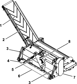
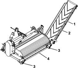
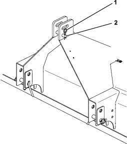
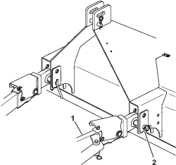
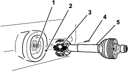
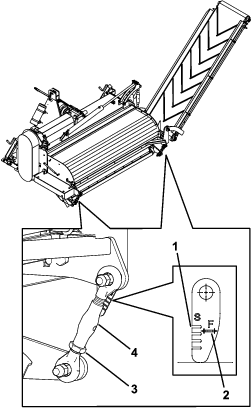
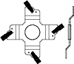
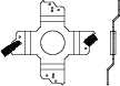
    Grease the machine at the following bearing locations (Figure 28).

    g348515

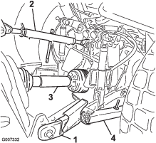
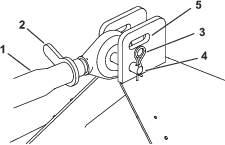
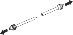
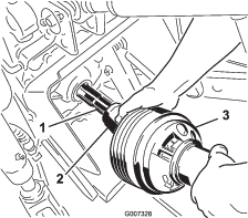
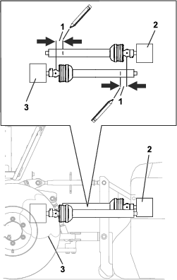
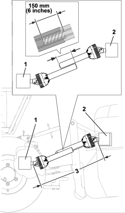
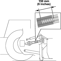
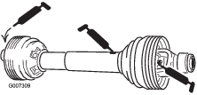
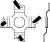
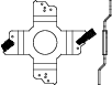
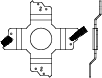
    Grease the PTO driveshaft at the following locations (Figure 29).

    g007309

    Checking the Gearbox Lubrication

    Maintenance Service IntervalMaintenance Procedure
    After the first 20 hours
  • Check the gearbox oil level.
  • Check the gearbox for leaks.
  • Before each use or daily
  • Check the gearbox oil level.
  • Every 50 hours
  • Check the gearbox oil level.
  • Check the gearbox for leaks.
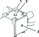
  • Allow the gearbox to cool before checking the lubrication.

    1. Clean debris from the fill plug to avoid contamination (Figure 30).

    2. Remove the fill plug to relieve trapped air.

    3. Remove the socket-head bolt on the rear of the gearbox.

    4. If no fluid spills out, add more fluid until it comes out.

    5. Install the socket-head bolt on the rear of the gearbox (Figure 30).

    6. Install the fill plug.

      g351200

    Changing the Gearbox Lubrication

    Maintenance Service IntervalMaintenance Procedure
    Every 500 hours
  • Change the gearbox oil.
  • The gearbox is filled with SAE140 gear oil or equivalent.

    1. Clean debris from the fill plug and the drain plug to avoid contamination (Figure 30).

    2. Remove the fill plug to relieve trapped air.

    3. Position a short drain pan under the drain plug and remove the drain plug.

      Note: The high viscosity of cool oil extends the drain time (approximately 30 minutes).

    4. After oil is completely drained, install the drain plug.

    5. Remove the socket-head bolt on the back of the gearbox.

    6. Fill the gearbox until fluid comes out the back hole.

    7. Install the socket-head bolt on the rear of the gearbox (Figure 30).

    8. Install the fill plug.

    Inspecting the Belts

    The drive belt(s) on the machine are durable. However, the normal exposure to UV radiation, ozone or incidental exposure to chemicals can deteriorate the rubber compounding over time and lead to premature wear or material loss (i.e. chunking).

    Annual belt inspection is highly recommended for signs of wear, excessive cushion cracks, or large embedded debris with replacement when needed.

    Adjusting the V-Belt Tension

    Maintenance Service IntervalMaintenance Procedure
    After the first 20 hours
  • Check the V-belt tension.
  • Every 50 hours
  • Check the V-belt tension.
  • Make sure that the belts are properly tensioned to ensure that the machine is operating correctly and to prevent unnecessary wear.

    This machine is equipped with adjustable tension pulleys that keep the V-belts tight. Depending on the intensity of using the machine, the driveline could be affected by the wear of the belts.

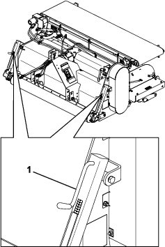
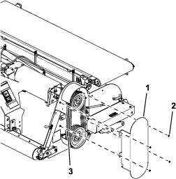
    1. Remove the belt cover.

      g346977
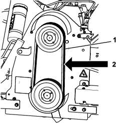
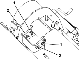
    2. Check the tension of the V-belts by pushing point A with a pressure of 7.5 kg (16-1/2 lb). Proper tension of the belts allows 12.4 mm (1/2 inch) of deflection on each belt (Figure 32).

      Note: If the tension is correct, install the belt cover (Figure 34).

      g348553
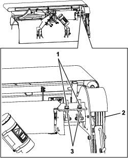
    3. If the tension is not correct, loosen the locknuts under the plate (Figure 34).

    4. Loosen the bolts in the slots (Figure 34).

    5. Adjust the locknuts on top to adjust the tension of the belts.

    6. Check the belt tension and if needed, continue to adjust the top locknuts.

    7. Tighten the lower locknuts under the plate (Figure 34).

    8. Tighten the top locknuts.

    9. Tighten the bolts in the slots.

    10. Install the belt cover.

      g346866
      g346867

    Adjusting the Conveyor Belt Alignment

    If the conveyor belt starts slipping or moving sideways after use or after new installation, adjust the conveyor belt tension.

    1. Check if the rollers and the inside of the conveyor belt are clean. If necessary clean the rollers and remove any dirt inside.

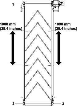
    2. Release the tension of the conveyor belt by loosening the left and right screws.

    3. Mark both sides of the belt with 2 measurement marks a distance of 1000 mm (39-13/32 inch) apart; refer to Figure 35.

      g346659
    4. Adjust the screws on both sides evenly till the distance between the marks has increased to an initial dimension of 1004 mm (39-1/2 inch).

      Note: Make the adjustments evenly on both sides in small steps.

    5. Run the conveyor belt only slowly to detect any belt movement and before any damage occurs.

    6. If the belt keeps slipping, adjust the screws evenly till a maximum of 1010 mm (39-13/16 inch).

    7. If the conveyor belt tends to move to the left, give a little more tension on the lower left adjustment. If the conveyor belt moves to the right, give a little more tension to the lower right adjustment.

      Note: Carry out the adjustments in small steps.

      Belt Tensioning
      Belt movementThe belt moves to the left.The belt moves to the right.
      AdjustmentTighten the lower left screw.Tighten the lower right screw.
    8. After each adjustment, allow the conveyor belt to rotate for at least 10 rotations to position itself to the new alignment before making any further corrections.

    9. If the belt is working properly again, securely lock the screws in place.

    Cleaning the Machine

    Maintenance Service IntervalMaintenance Procedure
    After each use
  • Clean the machine.
  • Important: Do not use brackish or reclaimed water to clean the machine.

    • After daily use, thoroughly wash the machine with a garden hose (without a nozzle) to avoid contamination and seal and bearing damage due to excessive water pressure.

      Note: Use a brush to help remove thick layered, dried, or compacted dirt and debris.

    • Use a mild detergent to clean the covers.

    • Inspect the machine for damage, leaking oil, and component wear.

    • After cleaning the machine, grease all drive lines and roller bearings; refer to Greasing the Attachment.

    Installing the Fraise Blades

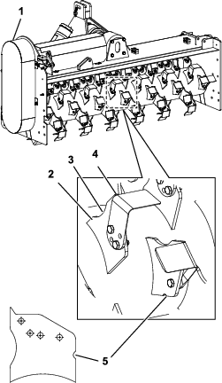
    For the replacement of the fraise blades, it is necessary to point the fraise blades facing to the left or the right to obtain a correct overlap (Figure 36).

    To clarify the correct position, certain rotor plates have a notch cut into them.

    Note: Ensure the knife edge rests against the rotor plate.

    • Install the fraise blades with a notch facing to the left side of the machine.

    • Install the fraise blades without a notch facing to the right side of the machine.

      g348770

    Installing Optional Scarifying Knives

    This machine is equipped with fraise knives but you can also use it with scarifying knives for scarifying the subsoil.

    You can set the distance between the scarifying knives at the following 4 positions:

    • 25 mm (1 inch)

    • 50 mm (2 inches)

    • 75 mm (3 inches)

    • 100 mm (4 inches)

    In order to avoid imbalance, weights are used for the spacing of 50 mm (2 inches), 75 mm (3 inches), and 100 mm (4 inches).

    Use the tables below to select the spacing. The letter W in the tables indicates where the weights are installed and the letter S indicates where the knives are installed.

    Note: If there is no letter in the table cell, this indicates that nothing is installed at that position.

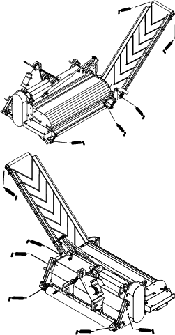
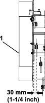
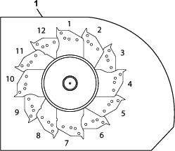
    Use the following graphic to locate the plate sections (Figure 37).

    g348587

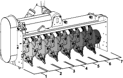
    Row 1 in each table is the closest row abutting the left side plate at 30 mm (1.2 inches). Use this as the start position (Figure 38 and Figure 39).

    g349254
    g348517

    For 25 mm (1 inch) spacing, install knives on all plates.

    Slit Distance—50 mm (2 inches)

     Plate Section
    Row1234567
    1SSSSSSS
    2WWWWWW 
    3WWWWWW 
    4WWWWWWW
    5WWWWWW 
    6WWWWWW 
    7WWWWWWW
    8SSSSSS 
    9SSSSSS 
    10SSSSSSS
    11SSSSSS 
    12SSSSSS 

    Parts needed for 50 mm Distance

    PartQuantity
    Knife38
    Counterweight38

    Slit Distance—75 mm (3 inches)

     Plate Section
    Row1234567
    1SSSSSSS
    2SSSSSS 
    3WWWWWW 
    4       
    5       
    6       
    7SSSSSSS
    8WWWWWW 
    9SSSSSS 
    10       
    11       
    12       

    Parts needed for 75 mm Distance

    PartQuantity
    Knife26
    Counterweight12

    Slit Distance—100 mm (4 inches)

     Plate Section
    Row1234567
    1SSSSSSS
    2       
    3       
    4       
    5WWWWWW 
    6WWWWWW 
    7WWWWWWW
    8       
    9       
    10       
    11SSSSSS 
    12SSSSSS 

    Parts needed for 100 mm Distance

    PartQuantity
    Knife19
    Counterweight19
    25 mm (1 inch) spacing
    g348707
    g348702
    Same as disk 1
    50 mm (2 inch) spacing
    g348703
    Same as disk 1
    75 mm (3 inch) spacing
    g348706
     
    g348704
    g348705
    Disk 1Disk 2Disk 3Same as disk 1
    100 mm (4 inch) spacing
    g348701
    Same as disk 1

    Storage

    Storage Safety

    • Before adjusting, cleaning, storing, or repairing the machine, park the it on a level surface; engage the parking brake of the traction unit; shut off the engine; remove the key; and wait for all movement to stop before leaving the traction unit.

    • Store the machine on the front and rear rollers positioned on a firm, level surface so that it does not sink or roll away.

    • Store the machine away from areas of human activity.

    • Do not allow children to play on or around the stored machine.

    Preparing the Machine for Storage

    Important: Do not use brackish or reclaimed water to clean the machine.

    When the machine is stored for a long period, perform the following procedure:

    1. Clean off any dirt or grease that may have accumulated on the machine or any of the moving parts.

    2. Clean accumulated soil from the knives.

    3. Open the hood and clean out the inside of the machine.

    4. Lubricate all grease fittings.

    5. Support the PTO driveshaft in the stored position with the tether to prevent damage, or remove the PTO and store it under the hood to minimize corrosion.

    6. Touch up any scratches on the painted surfaces.

    7. Replace any missing or damaged decals.

    8. Store the machine inside a dry, secure building. Inside storage reduces maintenance, gives a longer working life, and increases the residual value of the machine. If inside storage is not available, cover the machine with a heavy sheet or tarpaulin and secure it tightly.

    Troubleshooting

    ProblemPossible CauseCorrective Action
    The machine vibrates.
    1. There is an obstacle(s) between the knives
    2. The knives are worn or broken.
    3. The rotor is unbalanced.
    1. Remove the obstacle(s).
    2. Replace with new knives.
    3. Balance the rotor.
    The working depth is not achieved.
    1. The working depth is not correct.
    2. The subsoil is too hard.
    3. The driving speed is too high.
    1. Adjust the working depth properly.
    2. Lower the driving speed or pass over the soil more than once.
    3. Lower the driving speed.
    The soil is too coarse while processing.
    1. The driving speed is too high.
    2. The soil is too wet.
    1. Lower the driving speed.
    2. Wait for better conditions.
    The rotor is jammed.
    1. The soil is too wet.
    2. There is an obstacle(s) between the knives
    3. The driving speed is too high.
    4. There is too much overgrowth.
    1. Wait for better conditions.
    2. Remove the obstacle(s).
    3. Lower the driving speed.
    4. Cut the overgrowth.
    The rotor does not turn.
    1. The V-belts that drive the rotor slip.
    2. The machine is adjusted too deep.
    1. Thighten the V-belts.
    2. Adjust the machine depth.
    The transport belt cannot handle the quantity of material.
    1. The driving speed is too high.
    2. Transport belt turns too slowly.
    1. Lower the driving speed.
    2. Increase the oil flow of the tractor.
    The transport belt moves slowly or does not move.
    1. There is no hydraulic flow.
    2. The transport belt slips.
    1. Check the hydraulic connections.
    2. Tighten the transport belt.