Introduction

The backhoe attachment is intended to be used on a Toro compact tool carrier. It is designed primarily for digging soil for various applications at jobsites. Using this product for purposes other than its intended use could prove dangerous to you and bystanders.

Read this information carefully to learn how to operate and maintain your product properly and to avoid injury and product damage. You are responsible for operating the product properly and safely.

Visit www.the manufacturer.com for product safety and operation training materials, accessory information, help finding a dealer, or to register your product.

Whenever you need service, genuine the manufacturer parts, or additional information, contact an Authorized Service Dealer or the manufacturer Customer Service and have the model and serial numbers of your product ready. Figure 1 identifies the location of the model and serial numbers on the product. Write the numbers in the space provided.

Important: With your mobile device, you can scan the QR code on the serial number decal (if equipped) to access warranty, parts, and other product information.

g352049

This manual identifies potential hazards and has safety messages identified by the safety-alert symbol (Figure 2), which signals a hazard that may cause serious injury or death if you do not follow the recommended precautions.

g000502

This manual uses 2 words to highlight information. Important calls attention to special mechanical information and Note emphasizes general information worthy of special attention.

Warning

CALIFORNIA

Proposition 65 Warning

Use of this product may cause exposure to chemicals known to the State of California to cause cancer, birth defects, or other reproductive harm.

Safety

Danger

There may be buried utility lines in the work area. Digging into them may cause a shock or an explosion.

Have the property or work area marked for buried lines and do not dig in marked areas. Contact your local marking service or utility company to have the property marked (for example, in the US, call 811 or in Australia, call 1100 for the nationwide marking service).

General Safety

Always follow all safety instructions to avoid serious injury or death.

  • Do not transport an attachment with the arms raised. Always transport the attachment close to the ground; refer to Securing the Backhoe for Transport.

  • Have the property or work area marked for buried lines and other objects, and do not dig in marked areas.

  • Read and understand the content of this Operator’s Manual before starting the engine.

  • Use your full attention while operating the machine. Do not engage in any activity that causes distractions; otherwise, injury or property damage may occur.

  • Never allow children or untrained people to operate the machine.

  • Keep your hands and feet away from the moving components and attachments.

  • Do not operate the machine without the guards and other safety protective devices in place and working on the machine.

  • Keep bystanders and pets away from the machine.

  • Stop the machine, shut off the engine, and remove the key before servicing, fueling, or unclogging the machine.

Improperly using or maintaining this machine can result in injury. To reduce the potential for injury, comply with these safety instructions and always pay attention to the safety-alert symbol Graphic
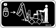
, which means Caution, Warning, or Danger—personal safety instruction. Failure to comply with these instructions may result in personal injury or death.
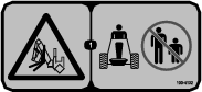
Slope Safety

  • Operate the machine up and down slopes with the heavy end of the machine uphill. Weight distribution changes with attachments. This attachment makes the front of machine the heavy end.

  • Keep the attachment in the lowered position when on slopes. Raising the attachment on a slope affects the stability of the machine.

  • Slopes are a major factor related to loss of control and tip-over accidents, which can result in severe injury or death. Operating the machine on any slope or uneven terrain requires extra caution.

  • Establish your own procedures and rules for operating on slopes. These procedures must include surveying the site to determine which slopes are safe for machine operation. Always use common sense and good judgment when performing this survey.

  • Slow down and use extra care on hillsides. Ground conditions can affect the stability of the machine.

  • Avoid starting or stopping on a slope. If the machine loses traction, proceed slowly, straight down the slope.

  • Avoid turning on slopes. If you must turn, turn slowly and keep the heavy end of the machine uphill.

  • Keep all movements on slopes slow and gradual. Do not make sudden changes in speed or direction.

  • If you feel uneasy operating the machine on a slope, do not do it.

  • Watch for holes, ruts, or bumps, as uneven terrain could overturn the machine. Tall grass can hide obstacles.

  • Use caution when operating on wet surfaces. Reduced traction could cause sliding.

  • Evaluate the area to ensure that the ground is stable enough to support the machine.

  • Use caution when operating the machine near the following:

    • Drop-offs

    • Ditches

    • Embankments

    • Bodies of water

    The machine could suddenly roll over if a track or wheel goes over the edge or the edge caves in. Maintain a safe distance between the machine and any hazard.

  • Do not remove or add attachments on a slope.

  • Do not park the machine on a hillside or slope.

Backhoe Safety

  • Stay in the operator’s position behind the controls while operating the backhoe.

  • Do not dig within 91 cm (3 ft) of the backhoe or stabilizers.

  • Do not overload the machine capacity by attempting to use the backhoe too fast.

  • Check for overhead clearance (i.e., electrical wires, branches, and doorways) before driving under any objects and do not contact them.

Maintenance and Storage Safety

  • Check fasteners at frequent intervals for proper tightness to ensure that the equipment is in safe operating condition.

  • Refer to the Operator’s Manual for important details if you store the attachment for an extended period of time

  • Maintain or replace safety and instruction labels, as necessary.

Safety and Instructional Decals

Graphic

Safety decals and instructions are easily visible to the operator and are located near any area of potential danger. Replace any decal that is damaged or missing.

decal100-4132
decal100-4134
decal133-8061
decal140-7461
decal145-1854
decal145-1851
decal145-1852

Setup

You must obtain and install the Backhoe Kit appropriate for your traction unit. Use the instructions provided in this section to install these kits.

Preparing the Machine

  1. Park the machine on a level surface.

  2. Engage the parking brake.

  3. Lower the loader arms.

  4. Shut off the engine and remove the key.

Greasing the Backhoe

Before using the backhoe for the first time, ensure that all of the fittings are fully greased; refer to Greasing the Backhoe.

Adjusting the Seat

Caution

The seat mounting bracket has several pinch points. You could pinch and/or cut your fingers when adjusting the seat.

Take care to keep your fingers away from the seat mounting bracket when moving the seat up and down and when lowering the seat into position.

  1. Shut off the engine and wait for all moving parts to stop before leaving the operating position.

  2. Tilt the seat forward.

  3. Loosen the knobs on the bottom of the seat (Figure 3) to slide the seat forward or backward as needed.

  4. To adjust the seat height, remove the seat adjustment bolt and nut from the seat stand (Figure 3) and raise or lower the seat as desired.

    g348055
  5. When you attain your desired seat height, install and secure the bolt and nut.

Product Overview

g348000

Become familiar with all the controls (Figure 5) before you start the engine and operate the traction unit.

g352477

Stabilizer Control Levers

Move the stabilizer control levers forward to lower the stabilizers and backward to raise the stabilizers.

Boom Control Lever

Move the boom control lever forward to lower the boom and backward to raise the boom. Move the boom control lever to the right to swing the boom to the right and move it left to swing the boom to the left.

You can also move the boom control lever into an intermediate position (i.e., forward and left, forward and right, backward and left, or backward and right) to swing the boom at the same time as you raise or lower it.

Dipper/Bucket Control Lever

Move the dipper/bucket control lever forward to extend the bucket and backward to retract the bucket. Move the dipper/bucket control lever to the right to dump the bucket and move it left to load the bucket.

You can also move the dipper/bucket control lever into an intermediate position (i.e., forward and left, forward and right, backward and left, or backward and right) to extend or retract the dipper at the same time as you load or dump the bucket.

E-Stop Button

The backhoe has an e-stop button that shuts down the machine when you press it.

You must be sitting in the seat to operate the backhoe; otherwise, the e-stop button does not allow the machine to run.

To manually start the machine after an emergency stop, pull the emergency stop button up.

Note: Specifications and design are subject to change without notice.

Width87.6 cm (34.5 inches)
Length104 cm (41 inches)
Transport height180 cm (71 inches)
Weight382 kg (843 lb)
Digging depth (maximum)208 cm (82 inches)
Bucket rotation180°
Swing arc180°
Stabilizer spread (working)198 cm (78 inches)
Bucket capacity0.7 ft3

Attachments/Accessories

A selection of the manufacturer approved attachments and accessories is available for use with the machine to enhance and expand its capabilities. Contact your Authorized Service Dealer or authorized the manufacturer distributor or go to www.Toro.com for a list of all approved attachments and accessories.

To ensure optimum performance and continued safety certification of the machine, use only genuine Toro replacement parts and accessories. Replacement parts and accessories made by other manufacturers could be dangerous, and such use could void the product warranty.

Operation

Warning

Hydraulic fluid escaping under pressure can penetrate skin and cause injury. Fluid injected into the skin must be surgically removed within a few hours by a doctor familiar with this form of injury; otherwise, gangrene may result.

  • Ensure that all hydraulic-fluid hoses and lines are in good condition and all hydraulic connections and fittings are tight before applying pressure to the hydraulic system.

  • Keep your body and hands away from pinhole leaks or nozzles that eject high-pressure hydraulic fluid.

  • Use cardboard or paper to find hydraulic leaks; never use your hands.

Caution

Hydraulic couplers, hydraulic lines/valves, and hydraulic fluid may be hot. If you contact hot components, you may be burned.

  • Wear gloves when operating the hydraulic couplers.

  • Allow the machine to cool before touching hydraulic components.

  • Do not touch hydraulic fluid spills.

Installing and Removing the Attachment

Refer to the Operator’s Manual for the traction unit for the installation and removal procedure.

Important: Before installing the attachment, position the machine on a level surface, ensure that the mount plates are free of any dirt or debris, and ensure that the pins rotate freely. If the pins do not rotate freely, grease them.

Note: Always use the traction unit to lift and move the attachment.

Warning

If you do not fully seat the quick-attach pins through the attachment mount plate, the attachment could fall off the machine, crushing you or bystanders.

Ensure that the quick-attach pins are fully seated in the attachment mount plate.

Preparing for Operation

  1. Drive to the work location.

  2. If you are using the backhoe with a TX1000, ensure that the hook-and-loop strap (provided in the Fit-Up Kit) is installed on the control panel; refer to the Fit-Up Kit Installation Instructions.

  3. Remove the 2 pins locking the boom in place (Figure 6 and Figure 7) and place them in the storage positions (Figure 8).

    Note: One pin prevents the boom from swinging side to side (Figure 6) and the other prevents the boom from moving up and down (Figure 7).

    g352157
    g352158
    g352175
  4. Push the stabilizer control levers forward to lower both stabilizers until they touch the ground and the front wheels of the traction unit come off of the ground slightly.

  5. Set the throttle to half speed.

Digging a Hole

Using a backhoe with precision and proficiency takes time and practice. In general, dig a hole by extending the dipper and bucket, lowering them into the ground, and then pulling back on the dipper while raising the boom and curling the bucket backward (Figure 9).

g348183

To empty the bucket, swing it to the left or right and extend the dipper and uncurl bucket, dumping the load (Figure 10).

g348211

The distance you extend the dipper and bucket and the size of bite you take will vary greatly with the soil type, moisture content of the soil, and obstructions in the soil, such as tree roots and rocks.

Spend some time practicing with the backhoe to get the feel for how it operates and how to best use it in the conditions in which you work.

Warning

If you dig too close to the backhoe body or stabilizers, the backhoe could undercut the stabilizers or traction unit and the backhoe could fall into the hole, tipping on top of you causing severe injury.

Ensure that you do not dig within 91 cm (3 feet) of the backhoe or stabilizers.

Securing the Backhoe for Transport

Warning

If you do not secure the boom, it could swing or lower during transport or when disconnecting the backhoe from the traction unit. The traction unit could become unstable causing loss of control and you or bystanders could be injured. If the boom swings when disconnecting, it could crush or amputate fingers or hands as you disconnect the attachment locking pins.

Always secure the boom before transport and before disconnecting the backhoe from the traction unit.

  1. Fully raise the boom, retract the dipper, and curl the bucket rearward (Figure 11). Ensure that you center the boom locking pin holes as much as possible.

    g351959
  2. Pull the stabilizer levers rearward until the stabilizers are fully raised and secure them with the locking pins.

  3. Secure the boom by installing the 2 pins removed prior to operation (Figure 12 and Figure 13).

    g352157
    g352158

Operating Tips

  • Do not take large bites of soil. Instead, sweep the bucket through the soil using the swinging motion of the dipper a few inches deep at a time.

  • If the bucket catches in the soil, uncurl the bucket, raise the boom slightly, and continue digging.

  • If your traction unit has a speed selector, set it to the slow (turtle) position while you are learning how to operate the backhoe (this will slow the backhoe down). Set it to the fast position (rabbit) once you feel you have mastered the use of the backhoe.

  • If your traction unit has a flow divider, set it to the 11 o’clock position.

Maintenance

Recommended Maintenance Schedule(s)

Maintenance Service IntervalMaintenance Procedure
After the first hour
  • Check all bolts and nuts for proper tightness and tighten them if needed.
  • Before each use or daily
  • Grease all fittings.
  • Every 25 hours
  • Inspect for leaks.
  • Before storage
  • Grease all fittings.
  • Wash the backhoe.
  • Paint all scratched or bare metal surfaces.
  • Greasing the Backhoe

    Maintenance Service IntervalMaintenance Procedure
    Before each use or daily
  • Grease all fittings.
  • Every 25 hours
  • Inspect for leaks.
  • Before storage
  • Grease all fittings.
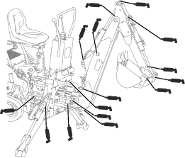
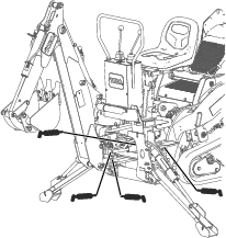
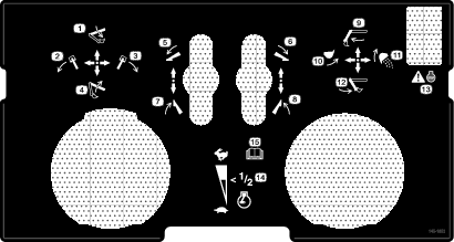
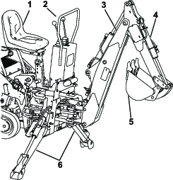
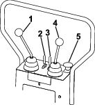
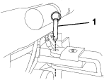
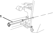
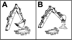
  • Grease the 19 fittings, as shown in Figure 14 and Figure 15, every 8 operating hours. Grease all fittings immediately after every washing.

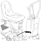
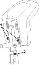
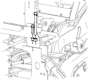
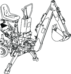
    Also, grease the fitting in the swing cylinder pivot pin, located under the seat column (Figure 16).

    Grease Type: General-purpose grease

    1. Park the machine on a level surface, disengage the auxiliary hydraulics lever, lower the attachment, and engage the parking brake (if equipped).

    2. Shut off the engine and remove the key.

    3. Clean the grease fittings with a rag.

    4. Connect a grease gun to each fitting.

    5. Pump grease into the fittings until grease begins to ooze out of the bearings.

    6. Wipe up any excess grease.

    g351963
    g352087
    g352076

    Storage

    1. Before long term storage wash the attachment with mild detergent and water to remove dirt and grime.

    2. Apply grease to all grease fittings.

    3. Check and tighten all bolts, nuts, and screws. Repair or replace any parts that are damaged or worn.

    4. Paint all scratched or bare metal surfaces.

      Note: Paint is available from your Authorized Service Dealer.

    5. Store the attachment in a clean, dry garage or storage area. Cover it to protect it and keep it clean.

    Troubleshooting

    ProblemPossible CauseCorrective Action
    The backhoe does not operate.
    1. The hydraulic coupler not completely connected.
    2. The auxiliary-hydraulics valve on the traction unit is not fully engaged.
    3. The transport pins were not removed.
    4. The hydraulic-fluid level is low.
    5. A hydraulic coupler is damaged.
    6. A hydraulic hose is obstructed.
    7. A hydraulic hose is pinched.
    8. The auxiliary-hydraulic valve on the traction unit is not opening.
    9. A hydraulic coupler not completely connected
    10. A piston rod is bent.
    11. The seat switch is not functioning properly.
    12. The operator is not sitting in the seat.
    13. The e-stop button is activated.
    1. Check and tighten all couplers.
    2. Engage the valve.
    3. Remove the pins.
    4. Fill the traction unit hydraulic tank.
    5. Check the couplers and replace any that are defective.
    6. Find and remove the obstruction.
    7. Replace the hose.
    8. Repair the valve.
    9. Check and tighten all couplers.
    10. Contact your Authorized Service Dealer.
    11. Check the seat switch connections.
    12. Sit in the seat to operate the backhoe.
    13. Reset the emergency stop button.
    The backhoe is operating slowly.
    1. The hydraulic fluid is cold
    2. The engine speed is too slow.
    3. A hydraulic hose is pinched.
    4. A cylinder is bent.
    5. The hydraulic pump is damaged.
    1. Allow the engine to warm the hydraulic fluid before operating.
    2. Increase the throttle speed of the traction unit.
    3. Replace the hose.
    4. Contact your Authorized Service Dealer.
    5. Contact your Authorized Service Dealer.
    The backhoe fails to hold up a load (all loads will normally settle down over a long period of time).
    1. A hydraulic hose is damaged.
    2. A cylinder is damaged.
    3. A control valve is damaged.
    1. Replace the hose.
    2. Contact your Authorized Service Dealer.
    3. Contact your Authorized Service Dealer.
    The hydraulic fluid is leaking.
    1. A hydraulic hose is damaged.
    2. The hydraulic system is damaged.
    1. Replace the hose.
    2. Contact your Authorized Service Dealer.
    The swing cylinder is malfunctioning.
    1. There are damaged cylinders or swing restrictors.
    1. Contact your Authorized Service Dealer.
    The control valve sticking or working hard.
    1. The hydraulic fluid is dirty.
    2. A valve is damaged or dirty.
    3. A cylinder is damaged.
    1. Change the hydraulic fluid.
    2. Contact your Authorized Service Dealer.
    3. Contact your Authorized Service Dealer.
    The backhoe is spongy or jerky during operation.
    1. The hydraulic-fluid level is low.
    2. There is air in the hydraulic system.
    3. The hydraulic fluid is cold.
    4. A hydraulic hose is pinched.
    1. Fill the hydraulic tank on the traction unit.
    2. Extend the cylinders as far as possible and hold them in an extended position for several seconds.
    3. Allow the engine to warm the hydraulic fluid before operating.
    4. Replace the hose.