Installation
Preparing the Machine
-
Park the machine on a level surface.
-
Engage the parking brake.
-
Disengage the PTO and lower the attachment(s).
-
Shut off the engine and remove the key.
Installing the Lights with a Sun Shade
Parts needed for this procedure:
| Light bracket | 2 |
| Large speed-nut | 8 |
| Small speed-nut | 8 |
| Screw (#10 x 1-1/4 inches) | 8 |
| Front light | 2 |
| Rear light | 2 |
| Carriage bolt (5/16 x 1 inch) | 4 |
| Flange nuts (5/16 inch) | 4 |
| Carriage bolt (3/8 x 5 inches) | 4 |
| Carriage bolt (3/8 x 4 inches) | 4 |
| Carriage bolt (3/8 x 3 inches) | 4 |
| Flange locknuts (3/8 inch) | 4 |
| Mounting bracket | 2 |
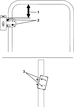
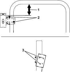
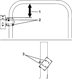
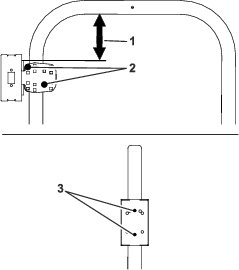
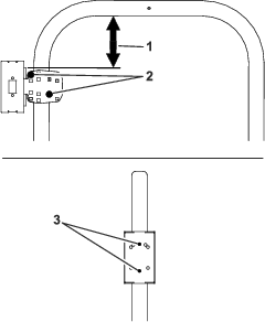
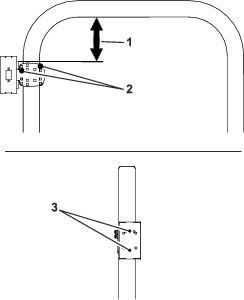
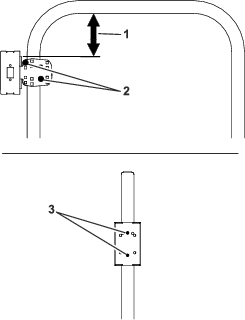
Note: The location of the sun shade support determines the location of the light on the roll bar.
-
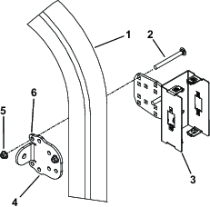
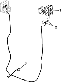
Install the large speed nuts to the top and bottom of the light bracket (Figure 1).
-
Install the small speed nuts to the sides of the light bracket (Figure 1).
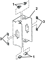
-
Determine which holes to use for installing the mounting bracket to the light bracket. Refer to the table below and Figure 3.
-
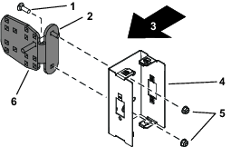
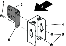
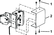
Install the mounting bracket to the light bracket as shown in Figure 2.
Note: Ensure the mounting-bracket tab is pointing backwards (Figure 2).
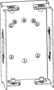
Note: There are 2 positions for B and 2 in Figure 3. The correct holes are determined if you are installing the lights on the left or right side of the ROPS. Ensure the lights point straight back.
Hole Positions to Use (Figure 3) Machine B and 1 Groundsmaster 4000 and 4100 Series, ReelMaster 5000 Series, and ReelMaster 3000 Series C and 2 Groundsmaster 4500, 4700 Series, and GroundsMaster 7000 A and 1 All other machines -
Locate the bracket for the sunshade support and note the orientation of the bracket tab.
-
Make note of which holes the existing U-bolts use when removing it.
-
Remove the U-bolt from the bracket attached to the sun-shade support. Discard the U-bolt.
-
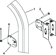
Before installing the light assembly to the roll bar, you need to determine the length of bolts to use. Use the 3/8 inch carriage bolts that are 3, 4, or 5 inches long.
-
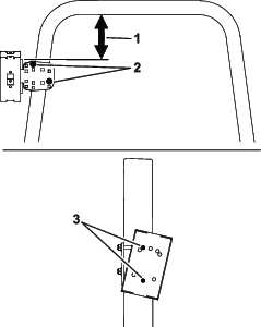
Using the holes used by the U-bolt, assemble the light assembly to the roll bar with existing sun-shade bracket, 4 carriage bolts (3/8 x 3, 4 or 5 inches), and 4 flange locknuts (3/8 inch); refer to Figure 5.
Note: The length of the carriage bolts is determined by the size of the rollbar on your machine. Use the appropriate length to fit around your rollbar.
-
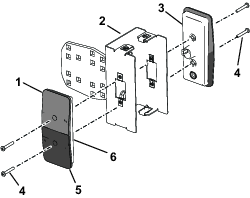
Align the front and rear lights to the light bracket with the yellow lens positioned as shown in Figure 6.
-
Install the front light to the front of the light bracket with 2 screws (#10 x 1-1/4 inches); refer to Figure 6.
-
Install the rear light to the light bracket with 2 screws (#10 x 1-1/4 inches); refer to Figure 6.
Installing the Lights without a Sunshade
Parts needed for this procedure:
| Light bracket | 2 |
| Large speed-nut | 8 |
| Small speed-nut | 8 |
| Screw (#10 x 1-1/4 inches) | 8 |
| Front light | 2 |
| Rear light | 2 |
| Carriage bolt (5/16 x 1 inch) | 4 |
| Flange nuts (5/16 inch) | 4 |
| Carriage bolt (3/8 x 5 inches) | 4 |
| Carriage bolt (3/8 x 4 inches) | 4 |
| Carriage bolt (3/8 x 3inches) | 4 |
| Mounting bracket | 2 |
| Rollbar bracket | 2 |
-
Install the large speed nuts to the top and bottom of the light bracket (Figure 7).
-
Install the small speed nuts to the sides of the light bracket (Figure 7).
-
Determine which holes to use for installing the mounting bracket to the light bracket and the position on the rollbar. Refer to the table below and Figure 8 through Figure 18.
-
Install the mounting bracket to the light bracket as shown in Figure 8.
Note: Ensure the mounting-bracket tab points in the correct position (Figure 8).
Note: There are 2 positions for B and 2 in Figure 9. The correct holes are determined if you are installing the lights on the left or right side of the ROPS. Ensure the lights point straight back.
Hole Positions to Use (Figure 9) Machine B and 1 Groundsmaster 4000 and 4100 Series, ReelMaster 5000 Series, and ReelMaster 3000 Series C and 2 Groundsmaster 4500, 4700 Series, and GroundsMaster 7000 A and 1 All other machines Note: Each machine series has a specific location on the rollbar. Refer to Figure 10 through Figure 18.

-
Before installing the light assembly to the roll bar, you need to determine the length of bolts to use. Use the 3/8 inch carriage bolts that are 3, 4, or 5 inches long.
-
Assemble the light assembly to the roll bar with rollbar bracket, 4 carriage bolts (3/8 x 3, 4 or 5 inches), and 4 flange locknuts (3/8 inch); refer to Figure 10 through Figure 18 and Figure 19.
Note: The length of the carriage bolts is determined by the size of the rollbar on your machine. Use the appropriate length to fit around your rollbar.
-
Align the front and rear lights to the light bracket with the yellow lens positioned as shown in Figure 20.
-
Install the front light to the front of the light bracket with 2 screws (#10 x 1-1/4 inches); refer to Figure 20.
-
Install the rear light to the light bracket with 2 screws (#10 x 1-1/4 inches); refer to Figure 20.
Routing the Wire Harness
-
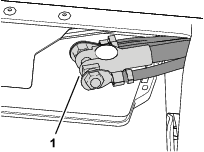
Locate the 12 pin connector on your machine’s main harness under the seat platform.
-
Plug the wire harness 12-pin connector into the main harness (Figure 21).
-
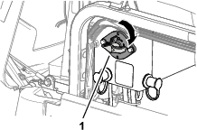
Route the harness up each side of the roll bar.
Note: Ensure the harness is not pinched and when certain rollbars are folded.
-
Plug the harness into the front and rear lights (Figure 21).
-
Install the cover onto the light brackets with 8 bolts (1/4 x 3/4 inch); refer to .
Connecting the Battery
Connecting the Battery
-
Assemble the terminal of the negative battery cable to the negative post of the battery, and tighten the nut of the terminal by hand (Figure 23).
-
Test the lights of the kit.
-
Close the battery compartment door securely.
Connecting the Battery
-
Rotate the battery disconnect switch to the ON position (Figure 24).
-
Test the lights of the kit.
-
Close the hood and latch it.