| Maintenance Service Interval | Maintenance Procedure |
|---|---|
| Before each use or daily |
|
Introduction
When properly installed, this attachment converts a vehicle into a dedicated turf spray application machine, and it is intended to be used by professional, hired operators in commercial applications. It is designed primarily for spraying on well-maintained lawns in parks, golf courses, sports fields, and on commercial grounds.
Read this information carefully to learn how to operate and maintain your product properly and to avoid injury and product damage. You are responsible for operating the product properly and safely.
Visit www.Toro.com for more information, including safety tips, training materials, accessory information, help finding a dealer, or to register your product.
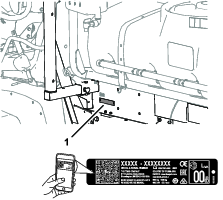
Whenever you need service, genuine Toro parts, or additional information, contact an Authorized Service Dealer or Toro Customer Service and have the model and serial numbers of your product ready. Figure 1 identifies the location of the model and serial numbers on the product. Write the numbers in the space provided.
Important: Important: With your mobile device, you can scan the QR code on the serial number decal (if equipped) to access warranty, parts, and other product information.
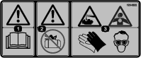
This manual identifies potential hazards and has safety messages identified by the safety-alert symbol (Figure 2), which signals a hazard that may cause serious injury or death if you do not follow the recommended precautions.

This manual uses 2 words to highlight information. Important calls attention to special mechanical information and Note emphasizes general information worthy of special attention.
This product complies with all relevant European directives; for details, please see the separate product specific Declaration of Conformity (DOC) sheet.
It is a violation of California Public Resource Code Section 4442 or 4443 to use or operate the engine on any forest-covered, brush-covered, or grass-covered land unless the engine is equipped with a spark arrester, as defined in Section 4442, maintained in effective working order or the engine is constructed, equipped, and maintained for the prevention of fire.
Warning
CALIFORNIA
Proposition 65 Warning
Use of this product may cause exposure to chemicals known to the State of California to cause cancer, birth defects, or other reproductive harm.
Safety
Improper use or maintenance by the operator or owner can result in injury. To reduce the potential for injury, comply with these safety instructions and always pay attention to the safety-alert symbol (Figure 2), which means Caution, Warning, or Danger—personal safety instruction. Failure to comply with the instruction may result in personal injury or death.
This machine has been designed in accordance with the requirements of SAE J2258.
General Safety
This product is capable of causing personal injury. Always follow all safety instructions to avoid serious personal injury.
-
Read and understand the contents of this Operator’s Manual before starting the engine.
-
Use your full attention while operating the machine. Do not engage in any activity that causes distractions; otherwise, injury or property damage may occur.
-
Use appropriate personal protective equipment (PPE) to guard against contact with chemicals. Chemical substances used in the sprayer system may be hazardous and toxic.
-
Do not put your hands or feet near moving components of the machine.
-
Do not operate the machine without all guards and other safety protective devices in place and working on the machine.
-
Keep clear of any discharge area of the sprayer nozzles and spray drift. Keep bystanders and children out of the operating area.
-
Never allow children to operate the machine.
-
Park the machine on a level surface, engage the parking brake, shut off the engine, remove the key (if equipped), and wait for all movement to stop before you leave the operator’s position. Allow the machine to cool before adjusting, servicing, cleaning, or storing it.
Improperly using or maintaining this machine can result in injury.
To reduce the potential for injury, comply with these safety instructions
and always pay attention to the safety-alert symbol  , which means Caution, Warning,
or Danger—personal safety instruction. Failure to comply with
these instructions may result in personal injury or death.
, which means Caution, Warning,
or Danger—personal safety instruction. Failure to comply with
these instructions may result in personal injury or death.
Not all the attachments that adapt to this machine are covered in this manual. Refer to the operator’s manual provided with each attachment for additional safety instructions.
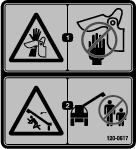
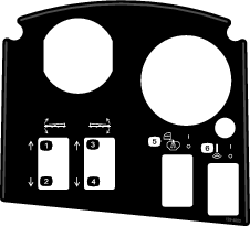
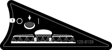
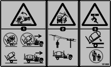
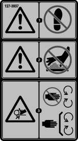
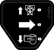
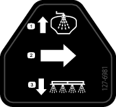
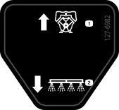
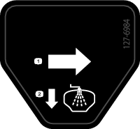
Safety and Instructional Decals
 |
Safety decals and instructions are easily visible to the operator and are located near any area of potential danger. Replace any decal that is damaged or missing. |


Setup
Note: Determine the left and right sides of the machine from the normal operating position.
Note: If you have questions or need additional information regarding the spray control system, refer to the Operator’s Manual supplied with the system.
Important: This sprayer is sold without spray nozzles.To use the sprayer, you must obtain and install the nozzles. Contact your authorized Toro distributor for information on the available section kit and accessories. After you install your nozzles and before using the sprayer for the first time, adjust the section bypass valves so that the pressure and application rate remains the same for all sections when you turn 1 or more sections off. Refer to Calibrating the Sprayer Flow.
Important: The Multi-Pro WM turf sprayer requires a 4-post ROPS or cab installed with the Workman vehicle.
Removing the Existing Bed
Caution
The full bed weighs approximately 95 kg (210 lb). You can injure yourself if you remove the bed without aid.
-
Do not try to install or remove the bed by yourself.
-
Get the help of 2 or 3 other people or use an overhead crane.
-
Park the machine on a level surface, engage the parking brake, and start the engine.
-
Move the hydraulic lift lever forward and lower the bed until the clevis pins for the cylinder rod end lift cylinders are loose in the mounting slots of the bed mounting plates.
-
Release the hydraulic lift lever, set the hydraulic lift lock lever, shut off the engine, and remove the key; refer to the Operator’s Manual of your machine.
-
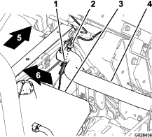
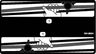
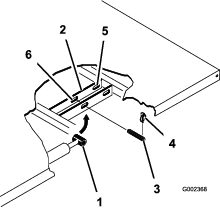
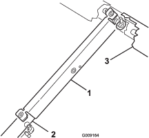
Remove the lynch pins from the outer ends of the cylinder rod clevis pins (Figure 3).
-
Remove the clevis pins securing the cylinder rod ends to the bed mounting plates by pushing the pins toward the centerline of the machine (Figure 3).
-
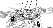
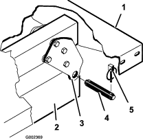
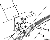
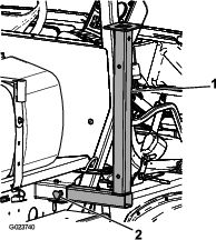
Remove the lynch pins and clevis pins securing the pivot brackets of the bed to the frame channels of the machine (Figure 4).
-
Lift the bed off the vehicle.
-
Stow the lift cylinders in storage clips.
Preparing to Install the Tank Skid
Parts needed for this procedure:
| Rear PTO Kit, Heavy-Duty Workman Vehicle (HD-Series Models with a Manual Transmission) | 1 |
| High-Flow Hydraulics Kit, Workman HDX-Auto Utility Vehicle (Non-TC—HDX-Auto Model) | 1 |
| Multi Pro WM Turf Sprayer Finishing Kit, Manual Workman Utility Vehicle (HD-Series Models with a Manual Transmission) | 1 |
| Multi Pro WM Turf Sprayer Finishing Kit, Automatic Workman Utility Vehicle (HDX-Auto Model) | 1 |
Installing the Rear PTO Kit for Heavy Duty Workman Vehicles (HD-Series Models with a Manual Transmission)
For HD- and HDX-Series Workman models with a manual transmission, fully install the Rear PTO Kit for Heavy-Duty Workman Vehicles; refer to the Installation Instructions for the Rear PTO Kit for Heavy Duty Workman Vehicles.
High-Flow Hydraulics Kit, Workman HDX-Auto Utility Vehicle (Non-TC—HDX-Auto Model)
Fully install the High-Flow Hydraulics Kit for Workman HDX-Auto Utility Vehicles; refer to the Installation Instructions for the High-Flow Hydraulics Kit, Workman HDX-Auto Utility Vehicle.
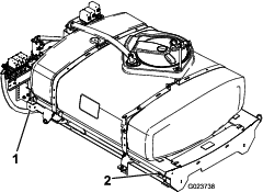
Lifting the Sprayer Skid
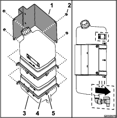
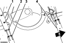
Using lifting equipment with a 408 kg (900 lb) lift capacity, lift the tank skid from the shipping crate at the 2 front and 2 rear lift points (Figure 5).
Note: Ensure that the tank skid is raised high enough to install the jack stands.
Multi Pro Workman Turf Sprayer Finishing Kit (HD-Series Models with a Manual Transmission)
For HD- and HDX-Series Workman models with a manual transmission, complete the steps in the Multi Pro WM Turf Sprayer Finishing Kit for Manual Workman Utility Vehicles; refer to the Installation Instructions for the Multi Pro WM Turf Sprayer Finishing Kit, Manual Workman Utility Vehicle.
Multi Pro Workman Turf Sprayer Finishing Kit (HDX-Auto Model)
HDX-Automatic Series Workman models, complete the steps in the Multi Pro WM Turf Sprayer Finishing Kit for Automatic Workman Utility Vehicles; refer to the Installation Instructions for the Multi Pro WM Turf Sprayer Finishing Kit, Automatic Workman Utility Vehicle.
Installing the Hold-Down Brackets for the Tank Skid
Parts needed for this procedure:
| Hold-down brackets | 2 |
-
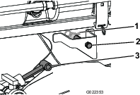
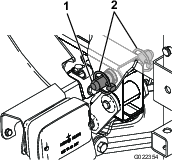
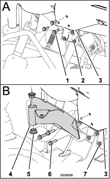
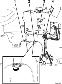
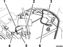
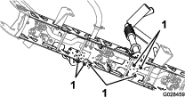
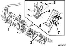
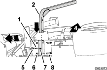
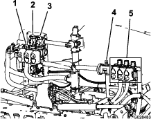
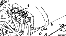
Remove the 2 rear flange-head bolts and 2 flange locknuts that secure the support bracket for the engine tube to the frame of the machine (Figure 6).
Note: Retain the fasteners for later use.
-
Rotate the lift cylinder to provide clearance to install the hold-down bracket for the tank skid (Figure 6).
-
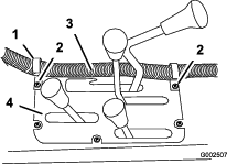
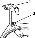
Assemble the hold-down brackets to support bracket and frame the using the 2 flange-head bolts and flange locknuts removed in step 1 (Figure 7).
-
Torque the bolts and nuts to 91 to 113 N∙m (67 to 83 ft-lb).
-
Repeat steps 1 to 4 at the opposite side of the machine.
Installing the Tank Skid
Parts needed for this procedure:
| Tank and skid assembly | 1 |
| Clevis pins | 2 |
| Tapered clevis pin | 2 |
| Hairpins | 2 |
| Lynch pins | 4 |
| Bolt (1/2 x 1-1/2 inches) | 2 |
| Nuts (1/2 inch) | 2 |
Danger
The sprayer tank assembly represents a stored energy hazard. If not properly retained when installing or removing the assembly, it can move or fall and injure you or other bystanders.
Use straps and an overhead lift to support the sprayer tank assembly during installation, removal, or any maintenance whenever you remove retaining fasteners.
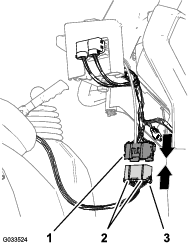
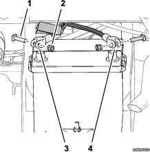
-
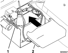
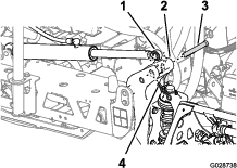
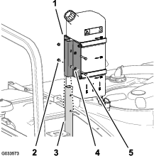
Using a lift, raise the tank skid assembly (Figure 8) and position it over the vehicle frame with the pump and valve assemblies facing rearward.
Note: Have another person help you perform the following steps.
-
Slowly lower the tank skid onto the frame of the machine.
-
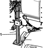
Extend the lift cylinders to the brackets on the tank skid, and align the cylinder fittings with the holes in the tank skid brackets (Figure 9).
-
Secure the tank skid to the lift cylinders with the clevis pins and hairpins at both sides of the machine.
-
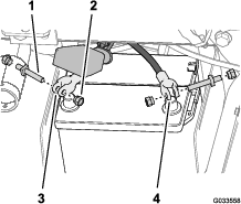
Line up the holes in the pivot lugs at the rear of the tank skid assembly with the holes in the bed pivot tube at the end of the vehicle frame (Figure 10).
-
Install a tapered clevis pin and 2 lynch pins to the pivot lug to secure the tank assembly to the frame (Figure 10).
-
Extend the lift cylinders to raise the tank and support its weight.
Note: Disconnect the tank assembly from the lifting equipment.
-
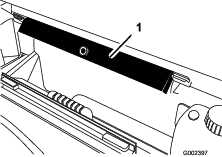
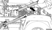
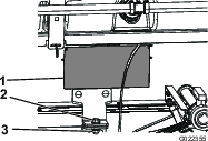
Remove the bed support from the storage brackets on back of the ROPS panel (Figure 11).
-
Push the bed support onto the cylinder rod, making sure that the support end tabs rest on the end of cylinder barrel and on the cylinder rod end (Figure 12).
Assembling the Drain Valve
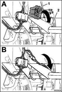
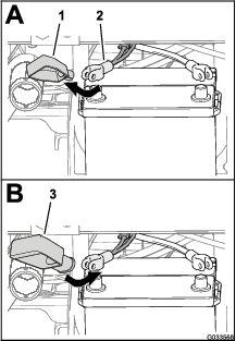
-
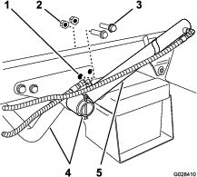
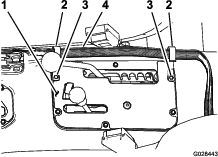
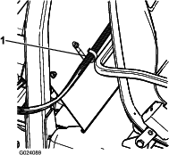
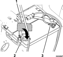
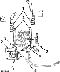
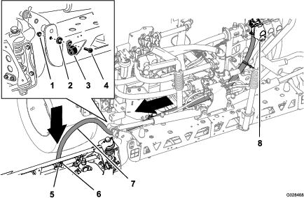
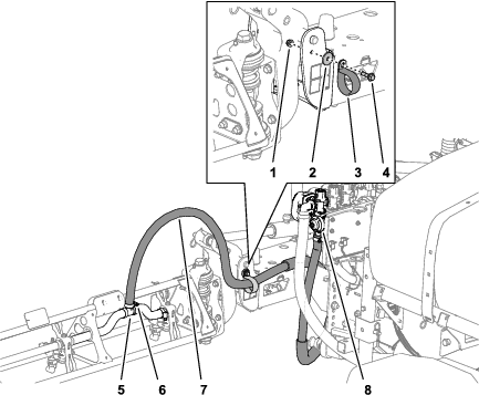
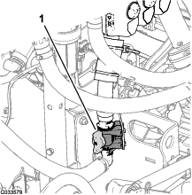
Remove the cable tie that secures the drain valve and hose for the sprayer tank to the skid channel (Figure 13).
-
Move the drain valve and hose outboard of the skid channel (Figure 14A).
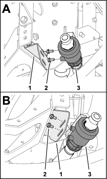
-
Remove the 2 flange-head bolt (5/16 x 5/8 inch) from the case of the drain valve (Figure 14).
-
Assemble the drain valve to the drain-valve bracket (Figure 14B) with the 2 flange-head bolts (5/16 x 5/8 inch) that you removed in step 3.
-
Tighten 2 flanged-head bolts by hand (Figure 14B).
Disconnecting the Battery
Warning
Incorrect battery cable routing could damage the sprayer and cables causing sparks. Sparks can cause the battery gasses to explode, resulting in personal injury.
-
Always disconnect the negative (black) battery cable before disconnecting the positive (red) cable.
-
Always connect the positive (red) battery cable before connecting the negative (black) cable.
Warning
Battery terminals or metal tools could short against metal sprayer components causing sparks. Sparks can cause the battery gasses to explode, resulting in personal injury.
-
When removing or installing the battery, do not allow the battery terminals to touch any metal parts of the sprayer.
-
Do not allow metal tools to short between the battery terminals and metal parts of the sprayer.
-
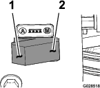
Squeeze the sides of the battery cover to release the tabs from the slots in the battery base, and remove the battery cover from the battery base (Figure 15).
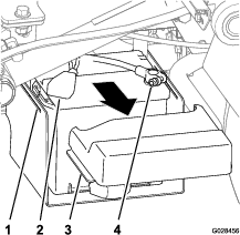
-
Slide the cover back and remove the negative battery terminal from the battery (Figure 15).
-
Remove the positive battery terminal from the battery (Figure 15).
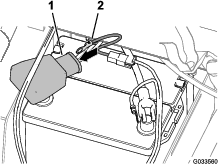
Connecting the Speed Sensor Harness
Connecting the Speed Sensor Harness (HD-Series Models with a Manual Transmission)
-
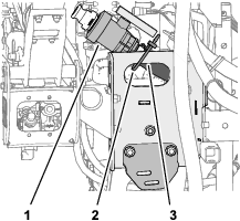
At the wire harness for the sprayer, locate the 3-socket connector for the speed sensor circuit and the 3-pin connector for the vehicle circuit.
-
At the transaxle of the machine, connect the 3-pin connector of the wire harness of the machine for speed sensor into the 3-socket connector of the sprayer harness for the speed sensor (Figure 16).
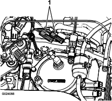
-
Connect the 3-pin connector for the vehicle circuit of the wire harness of the sprayer into the 3-pin socket for the vehicle circuit of the wire harness for the machine.
Connecting the Speed Sensor Harness (HDX-Auto Model)
Coupling the Sprayer Pump
-
For HD-series models with a manual transmission, couple the PTO shaft to the transaxle PTO; refer to the Installation Instructions for the Multi Pro WM Turf Sprayer Finishing Kit, Manual Workman Utility Vehicle.
-
For HDX-Auto model—connect the hydraulic motor hoses to the quick-disconnect fittings at the high-flow hydraulic panel; refer to the Installation Instructions for the Multi Pro WM Turf Sprayer Finishing Kit, Automatic Workman Utility Vehicle.
Installing the Control Console to the Machine
Parts needed for this procedure:
| Console mounting bracket | 1 |
| Flange locknut (5/16 inch) | 3 |
| Flange-head bolt (5/16 inch) | 3 |
| Plastic bushing | 2 |
| Control console | 1 |
| Spring-clip pin | 1 |
| Hand knob | 1 |
Installing the Console Mounting Bracket
Note: On some Workman vehicles, the control mount plate is attached to the dashboard at the same location where the bracket for the optional hand throttle kit is mounted. If the hand throttle kit is installed, you need to remove the bracket of the hand throttle assembly from the dashboard, align the control mount plate to the dash, and install the hand throttle bracket on top of the control mount plate. Refer to the Hand Throttle Kit Installation Instructions for directions on removing and installing the hand throttle assembly.
-
Remove the 3 bolts and 3 nuts that secure the lower-center portion of the dash panel to the dash support bracket (Figure 18).
Note: Some older Workman machines may use 4 bolts and flange nuts.
Note: Discard the bolts and nuts.
-
Align the holes in the mounting bracket for the control console with the holes in the dash and support bracket (Figure 18).
-
Assemble the mounting bracket dash panel and support bracket with the 3 flange-head bolts (5/16 x 1 inch) and 3 flange locknuts (5/16 inch).
-
Torque the nuts and bolts to (Figure 18).
-
Insert the 2 plastic bushings into the mounting bracket (Figure 18).
Installing the Control Console to the Machine
-
Remove the hairpin securing the pivot pin of the control console to the storage bracket on the sprayer tank.
-
Install the control console onto the control mounting bracket and secure the control console with the spring-clip pin (Figure 19).
Note: Ensure that the spring clip is rotated over the pivot pin to positively secure the spring-clip pin.
-
Install the hand knob and tighten it to prevent the console from rotating during operation (Figure 19).
Installing the Electrical Harnesses for the Sprayer
Parts needed for this procedure:
| J-clips | 3 |
| Bolt (1/4 x 3/4 inch) | 1 |
| Flange nut (1/4 inch) | 1 |
Routing the Rear Electrical Harness for the Sprayer to the Control Console
-
Install 2 J-clips in the center console at the points located in Figure 20 or Figure 21 using the existing screws.
-
Install a J-clip behind the passenger seat (Figure 22) using a bolt (1/4 x 1/2 inch) and a flanged nut (1/4 inch).
-
Secure the control console harness to the console and ROPS cover using the J-clips (Figure 22).
Connecting the Rear Electrical Harness to the Front Electrical Harness at the Control Console
-
Align the 2 keys of the 38-pin connector of the rear wire harness for the sprayer with the 2 keyways of the 38-socket connector of the front wire harness connected to the control console (Figure 23).
-
Plug the rear wire-harness connector into the front wire harness connector until the latches of the connectors snap together securely (Figure 23).
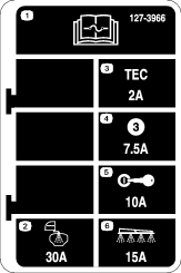
Installing the Sprayer Fuse Block
Parts needed for this procedure:
| Fuse decal (127–3966) | 1 |
-
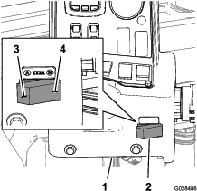
At the control console for the sprayer, route the branch of the front wire harness with the fuse blocks between the bottom of the dash panel and the cross tube of the machine chassis and down toward the forward side of the fuse block of the machine (Figure 24).
-
Locate the uninsulated receptacle terminal at the end of the open, yellow power wire of the fuse block for the machine and the insulated blade terminal at the end of the yellow, optional power wire of the fuse block of the sprayer wiring (Figure 25).
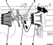
-
Connect the uninsulated receptacle terminal of the fuse block for the machine to the insulated blade terminal of the fuse block of the sprayer (Figure 25).
-
Align the T-fittings on the of the fuse block of the sprayer to the T-slots of the fuse block for the machine and slide the sprayer fuse block into the slots until the fuse block is fully seated (Figure 26).
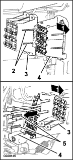
-
Attach the fuse decal on a surface near the fuse block for the sprayer.
Connecting the Sprayer Harness to the Battery
Parts needed for this procedure:
| Battery terminal bolt | 2 |
| Clamp nut | 2 |
| Cover—wide (battery terminal—red) | 1 |
Preparing the Positive Battery Terminal
Warning
Incorrect battery cable routing could damage the sprayer and cables, causing sparks. Sparks can cause the battery gasses to explode, resulting in personal injury.
Always connect the positive (red) battery cable before connecting the negative (black) cable.
-
Remove the nuts and T-bolts at the clamps of the positive and negative battery cables (Figure 27).
Note: You no longer need the nuts and T-bolts.
-
Remove the cover (narrow) from the positive battery cable (Figure 28).
Note: You no longer need the narrow battery cover.
-
Install the wide battery cover over the positive battery cable as shown in Figure 28.
Note: Slide the cover far enough over the cables to allow access to the post clamp.
-
Align the ring terminal of the fusible link (sprayer wire harness) though the wide battery cover as shown in Figure 29.
-
Loosely assemble a terminal bolt and a clamp nut to the positive and negative battery-cable clamps (Figure 30).
-
Secure the ring terminal of the fusible link (sprayer wire harness) to the post of the terminal bolt that you assembled to the positive battery cable with a clamp nut (Figure 31).
-
Secure the ring terminal of the negative wire (black—sprayer wire harness) to the post of the terminal bolt that you assembled to the negative battery cable with a clamp nut (Figure 31).
-
Assemble the positive battery cable onto the positive battery post and tighten the clamp nut by hand (Figure 32).
-
Assemble the negative battery cable onto the negative battery post and tighten the clamp nut by hand.
-
Squeeze the sides of the battery cover, align the tabs of the cover with the slots in the battery base, and release the battery cover (Figure 33).
Lowering the Tank Skid
Parts needed for this procedure:
| Bolt (1/2 x 1-1/2 inch) | 2 |
| Locknut (1/2 inch) | 2 |
-
Start the machine and raise the tank skid slightly with the lift cylinders.
-
Remove the bed support from the lift cylinder and stow the support in the storage brackets at the back of the ROPS panel (Figure 34 and Figure 35).
-
Use lift cylinders to slowly lower the tank to the frame.
Note: Have another person observe the tank skid as it lowers. Look for hoses and wiring that might become pinched or bent.
-
Check the alignment of the tank skid to the frame of the machine.
-
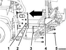
Remove the access panels at both sides of the skid frame (Figure 36).
-
Check the hoses or wiring that you can see through the opening in the skid frame for signs of pinching or bending.
Important: If any hoses or wiring on the tank skid assembly are pinched or bent, raise the assembly up, adjust its positioning, and tie the items back.
-
Align the front mounting brackets with the hold-down brackets installed in Installing the Hold-Down Brackets for the Tank Skid.
-
Secure the hold down bracket of the tank skid assembly to the bed bracket on the frame at each side of the machine with a bolt (1/2 x 1-1/2 inches) and a locknut (1/2 inch) as shown in Figure 36.
-
Torque the bolt and locknut to 91 to 113 N∙m (67 to 83 ft-lb).
-
Repeat steps 7 through 9 at the other side of the tank skid and machine.
Installing the Center Boom Section
Parts needed for this procedure:
| Center-boom assembly | 1 |
| Bolt (3/8 x 1 inch) | 10 |
| Flange locknut (3/8 inch) | 10 |
| Boom-transport cradle | 2 |
| Bolt (1/2 x 1-1/4 inches) | 4 |
| Flange nut (1/2 inch) | 4 |
Assembling the Boom-Transport Cradles
-
Attach lifting equipment to the center boom section and remove it from the shipping container.
-
Align the boom transport cradles to the center boom section (Figure 37).
-
Assemble the cradles to the boom section (Figure 37 and Figure 38) with 6 bolts (3/8 x 1 inch) and 6 flanged locknuts (3/8 inch).
-
Torque the bolts and nuts to 37 to 45 N∙m (27 to 33 ft-lb).
Installing the Center Boom Section to the Tank Skid
-
Start the machine, remove the bed support from the lift cylinder and stow the support, lower the tank skid, shutoff the machine, and remove the key from the starter switch.
-
Align the bottom hole in the section mounting brackets of the center boom assembly with the third hole from the bottom in the boom supports on the spray skid frame, as shown in Figure 39.
Note: If necessary, loosen the boom supports and adjusted them to the center boom section for better hole alignment. Torque the bolts and nuts to 67 to 83 N∙m (91 to 113 ft-lb).
-
Assemble the center boom assembly to the spray skid frame with 4 bolts (1/2 x 1-1/4 inches) and 4 locknuts (1/2 inch).
-
Torque the bolts and nuts to 67 to 83 N∙m (91 to 113 ft-lb).
Connecting the Hoses and Wiring for the Boom Lift Valve
-
For HD-Series Models with a Manual Transmission, refer to the installation instructions for the Multi Pro WM Turf Sprayer Finishing Kit, Manual Workman Utility Vehicle.
-
For HDX-Auto Model, refer to the installation instructions for the Multi Pro WM Turf Sprayer Finishing Kit, Automatic Workman Utility Vehicle.
Installing the Left and Right Boom Section
Parts needed for this procedure:
| Left boom section | 1 |
| Right boom section | 1 |
| Flange-head bolts (3/8 x 1-1/4 inches) | 8 |
| Backing plates | 8 |
| Flange locknuts (3/8 inch) | 8 |
| Clevis pin | 2 |
| Hairpin | 2 |
Each boom section weighs approximately 14 kg (30 lb).
-
Remove the 4 flange-head bolts (3/8 x 1-1/4 inches), 4 backing plates, and 4 flange locknuts (3/8 inch) from the hinge bracket of the center-boom section.
-
Rotate each pivot bracket at the end of the center boom section so that the brackets align vertically (Figure 40).
-
Lift the outer boom section and align holes in the triangular mounting plate at the end of the outer boom section with the holes in the pivot bracket.
Note: Ensure that the turrets for the sprayer nozzles are facing rearward.
-
Assemble hinge plate to the triangular plate using 4 flange-head bolts, 4 backing plates, and 4 flange locknuts (Figure 40), that you removed in step 1.
-
Torque the nuts bolts and nuts to 37 to 45 N∙m (27 to 33 ft-lb).
-
Align the rod end of the boom lift cylinder with the holes in the horn of the pivot bracket (Figure 40).
-
Secure the rod end to the pivot bracket with a clevis pin and a hairpin (Figure 40).
-
Repeat step 1 through 5 on the other side of the center-boom assembly with the opposing boom section.
Note: Before you finish this procedure, ensure that all of turrets for the spray nozzles are facing rearward.
Installing the Boom Hoses
Parts needed for this procedure:
| Hose clamps | 3 |
| R-clamp | 2 |
| Shoulder bolt | 2 |
| Washer | 2 |
| Nut | 2 |
Installing the Left and Right Boom Section Hoses
-
Route the boom-section hoses as shown in Figure 42 and Figure 43.
-
Secure the boom hoses to the front side of the center boom section (Figure 42 and Figure 43) with 1 R-clamp, 1 shoulder bolt (5/16 x 1 inch), 1 locknut (5/16 inch), and 1 washer (5/16 inch).
-
Install the boom section hose over the barbed T-fitting at the boom section and secure the hose with a hose clamp (Figure 42 and Figure 43).
Note: Apply a coat of liquid soap to the hose barb of the tee fitting to ease installation of the hose.
-
Repeat steps 1 through 3 on the hose to the boom section on the other side of the sprayer.
Installing the Center Boom-Section Hose
Installing the Nozzles
The nozzles that you use to apply your chemicals vary depending on the rate of application that you need; therefore, nozzles are not supplied with the kit. To obtain the correct nozzles for your needs, contact your authorized Toro distributor and be prepared to give them then following information:
-
The target application rate in liters per hectare, US gallons per acre, or US gallons per 1,000 square feet.
-
The target speed of the vehicle in kilometers per hour or miles per hour.
-
Thread or insert the nozzle into the nozzle receptacle followed by a gasket.
-
Slide the nozzle receptacle over the nozzle fitting on a turret.
-
Turn the nozzle clockwise to lock the cams on the receptacle in place.
-
Verify the fan portion of the nozzle.
See the Installation Instructions accompanying the nozzles for more information.
Installing the Freshwater Tank
Parts needed for this procedure:
| Freshwater tank | 1 |
| 90° elbow (3/4 inch NPT) | 1 |
| 90° spigot | 1 |
| Freshwater-tank mount | 1 |
| Mount strap | 4 |
| Flange-head bolt (5/16 x 5/8 inch) | 4 |
| Flange locknut (5/16 inch) | 10 |
| Support tube (freshwater tank) | 1 |
| Jam nut (5/16 inch) | 1 |
| Bolt (5/16 x 1 inch) | 1 |
| Shoulder bolt (1/2 x 1-15/16 inches) | 2 |
| Bolt (5/16 x 2-1/4 inches) | 2 |
| Washer (5/16 inch) | 2 |
Assembling the Mount Bracket to the Freshwater Tank
-
Assemble the freshwater tank to the freshwater-tank mount with the 2 mount straps, 4 flange-head bolt (5/16 x 5/8 inch), and 4 flange locknuts (5/16 inch) as shown in Figure 45.
Note: Ensure that the elbow and spigot are aligned to the same side of the tank as the freshwater-tank decal.
-
Torque the bolts and nuts to 20 to 25 N∙m (175 to 225 in-lb).
Installing the Tank-Support Tube
-
Align the support tube for the freshwater tank with the tank-support channel (Figure 46).
-
Align the holes in the support tube with the holes in the channel (Figure 46).
-
Secure the tube to the channel (Figure 46) with the 2 shoulder bolts (1/2 x 1-15/16 inches) and 2 flange locknuts (5/16 inch).
-
Torque the bolts and nuts to 20 to 25 N∙m (175 to 225 in-lb).
-
Thread the jam nut (5/16 inch) into the bolt (5/16 x 1 inch) as shown in Figure 46.
-
Thread the bolt (5/16 x 1 inch) and jam nut into the weld nut at the bottom of the tank support channel and tighten the bolt and jam nut by hand (Figure 46).
Installing the Tank
Note: The Multi-Pro WM turf sprayer requires a 4-post ROPS or cab installed onto the Workman vehicle.
-
Assemble the freshwater tank and mount onto the support tube with the 2 bolts (5/16 x 2-1/4 inches) and 2 flange locknuts (5/16 inch) as shown in Figure 47.
-
Torque the bolts and nuts to 20 to 25 N∙m (175 to 225 in-lb).
Installing the Anti-Siphon Fill Receptacle
Parts needed for this procedure:
| Fill receptacle assembly | 1 |
| Flange-head bolt (5/16 x 3/4 inch) | 1 |
Place the fill-receptacle assembly over the threaded hole in the tank (Figure 48) and secure it with a flange-head bolt (5/16 x 3/4 inch).
Storing the Jack Stands (Optional)
Parts needed for this procedure:
| Front jack stand | 2 |
| Rear jack stand | 2 |
| Cotter pin | 4 |
| Clevis pin (4-1/2 inches) | 2 |
| Clevis pin (3 inches) | 2 |
| Knob | 2 |
-
Insert the front jack stands upside down into the frame near the front tie-down points (Figure 49).
-
Secure the front jack stands with 2 clevis pins (3 inches) and 2 cotter pins through the middle hole on the stands.
-
Insert the rear jack stands from the bottom, up into the frame, near the rear tie-down points (Figure 50).
-
Secure the rear jack stands with 4 clevis pins (4-1/2 inches) and 4 cotter pins through the last hole on the stands.
Product Overview
InfoCenter LCD Display
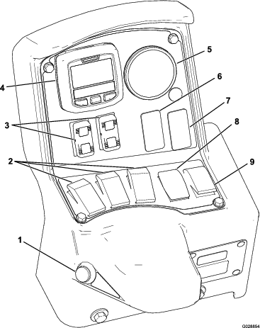
The InfoCenter LCD display shows information about your machine and battery pack such as the current battery charge, the speed, diagnostics information, and more (Figure 51). For more information, refer to Using the InfoCenter.
Master Section Switch
The master section switch (Figure 51) is located on the side of the console and to the right of the operator’s seat. It allows you to start or stop the spray operation. Press the switch to enable or disable the spray system.
Left, Center, and Right Section Switches
The left, center, and right section switches are located on the control panel (Figure 51). Toggle each switch forward to turn the corresponding section on and rearward to turn them off. When the switch is turned on, a light on the switch illuminates. These switches affect the spray system only when the master section switch is on.
Application-Rate Switch
The application-rate switch is located on the left side of the control panel (Figure 51). Press and hold the switch upward to increase the spray system application rate, or press and hold it downward to decrease application rate.
Boom-Section Lift Switches
The boom-section lift switches are located on the control panel and are used to raise the outer boom sections.
Sprayer-Mode Switch (HDX-Auto Model)
Use the sprayer-mode switch to select between the following spraying methods:
-
Use the manual mode when you want to manually control the sprayer application rate.
-
Use the automatic mode when you want the computer to control sprayer application rate with setting you enter in the InfoCenter.
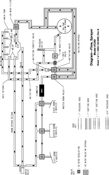
Regulating (Rate Control) Valve
The regulating valve located behind the tank (Figure 53), The regulating valve controls the amount of fluid that is routed to the section valves or the rate return to the tank.
Flow meter
The flow meter measures the flow rate of the fluid to the boom section valves (Figure 53).
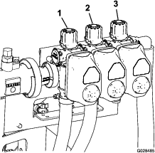
Section Valves
Use the boom-section valves to turn the sprayer pressure on or off to the sprayer nozzles in the left, center, and right boom sections (Figure 53).
Section-Bypass Valves
The boom section-bypass valves (Figure 54) redirect the fluid flow from a boom to the tank when you turn off the boom section. You can adjust these valves to ensure that the boom pressure remains constant no matter which combination of booms you are operating; refer to Calibrating the Section-Bypass Valves.
Agitation-Throttle Valve
This valve is located on the rear left side of the tank (Figure 55). Turn the knob on the valve to the 6 o'clock position to turn on the tank agitation and to the 8 o'clock position to turn off the tank agitation.
Note: HD-series models with a manual transmission—for agitation to work the PTO and clutch must be engaged and the engine must be running above an idle. If you stop the sprayer and need agitation circulating the content of the tank, place the range shift lever in the NEUTRAL position, let out the clutch, engage the parking brake, and set the hand throttle (if equipped).
Sprayer Pump
The sprayer pump is located at the rear of the machine (Figure 56).
Control the sprayer pump by performing the following:
-
For the HD-series model with a manual transmission—At the center console of the machine, move the PTO lever to the ENGAGE position to run the pump; move the PTO lever to the DISENGAGE position to stop the pump. Refer to the Workman HDX-Auto Utility Vehicle Operator’s Manual.
-
For the HDX-Auto model—At the dash panel to the left of the steering-wheel column, press the rocker switch for the high-flow hydraulic system up to the ON position to run the sprayer pump (the light of the rocker switch illuminates). Press the rocker switch down to the OFF position shut off the sprayer pump. Refer to the High-Flow Hydraulic Kit Installation Instructions (the light of the rocker switch shuts off).

Note: Specifications and design are subject to change without notice.
| Spray system base weight (vehicle weight not included) | 424 kg (935 lb) |
| Tank capacity | 757 L (200 US gallons) |
| Overall vehicle length with the standard spray system | 422 cm (166 inches) |
| Overall vehicle height with standard spray system to the top of the tank | 147 cm (58 inches) |
| Overall vehicle height with standard spray system and the booms stored in the X pattern | 234 cm (92 inches) |
| Overall vehicle width with the standard spray system and the booms stored in the X pattern | 175 cm (69 inches) |
Attachments/Accessories
A selection of Toro approved attachments and accessories is available for use with the machine to enhance and expand its capabilities. Contact your authorized Toro distributor.
To ensure optimum performance and continued safety certification of the machine, use only genuine Toro replacement parts and accessories. Replacement parts and accessories made by other manufacturers could be dangerous, and such use could void the product warranty.
Operation
Note: Determine the left and right sides of the machine from the normal operating position.
Note: If you need to transport the vehicle on a trailer with the sprayer installed, make sure that the booms are tied down and secure.
Before Operation
Before Operation Safety
General Safety
-
Never allow children or untrained people to operate or service the machine. Local regulations may restrict the age of the operator. The owner is responsible for training all operators and mechanics.
-
Become familiar with the safe operation of the equipment, operator controls, and safety signs.
-
Before you leave the operator’s position, do the following:
-
Park the machine on a level surface.
-
Shift the transmission into the NEUTRAL position (manual) or the PARK position (automatic).
-
Engage the parking brake.
-
Shut off the engine and remove the key (if equipped).
-
Wait for all movement to stop.
-
-
Know how to stop the machine and shut off the engine quickly.
-
Check that operator-presence controls, safety switches, and guards are attached and functioning properly. Do not operate the machine unless they are functioning properly.
-
If the machine does not function correctly or is damaged in any way, do not use the machine. Correct the problem before you operate the machine or attachment.
-
Ensure that all fluid line connectors are tight and that all hoses are in good condition before applying pressure to the system.
Chemical Safety
Chemical substances used in the sprayer system may be hazardous and toxic to you, bystanders, and animals, and they may damage plants, soil, and other property.
-
Read the information on each chemical. Refuse to operate or work on the sprayer if this information is not available.
-
Before working on a sprayer system, ensure that it has been neutralized and triple rinsed according to the recommendations of the chemical manufacturer(s) and that all the valves have been cycled 3 times.
-
Verify that there is an adequate supply of clean water and soap nearby, and immediately wash off any chemicals that contact you.
-
Carefully read and follow the chemical warning labels and safety data sheets (SDSs) for all chemicals used, and protect yourself according to the chemical manufacturer's recommendations.
-
Always protect your body while using chemicals. Use the appropriate personal protective equipment (PPE) to guard against contact with chemicals, such as the following:
-
safety glasses, goggles, and/or face shield
-
a chemical suit
-
a respirator or filter mask
-
chemical-resistant gloves
-
rubber boots or other substantial footwear
-
a clean change of clothes, soap, and disposable towels for cleanup
-
-
Obtain proper training before using or handling chemicals.
-
Use the correct chemical for the job.
-
Follow the chemical manufacturer's instructions for the safely applying the chemical. Do not exceed the recommended system application pressure.
-
Do not fill, calibrate, or clean the machine while people, especially children, or pets are in the area.
-
Handle chemicals in a well-ventilated area.
-
Do not eat, drink, or smoke while working near chemicals.
-
Do not clean spray nozzles by blowing through them or placing them in your mouth.
-
Always wash your hands and other exposed areas as soon as possible after working with chemicals.
-
Keep chemicals in their original packages and stored in a safe location.
-
Properly dispose of unused chemicals and chemical containers as instructed by the chemical manufacturer and your local codes.
-
Chemicals and fumes are dangerous; never enter the tank or place your head over or in the opening of a tank.
-
Follow all local, state, and federal regulations for spreading or spraying chemicals.
Using the InfoCenter
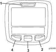
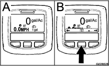
The InfoCenter LCD display shows information about your machine, such as the operating status, various diagnostics, and other information about the machine (Figure 57). There is a splash screen and main information screen on the InfoCenter. You can switch between the splash screen and main information screen, at any time, by pressing any of the InfoCenter buttons and then selecting the appropriate directional arrow.
-
Left button, Menu access/Back button—press this button to access the InfoCenter menus. You can also use it to back out of any menu you are currently using.
-
Middle button—use this button to scroll down menus.
-
Right button—use this button to open a menu where a right arrow indicated additional content.
Note: The purpose of each button may change depending on what function is active at the time. The LCD display shows an icon above each button that indicates its current function.
Starting the InfoCenter
-
Insert the key into the starter switch and rotate it to the ON position.
Note: The InfoCenter illuminates and displays the initialization screen (Figure 58).

-
After approximately 15 seconds, the home screen appears. Press the center selection button to display the information context (Figure 59).
Note: Rotating the starter switch to the START position and starting the engine causes the values indicated in the InfoCenter display to reflect the running machine.
Accessing the Settings Menu
-
Start the InfoCenter; refer toStarting the InfoCenter.
Note: The Home screen displays.
-
Press the center selection button to access the Information context.
Note: The information context icon displays.
-
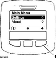
Press the center selection button to access the Main Menu (Figure 61).
-
Press the right selection button to display the Settings sub-menus.
Note: The Main Menu displays with the Settings option selected.
Note: Pressing the center selection button (the button below the down arrow icon in the display) moves the selected option down.
Changing the Units of Measure (English and Metric)
-
Access the Settings menu; refer to Accessing the Settings Menu.
-
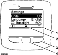
To change the unit of measure, press the right selection button to change the listed units of measure (Figure 62).
-
English: mph, gallons, and acre
-
Turf: mph, gallons, and 1,000 ft2
-
SI (metric): kph, liter, hectare
Note: The display switches between English, turf, and metric units.
Note: Pressing the left selection button saves your selection, exits the Settings menu, and returns to the Main Menu.
-
-
To change the language used in the display, press the center selection button (the button below the down arrow in the display) to move the selected option to Language (Figure 62).
-
Press the right selection button (the button below the list icon in the display) to highlight the listed language used in the display (Figure 62).
Note: Available languages include English, Spanish, French, German, Portuguese, Danish, Netherlands (Dutch), Finnish, Italian, Norwegian, and Swedish.
-
Press the left selection button to save your selection(s), exit the Settings menu, and return to the Main Menu (Figure 61).
-
Press the left selection button to return to the Home screen (Figure 62).
Adjusting the Backlighting and Contract Levels of the Display
-
Access the Settings menu; refer toAccessing the Settings Menu.
-
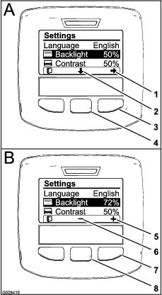
To adjust the backlight level of the display, press the center selection button (the button below the down arrow icon in the display) to move the selected option down to the Backlight setting (Figure 63).
-
Press the right selection button to display the value adjustment context (Figure 63).
Note: The display shows a (―) icon over the center selection button and a (+) icon over the right selection button.
-
Use the center selection button and right selection button to change the brightness level of the display (Figure 63).
Note: As you change the brightness value, the display changes the selected brightness level.
-
Press the left selection button (the button below the list icon in the display) to save your selection, exit the Backlight menu, and return to the Settings menu (Figure 63).
-
To adjust the contrast level of the display, press the center selection button (the button below the down arrow icon in the display) to move the selected option down to the Contrast setting (Figure 63).
-
Press the right selection button to display the value adjustment context (Figure 63).
Note: The display shows a (―) icon over the center selection button and a (+) icon over the right selection button.
-
Press the left selection button (the button below the list icon in the display) to save your selection, exit the Contrast menu, and return to the Settings menu (Figure 63).
-
Press the left selection button to exit the Settings menu and return to the Main Menu (Figure 61 and Figure 63).
-
Press the left selection button to return to the Home screen (Figure 63).
InfoCenter Icons
 | Information icon |
 | Next |
 | Previous |
 | Scroll down |
 | Enter |
 | Change the next value in the list |
 | Increase |
 | Decrease |
 | Active screen |
 | Inactive screen |
 | Go to the home screen |
 | Active home screen |
 | Save value |
 | Exit menu |
 | Hour meter |
 | Correct PIN code entered |
 | Check PIN entry/Calibration verification |
 | Master boom On/Boom sprayer Off |
 | Master boom On/Boom sprayer On |
 | Full spray tank |
 | Spray tank at half |
 | Tank level low |
 | Empty spray tank |
 or or  | TURF units (1,000 square feet) |
 | Area sprayed |
 | Volume sprayed |
 | Adjust tank volume |
 | Home screen |
 | Clear active area |
 | Clear all areas |
 | Adjust digit |
 | Select the next area for accumulation |
 | Application rate 1 |
 | Application rate 2 |
 | Boost rate |
Using the Menus
Access the calibration settings in the InfoCenter menu system by pressing the menu access button while at the main screen. This returns you to the main menu. Refer to the following tables for a summary of the options available from the menus:
| Calibration | |
| Menu Item | Description |
| Test Speed | This menu sets the test speed for calibration. |
| Flow Calibration | This menu calibrates the flow meter. |
| Speed Calibration | This menu calibrates the speed sensor. |
Selecting the Sprayer Programming
HDX-Auto Model
Switching between Manual Mode and Automatic Mode
-
At the control console, press the sprayer-mode switch to the left position to control the application rate of the sprayer through the InfoCenter in the AUTOMATIC MODE.
Note: An icon for the application rate appears in the display of the InfoCenter.
-
Press the sprayer-mode switch to the right to control the application rate of the sprayer by hand in the MANUAL MODE.
Note: When switching from the Automatic mode to the Manual mode, the icon for the application rate disappears from the display.
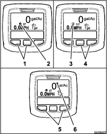
Switching between Sprayer Programming Settings
-
To select application rate 1, press the left 2 buttons of the InfoCenter (Figure 65).
Note: An icon
 appears.
 -
To select application rate 2 (application rate), press the right 2 buttons (Figure 65).
Note: An icon
 appears.
 -
To temporarily apply a boost application rate, press and hold the 2 outer buttons (Figure 65).
Note: An icon
 appears.
Note: The application rate boost is an additional percent above the active program (1 or 2) application rate. Press and hold the buttons to apply the boost application rate; release the buttons to stop the boost rate.
Programming the Application Rate and Application Rate Boost
HDX-Auto Model
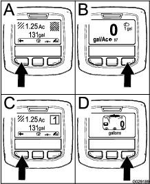
Programming the Application Rate 1 and 2
-
From the Home screen, press the center selection button to navigate to the Main Menu.
-
If needed, press the center selection button to highlight the application rate for sprayer program 1 (Figure 66).
Note: The icon for sprayer application rate 1 looks like the numeral 1 in a circle to the right of a bull's-eye target.
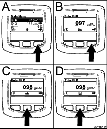
-
Press the right selection button to select sprayer program 1 (Figure 66A).
-
Set the numerical value by pressing the following selection buttons:
-
Once the right-most value is set, press the right selection button.
Note: The Save Icon appears above the center selection button (Figure 66D).
-
Press the center selection button (Figure 66D) to save the programming for application rate.
-
Press the center selection button to highlight the application rate for sprayer program 2.
Note: The icon for sprayer application rate 2 looks like the numeral 2 in a circle to the right of a bull's-eye target.
Note: You can use the application rate for sprayer program 2 to conveniently apply a higher or lower application rate to your turf site as needed.
-
Repeat steps 4 through 6.
Programming the Application Boost Rate
The application boost adds a specified percent to the active program application rate when the outer 2 buttons of the InfoCenter are pressed while spraying in Automatic mode.
-
From the Home screen, press the center selection button to navigate to the Main Menu.
-
If needed, press the center selection button to highlight the application rate boost (Figure 67).
Note: The icon for the application rate boost look 2 (+) signs to the right of a bull's-eye target (Figure 67).
-
Press the right selection button (Figure 67) to increase the boost percentage in 5% increments (20% maximum).
Using the Settings Menu
HDX-Auto Model
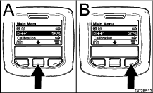
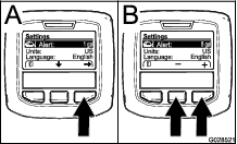
Selecting the Active Application Rate from the Settings Menu
-
From the Main Menu, press the center selection button to navigate to the Settings menu.
-
Press the center selection button to highlight the Active application rate setting (Figure 68).
-
Press the right selection button to toggle between application rate 1 and 2 (Figure 68).
-
Press the left selection button to save and return to the main menu
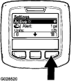
Setting the Tank-Level Alert
-
From the Main Menu, press the center selection button to navigate to the Settings menu.
-
Press the center selection button to highlight the Alert setting (Figure 69).
Note: The (-) and (+) icons appears above the center and right selection buttons.
-
Press the right selection button (Figure 69).
-
Use the center or right selection buttons to enter the minimum quantity in the tank when the alert displays during sprayer operation (Figure 69).
Note: Holding the button down increases the value of the tank alert by 10%.
-
Press the left selection button to save and return to the main menu
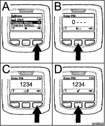
Entering the PIN into the InfoCenter
Note: Entering the PIN allows you to change the access protected settings and maintain the password.
Note: The factory entered PIN number is 1234.
-
From the Main Menu, press the center selection button to navigate to the Settings menu.
-
Press the center selection button to highlight the Protected Menus setting.
-
Press the right select button to select Protected Menus (Figure 70A).
-
Set the numerical value in the PIN entry screen by pressing the following selection buttons:
-
Once the right-most value is set, press the right selection button.
Note: The checkmark icon appears above the center selection button (Figure 70D).
-
Press the center selection button (Figure 70D) to enter the password.
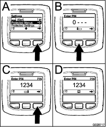
Changing the PIN
-
Enter the current PIN; refer to steps 1 through 6 in Entering the PIN into the InfoCenter.
-
From the Main Menu, press the center selection button to navigate to the Settings menu.
-
Press the center selection button to highlight the Protected Menus setting.
-
Press the right select button to select Protected Menus (Figure 71A).
-
Enter the new PIN into the entry screen by pressing the following selection buttons:
-
Once the right-most value is set, press the right selection button.
Note: The Save icon appears above the center selection button (Figure 71D).
-
Wait until the InfoCenter displays the “value saved message” and the red indicator light illuminates.
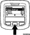
Setting the Protect Settings
Important: Use this function to lock and unlock the application rate.
Note: You must know the 4-digit PIN number to change settings for functions in the protected menus.
-
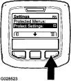
From the Main Menu, press the center selection button to navigate to the Settings menu.
-
Press the center selection button to highlight the Protect Settings entry.
Note: If there is no X in the box to the right of Protect Settings entry, the sub-menus for L Boom, C Boom, R Boom, and Reset Defaults are not locked with the PIN (Figure 73).
-
Press the right selection button.
Note: The PIN entry screen appears
-
Enter the PIN; refer to step 4 in Entering the PIN into the InfoCenter.
-
Once the right-most value is set, press the right selection button.
Note: The checkmark icon appears above the center selection button.
-
Press the center selection button.
Note: The sub-menus for L Boom, C Boom, R Boom, and Reset Defaults appears.
-
Press the center selection button to highlight the Protect Settings entry
-
Press the right selection button.
Note: An X appears in the box to the to the right of Protect Settings entry (Figure 73).
-
Wait until the InfoCenter displays the “value saved message” and the red indicator light illuminates.
Note: The sub-menus below the Protected Menus entry are locked with the PIN.
Note: To access the sub-menus, highlight the Protect Settings entry, press the right selection button, enter the PIN, and when the check-mark icon appears—press the center selection button.
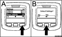
Resetting the Boom Section Sizes to Default
-
Press the center selection button to navigate to the Reset Default entry (Figure 74).
-
Press the right selection button to select Reset Default.
-
In the Default Settings screen, press the left selection button for NO or the right selection button for YES (Figure 74).
Note: Selecting YES restores the boom-section sizes to the factory setting.
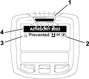
InfoCenter Advisories
Operator advisories automatically display on the InfoCenter screen when a machine function requires additional action. For example, if you attempt to start the engine while pressing the traction pedal, an advisory displays indicating that the traction pedal must be in the NEUTRAL position.
For each advisory that occurs, the fault indicator flashes, and an advisory code (number), an advisory description, and an advisory qualifier appears on the screen as shown in Figure 75.
Advisory descriptions and qualifiers appear as InfoCenter icons. Refer to InfoCenter Icons for a description of each icon.
Note: An advisory qualifier explains the conditions that triggered the advisory and provides instructions on eliminating the advisory.
Note: Advisories do not log into the fault log.
Note: You can clear an advisory from the display screen by pressing any of the InfoCenter keys.
Refer to the table that follows for the InfoCenter advisories:
| Advisory Code | Description |
|---|---|
| 200 | Start prevented—pump switch active |
| 201 | Start prevented—not in NEUTRAL |
| 202 | Start prevented—out of seat |
| 203 | Start prevented—throttle pedal is not home |
| 204 | Start prevented—starter engage timeout |
| 205 | Parking brake is engaged |
| 206 | Pump start prevented—boom active |
| 207 | Pump start prevented—engine speed high |
| 208 | Throttle/speed lock prevented—pump is not active |
| 209 | Throttle lock prevented—parking brake is not engaged |
| 210 | Speed lock prevented—operator not in seat or parking brake is engaged |
| 211 | Throttle/speed lock prevented—clutch or service brake is engaged |
| 212 | Tank low volume alert |
| 213 | Rinse pump ON |
| 220 | Flow sensor calibration |
| 221 | Flow sensor calibration—fill water in tank and enter volume filled |
| 222 | Flow sensor calibration—turn on the pump |
| 223 | Flow sensor calibration—turn on all the booms |
| 224 | Flow sensor calibration—calibration commenced |
| 225 | Flow sensor calibration—calibration complete |
| 226 | Flow sensor calibration—exiting calibration mode |
| 231 | Speed sensor calibration |
| 232 | Speed sensor calibration—fill the fresh-water tank, press next |
| 233 | Speed sensor calibration—fill the sprayer half full of water, press next |
| 234 | Speed sensor calibration—enter the calibration distance, press next |
| 235 | Speed sensor calibration—mark and drive the entered distance with sprayer sections off |
| 236 | Speed sensor calibration—speed sensor calibration in progress |
| 237 | Speed sensor calibration—speed sensor calibration complete |
| 238 | Speed sensor calibration—turn off the booms |
| 241 | Calibration out of bounds, using default |
Performing Pre-Starting Checks
Check the following items each time you begin use of the sprayer for the day:
-
Check the air pressure in the tires.
Note: The tires of this machine are different than car tires; they require less air pressure to minimize turf compaction and damage.
-
Check all fluid levels and add the appropriate amount of specified fluids, if any are found to be low.
-
Check the brake pedal operation.
-
Check to see that the lights are working.
-
Turn the steering wheel to the left and right to check steering response.
-
With the engine shut off, check for oil leaks, loose parts, and any other noticeable malfunctions.
If any of the above items are not correct, notify your mechanic or check with your supervisor before taking the sprayer out for the day. Your supervisor may want you to check other items daily, so ask what inspections you are responsible to perform.
Preparing the Sprayer
Selecting a Nozzle
Note: Refer to the nozzle-selection guide that is available through your authorized Toro distributor.
The turret bodies accepts up to 3 different nozzles.
-
Stop the sprayer on a level surface, shut off the engine, engage the parking brake, and remove the key.
-
Set the master section switch to the OFF position and set the spray-pump switch to the OFF position.
-
Rotate the turret of the nozzles in either direction to the correct nozzle.
-
Perform a flow calibration; refer to Calibrating the Sprayer Flow.
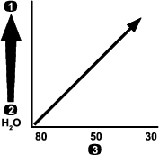
Selecting a Suction Filter
Standard Equipment: 50 mesh suction filter (blue)
Use the suction filter table to identify the screen mesh for the spray nozzles you are using based on chemicals products or solutions with a viscosity equivalent to water.
| Spray Nozzle Color Code (flow rate) | Screen Mesh Size* | Filter Color Code |
|---|---|---|
| Yellow (0.2 gpm) | 50 | Blue |
| Red (0.4 gpm) | 50 | Blue |
| Brown (0.5 gpm) | 50 (or 30) | Blue (or green) |
| Gray (0.6 gpm) | 30 | Green |
| White (0.8 gpm) | 30 | Green |
| Blue (1.0 gpm) | 30 | Green |
| Green (1.5 gpm) | 30 | Green |
| *The mesh size of the suction filters in this table are based on spray chemicals or solutions with the viscosity equivalent to water. | ||
Important: When you spray with higher viscosity (thicker) chemical products or solutions with wettable powders, you may need to use a coarser screen mesh for the optional suction filter; refer to Figure 76.
When you spray at a higher application rate, consider using a coarser optional suction-filter mesh; refer to Figure 77.

Selecting a Pressure Filter
Available screen sizes include:
Standard Equipment: 50 mesh suction filter (blue)
Use the pressure filter table to identify the screen mesh for the spray nozzles you are using based on chemicals products or solutions with a viscosity equivalent to water.
| Spray Nozzle Color Code (flow rate) | Screen Mesh Size* | Filter Color Code |
|---|---|---|
| As required for low viscosity chemicals or solutions or low application rates | 100 | Green |
| Yellow (0.2 gpm) | 80 | Yellow |
| Red (0.4 gpm) | 50 | Blue |
| Brown (0.5 gpm) | 50 | Blue |
| Gray (0.6 gpm) | 50 | Blue |
| White (0.8 gpm) | 50 | Blue |
| Blue (1.0 gpm) | 50 | Blue |
| Green (1.5 gpm) | 50 | Blue |
| As required for high viscosity chemicals or solutions or high application rates | 30 | Red |
| As required for high viscosity chemicals or solutions or high application rates | 16 | Brown |
| *The mesh size of the pressure filters in this table are based on spray chemicals or solutions with the viscosity equivalent to water. | ||
Important: When you spray with higher viscosity (thicker) chemical products or solutions with wettable powders, you may need to use a coarser screen mesh for the optional pressure-filter; refer to Figure 78.
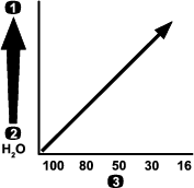
When you spray at a higher application rate, consider using a coarser optional pressure-filter mesh; refer to Figure 79.

Selecting a Nozzle-Tip Filter (Optional)
Note: The use the optional nozzle-tip filter to protect the spray-nozzle tip and increase its service life.
Use the nozzle-tip filter table to identify the screen mesh for the spray nozzles you are using based on chemicals products or solutions with a viscosity equivalent to water.
| Spray Nozzle Color Code (flow rate) | Filter Mesh Size* | Filter Color Code |
|---|---|---|
| Yellow (0.2 gpm) | 100 | Green |
| Red (0.4 gpm) | 50 | Blue |
| Brown (0.5 gpm) | 50 | Blue |
| Gray (0.6 gpm) | 50 | Blue |
| White (0.8 gpm) | 50 | Blue |
| Blue (1.0 gpm) | 50 | Blue |
| Green (1.5 gpm) | 50 | Blue |
| *The mesh size of the nozzle filters in this table are based on spray chemicals or solutions with the viscosity equivalent to water. | ||
Important: When you spray with higher viscosity (thicker) chemical products or solutions with wettable powders, you may need to use a coarser screen mesh for the optional tip-filter; refer to Figure 80.
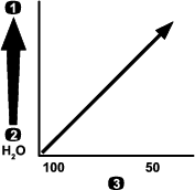
When you spray at a higher application rate, consider using a coarser tip-filter mesh; refer to Figure 81.

Filling the Tanks
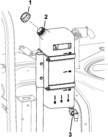
Filling the Freshwater Tank
Important: Do not use reclaimed water (gray water) in the freshwater tank.
Note: The freshwater tank is used to supply a source of fresh water for you to wash chemicals off your skin, eyes, or other surfaces in the case of accidental exposure.Always fill the freshwater tank with clean water before handling or mixing any chemicals.
The freshwater tank is located on the ROPS, behind the passenger seat (Figure 82). It supplies a source of fresh water for you to wash chemicals from your skin, eyes, or other surfaces in case of accidental exposure.
-
To fill the tank, unscrew the cap on the top of the tank and fill the tank with fresh water. Replace the cap.
-
To open the freshwater tank spigot, turn the lever on the spigot.
Filling the Spray Tank
Install the Chemical Pre-Mix Kit for optimal mixing and exterior tank cleanliness.
Important: Whenever possible, do not use reclaimed water (gray water) in the spray tank.
Important: Ensure that the chemicals you use are compatible for use with VitonTM (see the manufacturer's label; it should indicate if it is not compatible). Using a chemical that is not compatible with VitonTM degrades the O-rings in the sprayer, causing leaks.
Important: After filling the tank for the first time, check the tank straps for any play. Tighten them as necessary.
-
Purge the spray system of spray-system conditioner by running the sections.
-
Park the machine on a level surface, move the range selector to the neutral position, engage the parking brake, shut off the engine, and remove the key.
-
Ensure that the tank drain valve is closed.
-
Determine the amount of water needed to mix the amount of chemical you need as prescribed by the chemical manufacturer.
-
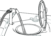
Open the tank cover on the spray tank.
Note: The tank lid is located at the center of the top of the tank. To open it, turn the front half of the cover counterclockwise and swing it open. You can remove the strainer inside for cleaning. To seal the tank, close the cover and rotate the front half clockwise.
-
Add 3/4 of the required water to the spray tank using the anti-siphon fill receptacle.
Important: Always use fresh, clean water in the spray tank. Do not pour concentrate into an empty tank.
-
Start the engine, engage the PTO, and set the hand throttle if equipped.
-
Turn the agitation switch ON position.
-
Add the proper amount of chemical concentrate to the tank, as directed by the chemical manufacturer.
Important: If you are using a wettable powder, mix the powder with a small amount of water to form a slurry before adding it to the tank
-
Add the remaining water to the tank.
Note: For better agitation, decrease the application rate setting.
Inspecting the Tank Straps
Important: Overtightening the tank strap fasteners can result in deforming and damaging the tank and straps.
-
Fill the main tank with water.
-
Check to see if there is any movement between the tank straps and the tank (Figure 84).
-
If the tank straps fit loose to the tank, tighten the flanged locknuts and bolts at the top of straps until the straps are flush with the surface of the tank (Figure 84).
Note: Do not overtighten the tank strap hardware.
Calibrating the Sprayer
Preparing the Machine
Important: Before calibrating the sprayer system used on the HDX-Auto model, fill the sprayer tank as required with clean water and operate the machine while spraying at 2.75 bar (40 psi) or greater for a minimum of 30 minutes.
Note: Before using the sprayer for the first time, if you change the nozzles, or as needed, calibrate the sprayer flow, speed, and section bypass.
-
Fill the spray tank with clean water.
Note: Ensure that there is enough water in the tank to complete each of the calibration procedures.
-
Lower the left and right boom sections.
-
For the HDX-Auto model—operate the machine while spraying at 2.75 bar (40 psi) or greater for a minimum of 30 minutes. Fill the sprayer tank with clean water when finished.
-
Set the protected settings to off; refer to Setting the Protect Settings.
-
For the HDX-Auto model—set the sprayer system to the Manual Mode; refer to Switching between Manual Mode and Automatic Mode.
Calibrating the Sprayer Flow
Operator supplied equipment: Stopwatch capable of measuring to ± 1/10 second and a container graduated in 50 ml (1 fl oz) increments.
Note: Calibrating the sprayer flow for machines without a throttle lock requires 2 people.
Preparing the Sprayer System
-
Set the transmission as follows:
-
For HD-Series Models with a manual transmission—shift the transmission to the NEUTRAL position.
-
For the HDX-Auto model—shift the transmission to P (park).
-
-
Engage the parking brake and start the engine.
-
Turn on the sprayer pump and turn on the agitation.
-
Press down on the accelerator pedal until the engine reaches maximum speed.
-
Set the engine speed as follows:
-
For machines without the optional throttle lock—have 1 person press down on the accelerator pedal until the engine reaches maximum speed.
Note: Have the other person collect samples from the sprayer nozzles.
-
For machines with the optional throttle lock, press down on the accelerator pedal until the engine reaches maximum speed and set the throttle lock; refer to operation instructions for your Workman hand throttle kit.
-
Performing a Catch Test
-
Set all 3 section switches and the master-section switch to the ON position.
-
Prepare to perform a catch test using the graduated container.
-
Start at 2.75 bar (40 psi) and use the application-rate switch to adjust the spray pressure so that a catch test yields the amounts listed in the table that follows.
Note: Collect 3 samples at 15 seconds each and average the quantities of water collected.
Nozzle Color Milliliters collected in 15 seconds Ounces collected in 15 seconds Yellow 189 6.4 Red 378 12.8 Brown 473 16.0 Gray 567 19.2 White 757 25.6 Blue 946 32.0 Green 1,419 48.0 -
Once the catch test has yielded the amounts listed in the table above, set the supervisor rate-lockout switch to the LOCK position.
-
Turn the master-section switch to the OFF position.
Setting the InfoCenter
-
On the InfoCenter, navigate to the Calibration menu and select FLOW CAL as follows:
Note: Selecting the Home Screen icon at any time cancels calibrations.
-
Press the center selection button on the InfoCenter twice to access the menus.
-
Enter the calibration menu by pressing the right selection button on the InfoCenter.
-
Select FLOW CAL by highlighting FLOW CAL and press the right selection button on the InfoCenter.
-
In the next screen, enter the known quantity of water that will be sprayed out of the sections for the calibration procedure; refer to the chart below.
-
Press the right selection button on the InfoCenter.
-
-
Using the plus (+) and minus (-) symbols, enter the flow volume according to the table below.
Nozzle Color Liters US Gallons Yellow 42 11 Red 83 22 Brown 106 28 Gray 125 33 White 167 44 Blue 208 55 Green 314 83 -
Turn on the master-section switch for 5 minutes.
Note: As the machine sprays, the InfoCenter displays the quantity of fluid that it is counting.
-
After spraying for 5 minutes, select the checkmark by pressing the center button on the InfoCenter.
Note: It is acceptable if the gallons displayed during the calibration process do not match the known quantity of water entered into the InfoCenter.
-
Shut off the master-section switch and select the checkmark by pressing the center button on the InfoCenter.
Note: Calibration is now complete.
Calibrating the Sprayer Speed
-
Ensure that the sprayer tank is filled with water.
-
On an open, flat area, mark off a distance between 45 to 152 m (150 to 500 ft).
Note: Mark off 152 m (500 ft) for more accurate results.
-
Start the engine and drive to the start of the marked-off distance.
Note: Align the center of the front tires with the starting line for the most accurate measurement.
-
On the InfoCenter, navigate to the Calibration menu and select Speed Calibration.
Note: Selecting the Home Screen icon at any time cancels the calibration.
-
Select the Next arrow (→) on the InfoCenter.
-
Using the plus (+) and minus (-) symbols, enter the marked-off distance into the InfoCenter.
-
Perform one of the following:
-
For HD-Series Models with a manual transmission—shift the machine into first gear and drive the marked distance in a straight line at full throttle.
-
For the HDX-Auto model,—shift the machine into D (drive) and drive the marked distance in a straight line at full throttle.
-
-
Stop the machine at the marked-off distance and select the checkmark on the InfoCenter.
Note: Slow down and roll to a stop to align the center of the front tires with the finish line, for the most accurate measurement.
Note: Calibration is now complete.
Calibrating the Section-Bypass Valves
Before using the sprayer for the first time, whenever you change the nozzles, or as needed, calibrate the sprayer flow, speed, and set the section bypass.
Important: Select an open flat area to perform this procedure.
Note: Calibrating the section bypass for machines without a throttle lock requires 2 people.
Preparing the Machine
-
Ensure that the sprayer tank is filled with water.
-
Set the transmission as follows:
-
For HD-Series Models with a manual transmission—shift the transmission to the NEUTRAL position.
-
For the HDX-Auto model—shift the transmission to P (park).
-
-
Engage the parking brake and turn the engine on.
-
Set the 3 section switches to the ON position, but leave the master-section switch in the OFF position.
-
Set the pump switch to the ON position, and turn on the agitation.
-
Set the engine speed as follows:
-
For machines without the optional throttle lock—have 1 person press down on the accelerator pedal until the engine reaches maximum engine speed.
Note: Have the other person adjust the section-bypass valves.
-
For machines with the optional throttle lock, press down on the accelerator pedal until the engine reaches maximum engine speed and set the throttle lock; refer to operation instructions for your Workman hand throttle kit.
-
-
On the InfoCenter, navigate to the Calibration menu and select Test Speed.
Note: Selecting the Home Screen icon at any time cancels calibration.
-
Using the plus (+) and minus (–) symbols, enter a test speed of 5.6 km/h (3.5 mph), then select the Home icon.
Adjusting the Section Bypass Valves
-
Using the application rate switch, adjust the application rate according to the table that follows.
Nozzle Application Rate Table
Nozzle Color SI (Metric) English Turf Yellow 159 L/ha 17 gpa 0.39 gpk Red 319 L/ha 34 gpa 0.78 gpk Brown 394 L/ha 42 gpa 0.96 gpk Gray 478 L/ha 51 gpa 1.17 gpk White 637 L/ha 68 gpa 1.56 gpk Blue 796 L/ha 85 gpa 1.95 gpk Green 1,190 L/ha 127 gpa 2.91 gpk -
Turn off the left-section switch and adjust the left section-bypass valve (Figure 85) until the pressure reading is at the previously adjusted level (typically 2.75 bar or 40 psi).
Note: The numbered indicators on the bypass valve are for reference only.
-
Turn on the left-section switch and turn off the right-section switch.
-
Adjust the right section-bypass valve (Figure 85) until the pressure reading is at the previously adjusted level (typically 2.75 bar or 40 psi).
-
Turn on the right-section switch and turn off the center-section switch.
-
Adjust the center section-bypass valve (Figure 85) until the pressure reading is at the previously adjusted level (typically 2.75 bar or 40 psi).
-
Turn all the section switched off.
-
Turn the spray pump off.
Note: Calibration is now complete.
Adjusting the Agitation and Master Bypass Valves
Agitation Bypass Valve Knob Positions
-
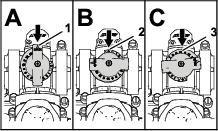
The agitation bypass valve is in the fully Open position as shown in Figure 86A.
-
The agitation bypass valve is in the Closed (0) position as shown in Figure 86B.
-
The agitation bypass valve is in an intermediate (adjusted relative to the pressure gauge for the sprayer system) position as shown in Figure 86C.
Calibrating the Agitation Bypass Valve
| Maintenance Service Interval | Maintenance Procedure |
|---|---|
| Yearly |
|
Important: Select an open flat area to perform this procedure.
Note: Calibrating the agitation bypass valve for machines without a throttle lock requires 2 people.
-
Ensure that the sprayer tank is filled with water.
-
Verify the agitation-control valve is open. If it has been adjusted, open it completely at this time.
-
Set the transmission as follows:
-
For HD-Series Models with a manual transmission—shift the transmission to the NEUTRAL position.
-
For the HDX-Auto model—shift the transmission to P (park).
-
-
Engage the parking brake and turn the engine on.
-
Turn on the sprayer pump.
-
Set the engine speed as follows:
-
For machines without the optional throttle lock—have 1 person press down on the accelerator pedal until the engine reaches maximum speed.
Note: Have the other person collect samples from the sprayer nozzles.
-
For machines with the optional throttle lock, press down on the accelerator pedal until the engine reaches maximum speed and set the throttle lock; refer to operation instructions for your Workman hand throttle kit.
-
-
Set the 3 individual section-valve switches to the OFF position.
-
Set the master-section switch to the ON position.
-
Set the system pressure to MAXIMUM.
-
Press the agitation switch to the OFF position and read the pressure gauge.
-
If the reading remains at 6.9 bar (100 psi) the agitation bypass valve is properly calibrated.
-
If the pressure gauge reads differently continue to the next step.
-
-
Adjust the agitation bypass valve (Figure 87) on the backside of the agitation valve until the pressure reading on the gauge is 6.9 bar (100 psi).
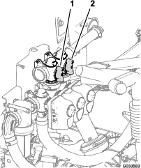
-
Press the pump switch to the OFF position, shift the throttle lever to the IDLE position, and turn the starter switch to the OFF position.
Adjusting the Master Section-Bypass Valve
Note: Adjusting the master section-bypass valve reduces or increases the amount of flow sent to the agitation nozzles in the tank when the master boom switch is set to the OFF position.
-
Ensure that the sprayer tank is filled with water.
-
Engage the parking brake.
-
Set the transmission as follows:
-
For HD-Series Models with a manual transmission—shift the transmission to the NEUTRAL position.
-
For the HDX-Auto model—shift the transmission to P (park).
-
-
Turn on the sprayer pump.
-
Set the agitation switch to the ON position.
-
Set the master-section switch to the OFF position.
-
Set the engine speed as follows:
-
For machines without the optional throttle lock—have 1 person press down on the accelerator pedal until the engine reaches maximum speed.
Note: Have the other person collect samples from the sprayer nozzles.
-
For machines with the optional throttle lock, press down on the accelerator pedal until the engine reaches maximum speed and set the throttle lock; refer to operation instructions for your Workman hand throttle kit.
-
-
Adjust the master section-bypass handle to control the amount of agitation occurring in the tank (Figure 87).
-
Reduce the throttle speed to idle.
-
Set the agitation switch and pump switch to the OFF position.
-
Shut off the engine.
Locating the Spray Pump
The spray pump is located at the back of the machine (Figure 88).
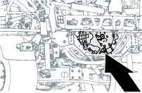
During Operation
During Operation Safety
General Safety
-
The owner/operator can prevent and is responsible for accidents that may cause personal injury or property damage.
-
Wear appropriate clothing, including eye protection; long pants; substantial, slip-resistant footwear; and hearing protection. Tie back long hair and do not wear loose clothing or loose jewelry.
-
Wear appropriate personal protective equipment as directed in Chemical Safety.
-
Use your full attention while operating the machine. Do not engage in any activity that causes distractions; otherwise, injury or property damage may occur.
-
Do not operate the machine while ill, tired, or under the influence of alcohol or drugs.
-
Do not carry more than 1 passenger on the machine; the passenger should sit in the designated seating position only.
-
Operate the machine only in good visibility. Avoid holes or hidden hazards.
-
Before you start the engine, ensure that you are in the operating position, the transmission is in the NEUTRAL position (manual) or the PARK position (automatic), and the parking brake is engaged.
-
Remain seated whenever the machine is in motion. Keep both hands on the steering wheel whenever possible, and always keep your arms and legs within the operator’s compartment.
-
Use care when approaching blind corners, shrubs, trees, or other objects that may obscure your vision.
-
Before backing up, look rearward and ensure that no one is behind you. Back up slowly.
-
Never spray while people, especially children, or pets are nearby.
-
Do not operate the machine near drop-offs, ditches, or embankments. The machine could suddenly roll over if a wheel goes over the edge or if the edge gives way.
-
Reduce the speed when operating on rough terrain, uneven ground, and near curbs, holes, and other sudden changes in terrain. Loads may shift, causing the machine to become unstable.
-
Stop the machine, shut off the engine, remove the key, engage the parking brake, and inspect for damage after striking an object or if there is an abnormal vibration in the machine. Make all necessary repairs before resuming operation.
-
Slow down and use caution when making turns and crossing roads and sidewalks with the machine. Always yield the right-of-way.
-
Use extra caution when operating the machine on wet surfaces, in adverse weather conditions, at higher speeds, or with a full load. Stopping time and distance increase in these conditions.
-
Do not touch the engine or muffler while the engine is running or soon after it has shut off. These areas may be hot enough to cause burns.
-
Before you leave the operator’s position, do the following:
-
Park the machine on a level surface.
-
Shift the transmission into the NEUTRAL position (manual) or the PARK position (automatic).
-
Shut off the spray pump.
-
Engage the parking brake.
-
Shut off the engine and remove the key (if equipped).
-
Wait for all movement to stop.
-
-
Never run an engine in an area where exhaust gasses are enclosed.
-
Do not operate the machine when there is the risk of lightning.
-
Use accessories and attachments approved by Toro only.
Operating the Sprayer
To operate the Multi Pro WM, first fill the spray tank, then apply the solution to the work area, and finally clean the tank. It is important that you complete all 3 of these steps in succession to avoid damaging the sprayer. For example, do not mix and add chemicals in the spray tank at night and then spray in the morning. This would cause the chemicals to separate and possibly damage the sprayer components.
Important: The tank markings are for reference only and cannot be considered accurate for calibration.
Caution
Chemicals are hazardous and can cause personal injury.
-
Read the directions on the chemical labels before handling the chemicals, and follow all manufacturer recommendations and precautions.
-
Keep chemicals away from your skin. Should contact occur, wash the affected area thoroughly with soap and clean water.
-
Wear goggles and any other protective equipment recommended by the chemical manufacturer.
The Multi Pro WM has been specifically designed to have high durability to give it the long sprayer life you need. Different materials have been chosen for specific reasons at different locations on your sprayer to meet this goal. Unfortunately, there is no single material which is perfect for all foreseeable applications.
Some chemicals are more aggressive than others and each chemical interacts differently with various materials. Some consistencies (e.g., wettable powders, charcoal) are more abrasive and lead to higher wear rates. If a chemical is available in a formulation that would provide increased life to the sprayer, use this alternative formulation.
As always, remember to clean your machine and spray system thoroughly after all applications. This ensures that your sprayer has a long and trouble-free life.
Spraying
Using the Sprayer
Important: To ensure that your solution remains well mixed, use the agitation feature whenever you have solution in the tank. For agitation to work, you must engage the PTO and the engine must be running above an idle. If you stop the vehicle and need the agitation on, place the shift lever in the NEUTRAL position, engage the parking brake, engage the PTO, engage the clutch, and set the hand throttle, if equipped.
Note: This procedure assumes that the PTO is engaged (HD-series models with a manual transmission) and the section valve calibration is complete.
-
Lower the booms into position.
-
For the HDX-Auto model, set the sprayer-mode switch as following:
-
When using the sprayer in the MANUAL MODE press the switch to the right; refer to Sprayer-Mode Switch (HDX-Auto Model).
-
When using the sprayer in the AUTOMATIC MODE press the switch to the left.
-
-
Set the master-section switch to the OFF position.
-
Set the individual section switches, as needed, to the ON positions.
-
Drive to the location where you plan to spray.
-
Navigate to the Application Rate screen on the InfoCenter and set the desired rate by performing the following steps:
-
Ensure that the switch for the pump is in the ON position.
-
For HD-series models with a manual transmission, select the desired gear range.
-
Begin driving at your target ground speed.
-
For HD-series models with a manual transmission or with an automatic transmission used in the manual mode, verify that the monitor displays the correct application rate. If needed, adjust the application-rate switch until the monitor displays the desired application rate.
Note: For HD-series models with an automatic transmission that are operated in the automatic mode, the computer automatically adjusts the sprayer pressure to maintain the application rate.
-
Return to the location where you are spraying.
-
-
Set the master-section switch to the ON position and begin spraying.
Note: When the tank is nearly empty, the agitation may cause foaming in the tank. To prevent this, turn the agitation valve off. Alternatively, you can use an anti-foaming agent in the tank.
-
When finished spraying, set the master-section switch to the OFF position to turn off all spay sections, and disengage the PTO lever (HD-series models with a manual transmission).
Turf Care Precautions while Operating in Stationary Modes
Important: Under some conditions, heat from the engine, radiator, and muffler can potentially damage grass when operating the sprayer in a stationary mode. Stationary modes include tank agitation, hand spraying with a spray gun, or using a walking boom.
Use the following precautions:
-
Avoid stationary spraying when conditions are extremely hot and/or dry, as turf can be more stressed during these periods.
-
Avoid parking on the turf while stationary spraying. Park on a cart path whenever possible.
-
Minimize the amount of time that you leave the machine running over any particular area of turf. The extent of damage to the grass depends on both time and temperature.
-
Set the engine speed as low as possible to achieve the desired pressure and flow. This minimizes the heat generated and the air velocity from the cooling fan.
-
Allow the heat to escape upward from the engine compartment by raising the seat assemblies during stationary operation rather than being forced out under the vehicle.
Positioning the Spray Sections
The boom-section lift switches on the sprayer control panel allows you to move the outer spray sections between transport position and spray position without leaving the operator's seat. Whenever possible, stop the machine before changing spray section positions.
Setting the Hydraulic Lift Lock
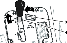
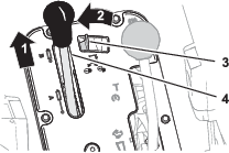
Changing the Spray Section Position
Perform the following steps to move the outer spray sections to the SPRAY position:
-
Park the machine on a level surface.
-
Use the boom-section lift switches to lower the outer sections.
Note: Wait until the outer spray sections reach the full, extended spray position.
Complete the sprayer job, then perform the following steps to retract the outer spray sections into the transport position:
-
Park the machine on a level surface.
-
Use the boom-section lift switches to raise the outer spray sections, until they have moved completely into boom-section transport cradles forming the “X” transport position, and the lift cylinders are fully retracted.
Important: Release the boom-section lift switch(es) once the outer spray sections have reached the desired position. Running the actuators against the mechanical stops may damage the lift cylinders and/or other hydraulic components.
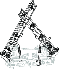
Important: To prevent damage to the lift cylinder, make sure that the actuators are fully retracted before transporting the machine.
Using the Boom-Section Transport Cradle
The sprayer is equipped with boom-section transport cradles that have a unique safety feature. In the event the spray section accidentally contacts with a low overhead object while in the transport position, you can push the spray section(s) out of the transport cradles. If this occurs, the spray sections come to rest in a near horizontal position to the rear of the machine. While this movement will not damage the spray sections, they should be immediately positioned into the transport cradle.
Important: The spray sections can be damaged by transporting them in any position other than the “X” transport position using the boom transport cradle.
To put the outer spray sections back into the transport cradle, lower the spray section(s) to the spray position and then raise the spray section(s) back to the transport position. Make sure that the lift cylinders are fully retracted to prevent damaging the actuator rod.
Spraying Tips
-
Do not overlap areas where you have previously sprayed.
-
Watch for plugged nozzles. Replace all worn or damaged nozzles.
-
Use the master-section switch to stop the spray flow before stopping the sprayer. Once stopped, use the neutral engine speed lock to hold the engine speed up to keep the agitation running.
-
You obtain better results if the sprayer is moving when you turn the spray sections on.
-
Watch for changes in the application rate that may indicate that your speed has changed beyond the range of the nozzles or there is a problem with the spray system.
HD-Series Models with an Automatic Transmission Operated in the Automatic Mode
Note: Refer to the nozzle selection guide that is available through your authorized Toro distributor.
-
If you are operating the sprayer at a slow ground speed that causes the computer to maintain too low of a sprayer system pressure for the application rating of the selected nozzles, the chemical solution discharges from the nozzle incorrectly (running or dribbling). Select a sprayer nozzle with a lower application rate range.
-
If you are operating the sprayer at a high ground speed that causes the computer to use full sprayer system pressure and the sprayer pressure is inadequate to achieve the desired application rate. To correct the application rate, slow your ground speed to achieve your application rate or select a sprayer nozzle with a higher application rate range.
Unclogging a Nozzle
If a nozzle becomes clogged while you are spraying, clean the nozzle as follows:
-
Stop the sprayer on a level surface, shut off the engine, and engage the parking brake.
-
Set the master section switch to the OFF position and then set the sprayer-pump switch to the OFF position.
-
Remove the clogged nozzle and clean it using a spray bottle of water and a toothbrush.
-
Install the nozzle.
After Operation
After Operation Safety
-
Park the machine on a level surface; engage the parking brake; shut off the engine; remove the key; and wait for all movement to stop before leaving the machine.
-
After you finish operating the machine for the day, wash off all chemical residue from the outside of the machine; refer to Chemical Safety.
-
Allow the engine to cool before storing the machine in any enclosure.
-
Maintain and clean the seat belt(s) as necessary.
-
Never store the machine or fuel container where there is an open flame, spark, or pilot light, such as on a water heater or other appliance.
-
Keep all parts of the machine in good working condition and all hardware tightened.
-
Replace all worn, damaged, or missing decals.
Cleaning the Sprayer System
Important: Do not use brackish or reclaimed water to clean the machine.
Draining the Sprayer Tank
-
Park the machine on a level surface, engage the parking brake, shut off the engine, and remove the key.
-
Locate the tank drain valve on the right side of the machine (Figure 92).
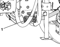
-
Open the valve to drain all unused material from the tank (Figure 93).
Important: Dispose of all waste chemicals according to local codes and the material manufacturer's instructions.
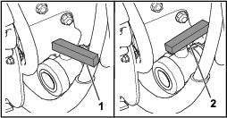
-
Close the drain valve (Figure 93).
Cleaning the Sprayer
| Maintenance Service Interval | Maintenance Procedure |
|---|---|
| Yearly |
|
Important: You must always empty and clean the sprayer immediately after each use. Failure to do so may cause the chemicals to dry or thicken in the lines, clogging the pump and other components.
Use the approved rinse kit for this machine. Contact your authorized Toro distributor for more information.
Clean the spray system after each spraying session. To thoroughly clean the spray system, do the following:
-
Use 3 separate rinses.
-
Use the cleaners and neutralizers as recommended by the chemical manufacturers.
-
Use pure clean water (no cleaners or neutralizers) for the last rinse.
-
Fill the tank with at least 190 L (50 US gallons) of clean fresh water and close the cover.
Note: You can use a cleaning/neutralizing agent in the water as needed. On the final rinse, use only clean, clear water.
-
Lower the booms into the spray position.
-
Start the engine and set the pump switch to the ON position.
-
Move the throttle to a higher idle.
-
Ensure that the agitation switch is in the ON position and use the application-rate switch to increase the pressure to a high setting.
-
Set the master-section switch and individual section switches to the ON positions to begin spraying.
-
Allow all the water in the tank to spray out though the nozzles.
-
Check the nozzles to ensure that they are all spraying correctly.
-
Set the master-section switch to the OFF position, shut off the sprayer pump, and shut off the engine.
-
Repeat steps 1 through 9 at least 2 more times to ensure that the spray system is fully cleaned.
Important: You must always complete this procedure at least 3 times to ensure that the spray system is fully clean, preventing damage to the system.
-
Clean the suction filter and pressure filter; refer to Cleaning the Suction Filter and Cleaning the Pressure Filter.
Important: If you used wettable powder chemicals, clean the strainer after each tank.
-
Using a garden hose, rinse off the outside of the sprayer with clean water.
-
Remove the nozzles and clean them by hand. Replace damaged or worn nozzles.
Cleaning the Suction Filter
| Maintenance Service Interval | Maintenance Procedure |
|---|---|
| Before each use or daily |
|
-
Park the machine on a level surface, engage the parking brake, shut off the pump, shut off the engine, and remove the key.
-
At the top of the sprayer tank, remove the retainer that secures the hose fitting attached to the large hose from the filter housing (Figure 94).
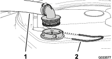
-
Remove the hose and hose fitting from the filter housing (Figure 94).
-
Pull the suction strainer out of the filter housing in the tank (Figure 95).
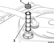
-
Clean the suction filter with clean water.
Important: Replace the filter if it is damaged or cannot be cleaned.
-
Insert the suction filter into the filter housing until the filter is fully seated.
-
Align the hose and hose fitting to the filter housing at the top of the tank, and secure fitting and housing with the retainer that you removed in step 2.
Cleaning the Pressure Filter
| Maintenance Service Interval | Maintenance Procedure |
|---|---|
| Before each use or daily |
|
-
Park the machine on a level surface, engage the parking brake, shut off the sprayer pump, shut off the engine, and remove the key.
-
Align a drain pan under the pressure filter (Figure 96).
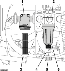
-
Rotate the drain cap counterclockwise and remove it from the bowl of the pressure filter (Figure 96).
Note: Allow the bowl to drain completely.
-
Rotate the bowl counterclockwise and remove the filter head (Figure 96).
-
Remove the pressure filter element (Figure 96).
-
Clean the pressure filter element with clean water.
Important: Replace the filter if it is damaged or cannot be cleaned.
-
Check the gasket for the drain plug (located inside the bowl) and the gasket for bowl (located inside the filter head) for damage and wear (Figure 96).
Important: Replace any damaged or worn gaskets for the plug, bowl, or both.
-
Install the pressure filter element into the filter head (Figure 96).
Note: Ensure that the filter element is firmly seated into the filter head.
-
Install the bowl onto the filter head, and tighten by hand (Figure 96).
-
Assemble the drain cap onto the fitting at the bottom of the bowl, and tighten the cap by hand (Figure 96).
Cleaning the Nozzle Filter
-
Park the machine on a level surface, engage the parking brake, shut off the sprayer pump, shut off the engine, and remove the key.
-
Remove the nozzle from the spray turret (Figure 97).
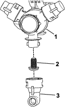
-
Remove the nozzle filter (Figure 97).
-
Clean the nozzle filter with clean water.
Important: Replace the filter if it is damaged or cannot be cleaned.
-
Install the nozzle filter (Figure 97).
Note: Ensure that the filter is fully seated.
-
Install the nozzle onto the spray turret (Figure 97).
Conditioning the Spray System
| Maintenance Service Interval | Maintenance Procedure |
|---|---|
| After each use |
|
Conditioner Specification
Conditioner specification: propylene glycol "non-toxic RV antifreeze” with corrosion inhibitor
Important: Use only propylene glycol with corrosion inhibitor. Do not use recycled propylene glycol. Do not use ethylene glycol base antifreeze.Do not use propylene glycol with soluble alcohols (methanol, ethanol, or isopropanol) or brines added.
Preparing the Conditioner
-
Move the machine to a level surface, set the parking brake, shut off the engine, and remove the key.
-
Add conditioner to the tank as follows:
-
For ready to use (premixed) propylene glycol RV antifreeze—add 10 gallons of propylene glycol RV antifreeze to the tank.
-
For concentrated propylene glycol RV antifreeze, perform the following steps:
-
Add a 10 gallon mixture of propylene glycol RV antifreeze and water into the sprayer tank. Prepared the antifreeze mixture as instructed manufacturer for a concentration rated for -45°C (-50°F) minimum.
Important: Use only clean water when cleaning the sprayer.
-
Start the engine and set the spray-pump switch to the ON position.
-
Press the accelerator pedal to increase the engine speed.
-
Set the agitation switch to the ON position.
Allow the conditioner and water solution to circulate for 3 minutes or longer.
-
-
Spraying the Conditioner
Recommended tool: a clear catch container.
-
Move the machine to the drain pad area and set the parking brake.
-
Lower the outer booms sections.
-
Set the left, center, and right section switches and the master section switch to the ON position.
-
Allow the spray system to spray until the nozzles discharge the conditioner.
Note: Most propylene glycol RV antifreeze is colored pink. Use the catch container to sample the sprayer discharge at several of the nozzles.
-
Shut off the master section switch, 3 section switches, agitation switch, spray-pump switch, engine, and remove the key.
Transporting or Towing the Machine
For information on transporting or towing the machine, refer to the Operator's Manual for your Workman vehicle.
Important: Tie outer spray sections to the boom-section transport cradles.
Maintenance
Note: Download a free copy of the electrical or hydraulic schematic by visiting www.Toro.com and searching for your machine from the Manuals link on the home page.
Note: Determine the left and right sides of the machine from the normal operating position.
Maintenance Safety
-
Before you leave the operator’s position, do the following:
-
Park the machine on a level surface.
-
Shift the transmission into the NEUTRAL position (manual) or the PARK position (automatic).
-
Engage the parking brake.
-
Shut off the engine and remove the key (if equipped).
-
Wait for all movement to stop.
-
-
Allow machine components to cool before performing maintenance.
-
Allow only qualified and authorized personnel to maintain, repair, adjust, or inspect the machine.
-
Before performing any maintenance, thoroughly clean and rinse the sprayer; refer to Chemical Safety.
-
Chemicals used in the sprayer system may be hazardous and toxic to you, bystanders, animals, plants, soils, or other property.
-
Carefully read and follow the chemical warning labels and safety data sheets (SDSs) for all chemicals used, and protect yourself according to the chemical manufacturer’s recommendations.
-
Always protect your skin while you are near chemicals. Use the appropriate personal protective equipment (PPE) to guard against contact with chemicals, including the following:
-
safety glasses, goggles, and/or face shield
-
a chemical suit
-
a respirator or filter mask
-
chemical-resistant gloves
-
rubber boots or other substantial footwear
-
a clean change of clothes, soap, and disposable towels for cleanup
-
-
Refuse to operate or work on the sprayer if chemical safety information is not available.
-
Do not fill, calibrate, or clean the machine while people, especially children, or pets are in the area.
-
Handle chemicals in a well-ventilated area.
-
Have clean water available, especially when filling the spray tank.
-
Do not eat, drink, or smoke while working near chemicals.
-
Do not clean spray nozzles by blowing through them or placing them in your mouth.
-
Always wash your hands and other exposed areas as soon as possible after working with chemicals.
-
Chemicals and fumes are dangerous; never enter the tank or place your head over or in the opening of a tank.
-
-
To ensure that the entire machine is in good condition, keep all hardware properly tightened.
-
To reduce the potential for fire, keep the engine area free of excessive grease, chemicals, grass, leaves, and dirt.
-
If you must run the engine to perform a maintenance adjustment, keep your hands, feet, clothing, and any parts of your body away from the engine and any moving parts. Keep everyone away.
-
Do not adjust the ground speed of the machine. To ensure safety and accuracy, have an authorized Toro distributor check the ground speed.
-
If the machine requires a major repair or you need technical help, contact an authorized Toro distributor.
-
Modifying this machine in any manner may affect machine operation, performance, durability, or its use, and result in injury or death. Such use could void the product warranty.
-
Support the machine with jack stands whenever you work under the machine.
-
Carefully release pressure from components with stored energy.
Recommended Maintenance Schedule(s)
| Maintenance Service Interval | Maintenance Procedure |
|---|---|
| Before each use or daily |
|
| After each use |
|
| Every 50 hours |
|
| Every 100 hours |
|
| Every 200 hours |
|
| Every 400 hours |
|
| Yearly |
|
Important: Refer to the Operator's Manual for your machine and the engine owner’s manual for additional maintenance procedures.
Notation for Areas of Concern
| Inspection performed by: | ||
| Item | Date | Information |
| 1 | ||
| 2 | ||
| 3 | ||
| 4 | ||
| 5 | ||
| 6 | ||
| 7 | ||
| 8 | ||
| 9 | ||
| 10 | ||
Pre-Maintenance Procedures
Caution
If you leave the key in the starter switch, someone could accidently start the engine and seriously injure you or bystanders.
Remove the key from the starter switch and disconnect the negative battery cable from the battery before you do any maintenance. Set the battery cable aside so that it does not accidentally contact the battery post.
Accessing the Machine
Raising the Tank Assembly
Danger
The sprayer tank assembly represents a stored energy hazard. If not properly retained when installing or removing the assembly, it can move or fall and injure you or other bystanders.
Use straps and an overhead lift to support the sprayer tank assembly during installation, removal, or any maintenance whenever you remove the retaining fasteners.
You can raise up the tank assembly to access to the engine and other internal components. Pivot the boom extension forward to distribute the weight more evenly.
-
Empty the spray tank.
-
Park the vehicle on a level surface.
-
Use the boom-control switches to raise the boom extension to approximately 45°.
-
Engage the parking brake, shut off the engine, and remove the key.
-
Remove the safety bolts from the front of the skid (Figure 98).
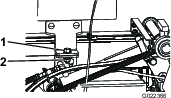
-
Fold the boom extensions forward, alongside the tank assembly to distribute the weight more evenly, and keep it from tipping backward.
-
Raise the tank assembly until the lift cylinders are fully extended.
-
Remove the bed support from the storage brackets at back of the ROPS panel (Figure 99).
-
Push the bed support onto the cylinder rod, making sure that the support end tabs rest on the end of cylinder barrel and on the rod end of the lift cylinder (Figure 100).
Lowering the Tank Assembly
-
When you are ready to lower the tank assembly, remove the bed support from the cylinder and insert it into the brackets on the back of the ROPS panel.
Important: Do not try to lower the tank assembly with the bed safety support on the cylinder.
-
Retract the lift cylinders to carefully lower the tank to the frame.
-
Install the 2 hold down bolts and fasteners to secure the tank assembly.
-
Fold the boom extensions rearward to the extended position.
-
Use the boom-control switches to raise the boom extensions to the TRANSPORT position.
Lubrication
Greasing the Sprayer Pump
| Maintenance Service Interval | Maintenance Procedure |
|---|---|
| Every 50 hours |
|
Grease Type: Mobil XHP 461
-
Locate the grease fittings on the sprayer pump.
Note: The pump is located at the rear end of the machine.
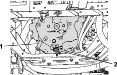
-
Wipe the 2 remote grease fittings clean.
-
Pump grease into each remote grease fitting.
-
Wipe off the excess grease.
Greasing the Boom Hinges
| Maintenance Service Interval | Maintenance Procedure |
|---|---|
| Every 100 hours |
|
Important: If you wash the boom hinge with water, clear all water and debris from the hinge assembly and apply fresh grease.
Grease Type: No. 2 lithium grease
-
Wipe the grease fittings clean so that foreign matter cannot be forced into the bearing or bushing.
-
Pump grease into the bearing or bushing at each fitting Figure 102.
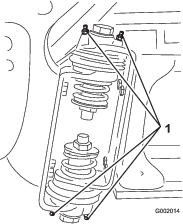
-
Wipe off excess grease.
-
Repeat this procedure for each boom pivot.
Electrical System Maintenance
Electrical System Safety
-
Disconnect the battery before repairing the machine. Disconnect the negative terminal first and the positive last. Connect the positive terminal first and the negative last.
-
Charge the battery in an open, well-ventilated area, away from sparks and flames. Unplug the charger before connecting or disconnecting the battery.
-
Wear protective clothing and use insulated tools.
Replacing the Fuses
The sprayer system fuse block is mounted to the end of the fuse block for the vehicle. Replace an open fuse with a fuse of the same type and amperage.
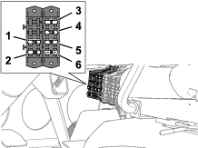
Spray System Maintenance
Inspecting the Hoses
| Maintenance Service Interval | Maintenance Procedure |
|---|---|
| Every 200 hours |
|
| Every 400 hours |
|
Examine each hose in the spray system for cracks, leaks, or other damage. At the same time, inspect the connections and fittings for similar damage. Replace any hoses and fittings if they are damaged.
Changing the Suction Filter
| Maintenance Service Interval | Maintenance Procedure |
|---|---|
| Every 400 hours |
|
Note: Determine the appropriate suction filter mesh size that you need for your job; refer to Selecting a Suction Filter.
-
Park the machine on a level surface, engage the parking brake, shut off the pump, shut off the engine, and remove the key.
-
At the top of the sprayer tank, remove the retainer that secures the hose fitting attached to the large hose from the filter housing (Figure 104).
-
Remove the hose and hose fitting from the filter housing (Figure 104).
-
Remove the old suction filter from the filter housing in the tank (Figure 105).
Note: Discard the old filter.
-
Install the new suction filter into the filter housing.
Note: Ensure that the filter is fully seated.
-
Align the hose and hose fitting to the filter housing at the top of the tank, and secure the fitting and housing with the retainer that you removed in step 2.
Changing the Pressure Filter
| Maintenance Service Interval | Maintenance Procedure |
|---|---|
| Every 400 hours |
|
Note: Determine the appropriate pressure filter mesh size that you need for your job; refer to Selecting a Pressure Filter.
-
Park the machine on a level surface, engage the parking brake, shut off the sprayer pump, shut off the engine, and remove the key.
-
Align a drain pan under the pressure filter (Figure 106).
-
Rotate the drain cap counterclockwise and remove it from the bowl of the pressure filter (Figure 106).
Note: Allow the bowl to drain completely.
-
Rotate the bowl counterclockwise and remove the filter head (Figure 106).
-
Remove the old pressure filter element (Figure 106).
Note: Discard the old filter.
-
Check the gasket for the drain plug (located inside the bowl) and the gasket for bowl (located inside the filter head) for damage and wear (Figure 106).
Note: Replace any damaged or worn gaskets for the plug, bowl, or both.
-
Install the new pressure filter element into the filter head (Figure 106).
Note: Ensure that the filter element is firmly seated into the filter head.
-
Install the bowl onto the filter head, and tighten by hand (Figure 106).
-
Assemble the drain cap onto the fitting at the bottom of the bowl, and tighten the cap by hand (Figure 106).
Changing the Nozzle Filter
Note: Determine the appropriate nozzle filter mesh size that you need for your job; refer to Selecting a Nozzle-Tip Filter (Optional).
-
Park the machine on a level surface, engage the parking brake, shut off the sprayer pump, shut off the engine, and remove the key.
-
Remove the nozzle from the spray turret (Figure 107).
-
Remove the old nozzle filter (Figure 107).
Note: Discard the old filter.
-
Install the new nozzle filter (Figure 107).
Note: Ensure that the filter is fully seated.
-
Install the nozzle onto the spray turret (Figure 107).
Inspecting the Sprayer Pump
| Maintenance Service Interval | Maintenance Procedure |
|---|---|
| Every 400 hours |
|
Note: The following machine components are considered parts subject to consumption through use unless found defective and are not covered by the Warranty associated with this machine.
Have an authorized Toro distributor check the following internal pump components for damage:
-
Pump diaphragm
-
Pump check valve assemblies
Replace any components if necessary.
Inspecting the Nylon Pivot Bushings
| Maintenance Service Interval | Maintenance Procedure |
|---|---|
| Every 400 hours |
|
-
Park the machine on a level surface, engage the parking brake, shut off the pump, shut off the engine, and remove the key.
-
Extend the outer-boom sections to the spray position and support the boom sections using stands or straps and lifting equipment.
-
Remove the bolt and nut that secure the pivot pin, and remove the pin (Figure 108).
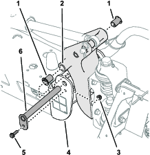
-
Remove the boom and pivot bracket assembly from the end channel of the center frame to access the nylon bushings.
-
Remove and inspect the nylon bushings from the front and back sides of the pivot bracket (Figure 108).
Note: Replace any worn or damaged bushings.
-
Lubricate the nylon bushings with a small amount of oil and install the bushings into pivot bracket (Figure 108).
-
Align the holes in the pivot bracket with the holes in the end channel (Figure 108).
-
Install the pivot pin and secure it with the flange bolt and flange locknut removed in step 3.
-
Repeat steps 2 through 8 for the other outer-boom section.
Adjusting the Booms to Level
The following procedure can be used to adjust the actuators on the center boom to keep the left and right booms at level.
-
Extend the booms to the spray position.
-
Remove the cotter pin from the pivot pin (Figure 109).
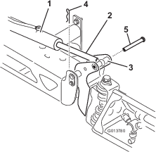
-
Lift up on the boom and remove the pin (Figure 109), and slowly lower the boom to the ground.
-
Inspect the pin for any damage, and replace it if necessary.
-
Use a wrench on the flat sides of the actuator rod to immobilize it, then loosen the jam nut to allow the eyelet rod to be adjusted (Figure 110).
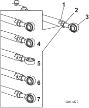
-
Turn the eyelet rod in the actuator rod to shorten or lengthen the extended actuator to the desired position (Figure 110).
Note: You must turn the eyelet rod in half or complete revolutions so that you can assemble the rod to the boom.
-
Once the desired position has been achieved, tighten the jam nut to secure the actuator and eyelet rod.
-
Raise the boom to align the pivot with the actuator rod.
-
While holding the boom, insert the pin through both boom pivot and actuator rod (Figure 109).
-
With the pin in place, release the boom and secure the pin with the cotter previously removed.
-
Repeat the procedure for each actuator rod bearing, if necessary.
Cleaning
Important: Do not use brackish or reclaimed water to clean the machine.
Cleaning the Flow meter
| Maintenance Service Interval | Maintenance Procedure |
|---|---|
| Every 200 hours |
|
-
Thoroughly rinse and drain the entire spraying system.
-
Remove the flow meter from the sprayer and flush it with clean water.
-
Remove the retainer ring on the upstream side (Figure 111).
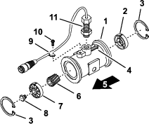
-
Clean the turbine and the turbine hub to remove metal filings and any wettable powders.
-
Inspect the turbine blades for wear.
Note: Hold the turbine in your hand and spin it. It should spin freely with little drag. If it does not, replace it.
-
Assemble the flow meter.
-
Use a low pressure (50 kPa or 5 psi) air jet to ensure that the turbine spins freely.
Note: If the turbine does not spin freely, loosen the hex stud on the bottom of the turbine hub by 1/16 of a turn until it does spins freely.
Cleaning the Sprayer Valves
-
To clean the rate control valve, refer to the following sections:
-
To clean the agitation valve; refer to the following sections:
-
To clean the master-boom valve, refer to the following sections:
-
To clean the 3 section valves; refer to the following sections:
Removing the Valve Actuator
-
Position the sprayer on a level surface, engage the parking brake, shut off the pump, shut off the engine, and remove the key.
-
Remove the 3-pin connector of the valve actuator from the 3 socket electrical connector of the sprayer harness.
-
Remove the retainer that secures the actuator to the manifold valve for the rate control, agitation, master section, or section valve (Figure 112).
Note: Squeeze the 2 legs of the retainer together while pushing it down.
Note: Retain the actuator and retainer for installation in Installing the Valve Actuator.
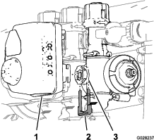
-
Remove the actuator from the manifold valve.
Removing the Rate Control Manifold Valve
-
Remove 2 flange clamps and 2 gaskets that secure the manifold for the rate control valve (Figure 113) to the pressure filter and agitation valve.
Note: Retain the flange clamps and gaskets for installation in Installing the Rate Control Manifold Valve.
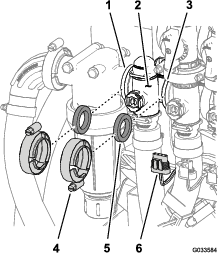
-
Remove the retainer that secure the outlet fitting to the manifold coupling for the rate control valve (Figure 114).
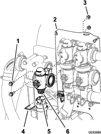
-
Remove the 2 flange-head bolts (1/4 x 3/4 inch) and 2 flange locknuts (1/4 inch) that secure the rate control valve to the valve mount and remove the valve manifold from the machine (Figure 114).
Note: If necessary, loosen the mounting hardware for the pressure filter head to ease removal of the rate control valve.
Note: Retain the flange-head bolts, flange locknuts, and retainer for installation in Installing the Agitation Manifold Valve.
Removing the Agitation Manifold Valve
-
Remove 3 flange clamps and 3 gaskets that secure the manifold for the agitation valve (Figure 115) to the agitation bypass valve, rate control valve, and master-boom valve.
Note: Retain the flange clamps and gaskets for installation in Installing the Agitation Manifold Valve.
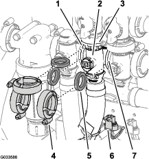
-
Remove the retainer that secure the quick-disconnect socket to the manifold quick-disconnect coupling for the agitation valve (Figure 116).
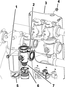
-
Remove the flange-head bolt (1/4 x 3/4 inch) and flange locknut (1/4 inch) that secure the agitation valve to the valve mount and remove the valve manifold from the machine (Figure 116).
Note: Retain the flange head bolt, flange locknut, and retainer for installation in Installing the Agitation Manifold Valve.
Removing the Master Boom Manifold Valve
-
Remove flange clamps and gaskets that secure the manifold for the master-boom valve (Figure 117) to the master-boom bypass valve, agitation valve, and 90° flanged elbow (at the end of the hose for the flow meter).
Note: Retain the flange clamps and gaskets for installation in Installing the Master Boom Manifold Valve.
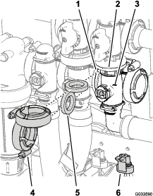
-
Remove the retainer that secure the 90° outlet fitting to the manifold coupling for the master-boom valve (Figure 118).
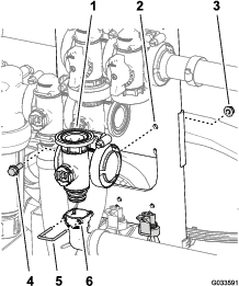
-
Remove the flange-head bolt (1/4 x 3/4 inch) and flange locknut (1/4 inch) that secure the master-boom valve to the valve mount and remove the valve manifold from the machine (Figure 118).
Note: Retain the flange-head bolt, flange locknut, and retainer for installation in Installing the Master Boom Manifold Valve.
Removing the Section Manifold Valve
-
Remove clamps and gaskets that secure the manifold for the section valve (Figure 119) to the adjacent section valve (if left section valve, and the reducer coupling).
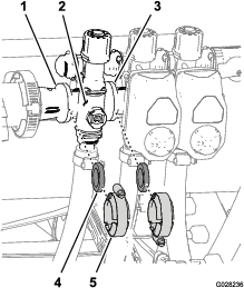
-
Remove the retainers that secure the outlet fitting to the section valve manifold and the valve manifold to the bypass fitting (Figure 120).

-
For the left or right boom section valves, remove the flanged-head bolts and flanged locknuts that secure the section valve(s) to the valve mount and remove the valve manifold(s) from the machine; for the center section valve, remove the section valve manifold from the machine (Figure 121).
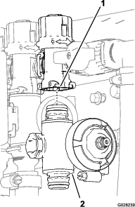
Cleaning the Manifold Valve
-
Position the valve stem so that it is in the closed position (Figure 122B).
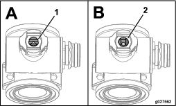
-
Remove the 2 end-cap-fitting assemblies from each end of the manifold body (Figure 123 and Figure 124).
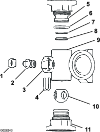
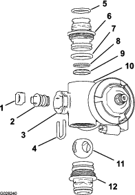
-
Turn the valve stem so that the ball is in the open position (Figure 122A).
Note: When the valve stem is parallel with the valve flow, the ball slides out.
-
Remove the stem retainer from the slots in the stem port in the manifold (Figure 123 and Figure 124).
-
Remove the stem retainer and valve stem seat from the manifold (Figure 123 and Figure 124).
-
Reach into the manifold body and remove the valve-stem assembly (Figure 123 and Figure 124).
-
Clean the inside of the manifold and exterior of the ball valve, valve-stem assembly, stem capture, and end fittings.
Assembling the Manifold Valve
Operator supplied material: Clear silicone grease.
Important: Use only silicone grease when assembling the valve.
-
Check the condition of the outlet fitting O-rings (section valve manifold only), end cap O-rings, back seating O-rings, and ball seat for damage or wear (Figure 123 and Figure 124).
Note: Replace any damaged or worn O-rings or seats.
-
Apply silicone grease to the valve stem and insert it into the valve stem seat (Figure 123 and Figure 124).
-
Install the valve stem and seat into the manifold and secure the stem and seat with the stem retainer (Figure 123 and Figure 124).
-
Ensure that the back seating O-ring and the ball seat are aligned and seated into the end-cap fitting (Figure 123 and Figure 124)
-
Install the end-cap fitting assembly onto the manifold body until the flange of the end-cap fitting touches the manifold body (Figure 123 and Figure 124), then turn the end-cap fitting an additional 1/8 to 1/4 turn.
Note: Use caution so as not to damage the end of the fitting.
-
Insert the ball into the valve body (Figure 125).
Note: The valve stem should fit inside the ball drive slot. If the valve stem does not fit, adjust the position of the ball (Figure 125).
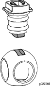
-
Turn the valve stem assembly so that the valve is closed (Figure 122B)
-
Repeat steps 4 and 5 for the other end-cap fitting assembly.
Installing the Rate Control Manifold Valve
-
Align a gasket between the flanges of the rate control valve manifold and the pressure filter head (Figure 126A).
Note: If needed, loosen the mounting hardware for the pressure filter head as needed to provide clearance.
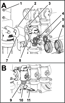
-
Assemble the rate control valve manifold, gasket, and pressure filter head with a flange clamp and tighten by hand (Figure 126A).
-
Align a gasket between the flanges of the rate control valve and the agitation-valve manifold (Figure 126A).
-
Assemble the rate control valve manifold, gasket, and agitation-valve manifold with a flange clamp and tighten by hand (Figure 126A).
-
Assemble the rate control valve to the valve mount with the 2 flanged-head bolts and 2 flanged locknuts (Figure 126A) that you removed in step 3 of Removing the Rate Control Manifold Valve, and torque the nut and bolt to 10 to 12 N∙m (90 to 110 in-lb).
-
Assemble the outlet fitting onto the coupling fitting at the bottom of the manifold for the rate control valve (Figure 126B).
-
Secure the outlet fitting coupling fitting by inserting a retainer into the socket of the outlet fitting (Figure 126B).
-
If you loosened the mounting hardware for the pressure filter head, tighten the nut and bolt to 10 to 12 N∙m (90 to 110 in-lb).
Installing the Agitation Manifold Valve
-
Align the flange of the agitation-valve manifold, a gasket, and the flange of the agitation bypass valve (Figure 127).
Note: If needed, loosen the mounting hardware for the master-boom valve as needed to provide clearance.
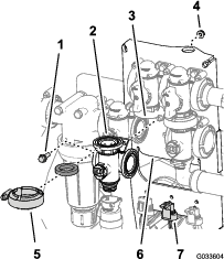
-
Assemble the agitation bypass valve, gasket, and agitation-valve manifold with a flange clamp and tighten by hand (Figure 128).
-
Align a gasket between the flanges of the rate control valve and the agitation-valve manifold (Figure 128A).
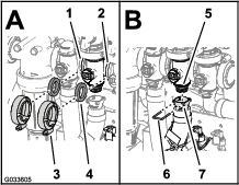
-
Assemble the rate control valve, gasket, and agitation-valve manifold with a flange clamp and tighten by hand (Figure 128A)
-
Align a gasket between the flanges of the agitation-valve manifold and the master-boom valve (Figure 128A)
-
Assemble the agitation-valve manifold, gasket, and master-boom valve with a flange clamp and tighten by hand (Figure 128A)
-
Assemble the outlet fitting onto the coupling fitting at the at the bottom of the manifold for the agitation valve (Figure 128B)
-
Secure the outlet fitting to the coupling fitting by inserting a retainer into the socket of the outlet fitting (Figure 128B)
-
Assemble the agitation valve to the valve mount with the flanged-head bolt and flanged locknut (Figure 127) that you removed in step 3 of Removing the Agitation Manifold Valve, and torque the nut and bolt to 10 to 12 N∙m (90 to 110 in-lb).
-
If you loosened the mounting hardware for the master-boom valve, tighten the nut and bolt to 10 to 12 N∙m (90 to 110 in-lb).
Installing the Master Boom Manifold Valve
-
Align the flange of the master-boom-valve manifold, a gasket, and the flange of the master-boom bypass valve (Figure 129).
-
Assemble the master-boom valve manifold, gasket, and master-boom bypass valve with a flange clamp tightened hand tight (Figure 129).
-
Align the flange of the master-boom-valve manifold, a gasket, and the agitation-valve manifold (Figure 129).
-
Assemble the master-boom-valve manifold, gasket, and agitation-valve manifold with a flange clamp and tighten by hand (Figure 129)
-
Align the socket of the 90° outlet fitting onto the coupling fitting at the at the bottom of the manifold for the master-boom valve (Figure 130).
-
Secure the outlet fitting coupling fitting by inserting a retainer into the socket of the outlet fitting (Figure 130).
-
Assemble the agitation valve to the valve mount with the flanged-head bolt and flanged locknut (Figure 129) that you removed in step 3 of Removing the Master Boom Manifold Valve, and torque the nut and bolt to 10 to 12 N∙m (90 to 110 in-lb).
Installing the Section Manifold Valve
-
Insert the upper end-cap fitting of the manifold valve into the bypass fitting (Figure 131A).
Note: If needed, loosen the mounting hardware for the bypass fitting to provide clearance.
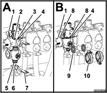
-
Secure the end-cap fitting to the bypass fitting by inserting a retainer into the socket of the bypass fitting (Figure 131A).
-
Assemble the outlet fitting onto the lower end-cap fitting of the manifold valve (Figure 131A).
-
Secure the end-cap fitting to the outlet fitting by inserting a retainer into the socket of the outlet fitting (Figure 131A).
-
Align a gasket between the flanges of the reducer coupling and the section valve manifold (Figure 131B).
-
Assemble the reducer coupling, gasket, and section valve manifold with a clamp and tighten by hand (Figure 131B).
-
If installing the 2 left most section valves, align a gasket between the flanges of the 2 adjacent section valve manifolds (Figure 131B).
-
Assemble the 2 adjacent section valve manifolds and gasket with a clamp and tighten by hand (Figure 131B).
-
For the left or right boom section valves, assemble the valves to the valve mount with the flanged-head bolt and flanged locknut that you removed in step 3 of Removing the Section Manifold Valve and torque the nuts and bolts to 10 to 12 N∙m (90 to 110 in-lb).
-
If you loosened the mounting hardware for the bypass fitting, tighten the nut and bolt to 10 to 12 N∙m (90 to 110 in-lb).
Installing the Valve Actuator
-
Align the actuator to the manifold valve and (Figure 112).
-
Secure the actuator and valve with the retainer that you removed in step 3 of Removing the Valve Actuator.
-
Connect the 3-pin connector of the valve-actuator harness to the 3-socket connector of the wire harness of the sprayer.
Storage
Storage Safety
-
Before you leave the operator’s position, do the following:
-
Park the machine on a level surface.
-
Shut off the spray pump.
-
Engage the parking brake.
-
Shut off the engine and remove the key (if equipped).
-
Wait for all movement to stop.
-
Allow the machine to cool before adjusting, servicing, cleaning, or storing it.
-
-
Do not store the machine or fuel container where there is an open flame, spark, or pilot light, such as on a water heater or other appliance.
Preparing the Machine for Storage
Short-Term Storage
(Less than 30 days)
Perform the procedures that follow:
Cleaning the Exterior of the Machine
Important: Do not use brackish or reclaimed water to clean the machine.
-
Park the machine on a level surface; engage the parking brake; shut off the spray pump and the engine; remove the key; and wait for all movement to stop before leaving the machine.
Note: For HD- and HDX-Series Workman models with a manual transmission, disengage the PTO.
-
Clean dirt and grime from the entire machine, including the outside of the cylinder-head fins of the engine and blower housing.
Important: You can wash the machine with mild detergent and water. Do not use high-pressure water to wash the machine. Pressure washing may damage the electrical system or wash away necessary grease at friction points. Avoid excessive use of water, especially near the control panel, lights, engine, and the battery.
Preparing to Condition the Sprayer
-
Move the machine to the drain pad area, engage the parking brake, shut off the spray pump, shut off the engine, remove the key, and wait for all movement to stop before leaving the operator’s position.
-
Drain the fresh-water tank and leave the tank spigot open.
-
Drain the sprayer tank as completely as possible.
-
Prepare rust inhibiting, non-alcohol based, RV antifreeze solution; refer to Preparing the Conditioner.
-
Remove 1 of the pressure-sense tubes from the push-to-connect fitting as shown in Figure 132.
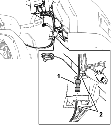
-
Start the engine and lower the outer booms sections.
Conditioning the Sprayer
-
Run the spray pump for a few minutes to circulate the RV antifreeze throughout the spray system and any installed spray accessories.
-
Turn the left, center, and right section switches to the ON position.
-
Turn the master section switch to the ON position and look for the following:
-
Ensure that RV anti-freeze flows from the disconnected end of the pressure-gauge tube.
-
Spray out the nozzle until the RV anti-freeze is visible.
-
-
Turn the master section switch to the OFF position.
-
Turn the pump switch to the OFF position.
-
Use the boom-section lift switches to raise the outer boom sections.
Raise the boom sections until they have moved completely into boom-transport cradle forming the “X” transport position and the lift cylinders are fully retracted.
Note: Make sure that the lift cylinders are fully retracted to prevent actuator rod damage.
-
Shut off the engine.
-
Drain the sprayer tank as completely as possible.
Long-Term Storage
(Longer than 30 days)
-
Clean the sprayer valves; refer to Cleaning the Sprayer Valves.
-
Grease the sprayer; refer to Lubrication.
-
Check and tighten all bolts, nuts, and screws.
Note: Repair or replace any parts that are worn or damaged.
-
Check the condition of all spray hoses.
Note: Replace any hoses that are worn or damaged.
-
Tighten all hose fittings.
-
Paint all scratched or bare metal surfaces with paint is available from your authorized Toro distributor.
-
If needed, prepare the vehicle for long-term storage; refer to the Operator’s Manual for your vehicle.
-
Store the machine in a clean, dry garage or storage area.
-
Cover the machine to protect it and keep it clean.
Preparing the Machine for Service
-
Insert the pressure-sense tube into the push-to-connect fitting until it is fully seated (Figure 133).
-
Close the spigot of the fresh-water tank.
-
Add fuel to the fuel tank.
-
Service the vehicle; refer to the Operator’s Manual for your vehicle.
Removing the Sprayer and Tank Skid
Lifting equipment capacity: 408 kg (900 lb)
Danger
The sprayer tank assembly presents a stored energy hazard. If not properly retained when installing or removing the assembly, it can move or fall and injure you or bystanders.
Use straps and an overhead lift to support the sprayer tank assembly during installation, removal, or any maintenance whenever you remove the retaining fasteners.
Preparing the Center Console
-
Disconnect the battery cables from the battery; refer to Disconnecting the Battery.
-
Separate the fuse block of the sprayer from the fuse block of the machine and disconnect the wiring between the 2 fuse blocks; refer to Installing the Sprayer Fuse Block.
-
Remove the wire harness from J-clips; refer to Routing the Rear Electrical Harness for the Sprayer to the Control Console.
-
Loosen the hand knob that is located below the console and remove the hairpin; refer to Installing the Control Console to the Machine.
-
Disconnect the terminals of the wires that connect the fuse block for the sprayer with the fuse block of the machine; refer to Installing the Sprayer Fuse Block.
-
Separate the fuse block for the sprayer from the fuse block for the machine; refer to Installing the Sprayer Fuse Block.
-
Remove the console from the console-mounting bracket at the dash of the machine and align the pivot pin on the control console with the storage bracket at the front tank strap (Figure 134); refer to Installing the Control Console to the Machine.
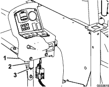
-
Assemble the console to the bracket and secure the pivot pin to the bracket with the hairpin (Figure 134).
Installing the Jack Stands
Lifting equipment capacity: 408 kg (900 lb)
-
Align the front jack stand with the jack stand receiver at the front of the tank (Figure 135).
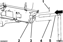
-
Insert the jack stand into the receiver until the middle hole in the horizontal jack stand tube is aligned with the hole in the top of the receiver (Figure 135).
-
Insert the clevis pin (1/2 x 3 inches) into the holes in the jack stand and receiver and secure the clevis pin with a hairpin (5/32 x 2-5/8 inches).
-
Thread a lock knob into the receiver and tighten the knob by hand (Figure 135).
-
Align the rear jack stand with the rear jack-stand receiver (Figure 136).
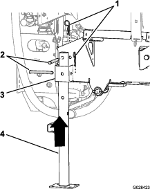
-
Align the hole in the top of the jack stand with the hole in the frame of the tank skid (Figure 136)
-
Secure the jack stand to the receiver and the frame with 2 clevis pins (1/2 x 4-1/2 inches) and 2 hairpins (5/32 x 2-5/8 inches) as shown in Figure 136.
-
Repeat steps 1 through 7 for the front and rear jack stands at the other side of the tank skid.
Removing the Sprayer Skid
-
Lower the booms to approximately 45° and then pivot them forward (Figure 137).
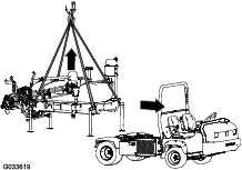
-
Remove the 2 bolts (1/2 x 1-1/2 inches) and 2 locknuts (1/2 inch) that secure the hold down bracket of the tank skid assembly to the bed bracket on the frame at each side of the machine; refer to Lowering the Tank Skid.
-
Raise the tank skid with the lift cylinders, install the cylinder lock, and perform the following:
Note: Refer to Raising the Tank Assembly.
-
For HD- and HDX-Series Workman models with a manual transmission, disconnect the PTO shaft from the transaxle PTO; refer to the installation instructions for the Multi Pro WM Turf Sprayer Finishing Kit, Manual Workman Utility Vehicle.
-
For HDX Workman with an automatic transmission, disconnect the hoses at the high-flow hydraulic panel and cap the fittings; refer to the installation instructions for the Multi Pro WM Turf Sprayer Finishing Kit, Automatic Workman Utility Vehicle.
-
Disconnect the speed sensor wiring; refer to Connecting the Speed Sensor Harness (HD-Series Models with a Manual Transmission) and Connecting the Speed Sensor Harness (HDX-Auto Model).
-
-
Remove the cylinder lock and lower the tank skid with the lift cylinders; refer to Lowering the Tank Assembly.
-
Attach the lifting equipment to the horizontal tubes of the forward jack stands and the vertical post of the rear jack stands (Figure 137).
-
Lift the tank assembly 7.5 to 10 cm (3 to 4 inches), and remove the lynch pins and clevis pins securing the lift cylinders to the tank assembly.
-
Lift the tank skid from the machine high enough to clear the skid from the machine (Figure 137).
-
Carefully move the vehicle forward and away from the tank skid.
-
Slowly lower the skid tank to the ground.
Troubleshooting
| Problem | Possible Cause | Corrective Action |
|---|---|---|
| A section does not spray. |
|
|
| A section does not turn off. |
|
|
| A section valve is leaking. |
|
|
| The spray nozzle(s) drip when the section switch(es) is shut off |
|
|
| A pressure drop occurs when you turn on a boom. |
|
|
Schematics
Flow Diagram, Sprayer System