| Maintenance Service Interval | Maintenance Procedure |
|---|---|
| Before each use or daily |
|
Introduction
This machine is a dedicated turf spray application vehicle and is intended to be used by professional, hired operators in commercial applications. It is designed primarily for spraying on well-maintained lawns in parks, golf courses, sports fields, and on commercial grounds.
This machine is designed primarily for off-road use and is not intended for extensive driving on public roads. Using this product for purposes other than its intended use could prove dangerous to you and bystanders.
Read this information carefully to learn how to operate and maintain your product properly and to avoid injury and product damage. You are responsible for operating the product properly and safely.
Visit www.Toro.com for more information, including safety tips, training materials, accessory information, help finding a dealer, or to register your product.
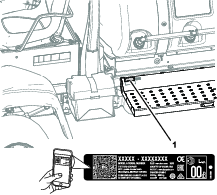
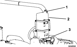
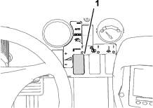
Whenever you need service, genuine Toro parts, or additional information, contact an Authorized Service Dealer or Toro Customer Service and have the model and serial numbers of your product ready. Figure 1 identifies the location of the model and serial numbers on the product. Write the numbers in the space provided.
Important: With your mobile device, you can scan the QR code on the serial number decal (if equipped) to access warranty, parts, and other product information.
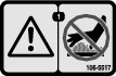
This manual identifies potential hazards and has safety messages identified by the safety-alert symbol (Figure 2), which signals a hazard that may cause serious injury or death if you do not follow the recommended precautions.

This manual uses 2 words to highlight information. Important calls attention to special mechanical information and Note emphasizes general information worthy of special attention.
This product complies with all relevant European directives; for details, please see the separate product specific Declaration of Conformity (DOC) sheet.
It is a violation of California Public Resource Code Section 4442 or 4443 to use or operate the engine on any forest-covered, brush-covered, or grass-covered land unless the engine is equipped with a spark arrester, as defined in Section 4442, maintained in effective working order or the engine is constructed, equipped, and maintained for the prevention of fire.
The enclosed engine owner's manual is supplied for information regarding the US Environmental Protection Agency (EPA) and the California Emission Control Regulation of emission systems, maintenance, and warranty. Replacements may be ordered through the engine manufacturer.
Warning
CALIFORNIA
Proposition 65 Warning
The engine exhaust from this product contains chemicals known to the State of California to cause cancer, birth defects, or other reproductive harm.
Battery posts, terminals, and related accessories contain lead and lead compounds, chemicals known to the State of California to cause cancer and reproductive harm. Wash hands after handling.
Use of this product may cause exposure to chemicals known to the State of California to cause cancer, birth defects, or other reproductive harm.
Safety
This machine has been designed in accordance with EN-ISO 4254-1 and 4254-6, and SAE J2258.
General Safety
This product is capable of causing personal injury. Always follow all safety instructions to avoid serious personal injury.
-
Read and understand the contents of this Operator’s Manual before starting the engine.
-
Use your full attention while operating the machine. Do not engage in any activity that causes distractions; otherwise, injury or property damage may occur.
-
Use appropriate personal protective equipment (PPE) to guard against contact with chemicals. Chemical substances used in the sprayer system may be hazardous and toxic.
-
Do not put your hands or feet near moving components of the machine.
-
Do not operate the machine without all guards and other safety protective devices in place and working on the machine.
-
Keep clear of any discharge area of the sprayer nozzles and spray drift. Keep bystanders and children out of the operating area.
-
Never allow children to operate the machine.
-
Park the machine on a level surface, engage the parking brake, shut off the engine, remove the key (if equipped), and wait for all movement to stop before you leave the operator’s position. Allow the machine to cool before adjusting, servicing, cleaning, or storing it.
Improperly using or maintaining this machine can result in injury.
To reduce the potential for injury, comply with these safety instructions
and always pay attention to the safety-alert symbol  , which means Caution, Warning,
or Danger—personal safety instruction. Failure to comply with
these instructions may result in personal injury or death.
, which means Caution, Warning,
or Danger—personal safety instruction. Failure to comply with
these instructions may result in personal injury or death.
Not all the attachments that adapt to this machine are covered in this manual. Refer to the operator’s manual provided with each attachment for additional safety instructions.
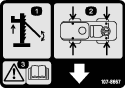
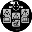
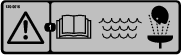
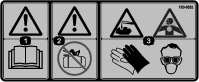
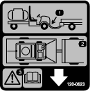
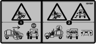
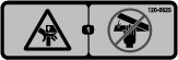
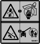
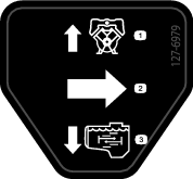
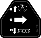
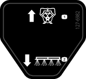
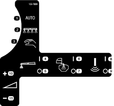
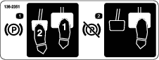
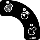
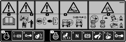
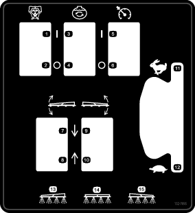
Safety and Instructional Decals
 |
Safety decals and instructions are easily visible to the operator and are located near any area of potential danger. Replace any decal that is damaged or missing. |


Setup
Note: Determine the left and right sides of the machine from the normal operating position.
Note: If you have questions or need additional information regarding the spray control system, refer to the Operator’s Manual supplied with the system.
Important: This sprayer is sold without spray nozzles.To use the sprayer, you must obtain and install the nozzles. Contact your authorized Toro distributor for information on the available section kit and accessories. After you install your nozzles and before using the sprayer for the first time, adjust the section bypass valves so that the pressure and application rate remains the same for all sections when you turn 1 or more sections off. Refer to Adjusting the Section Bypass Valves.
Assembling the Sprayer Tank Fill Fitting
Parts needed for this procedure:
| Quick-disconnect fitting | 1 |
Note: To complete this procedure, you will need to supply a hose with 1 inch male national pipe thread (NPT) fitting and PTFE thread sealant.
-
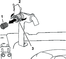
At the forward, right side of the tank cover, remove the 2 hairpins that secure the latches for the quick-disconnect coupling for the anti-siphon fill receptacle (Figure 3).
-
Rotate the latches open to unlock the quick-disconnect fitting from the quick-disconnect coupling (Figure 3).
-
Remove the quick-disconnect fitting from the quick-disconnect coupling (Figure 3).
-
Close the latches and install the hair pins into the flanges of the quick-disconnect coupling (Figure 3).
-
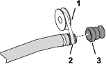
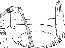
Apply PTFE thread sealant (Figure 4) to the threads of the fill hose fitting (1 inch—national pipe thread).
-
Thread the quick-disconnect coupling onto the fill hose and tighten it by hand (Figure 4).
Checking the Outer Boom Cradles
-
Engage the parking brake, start the engine, and set the throttle to idle.
-
Slowly raise the left or right outer boom until it first contacts the upper cradle tube.
-
Slowly raise the other outer boom until it first contacts the cradle.
-
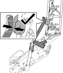
Look at the area on the upper cradle tubes where the slide blocks on the top tube of the outer boom contact the cradles.
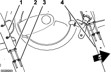
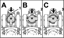
Note: The cradle is adjusted correctly when the blocks contact the cradle at the bend in the upper cradle tube (Figure 5).
-
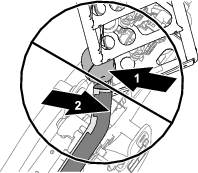
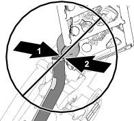
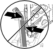
If either upper cradle tube is misaligned with the slide block as shown in Figure 6, Figure 7, or Figure 8, adjust the cradle position; refer to Aligning the Cradles to the Outer Booms.
-
Lower both outer booms, shut off the engine, remove the key, and wait for moving parts to stop.
Removing the Shipping Bumper
Installing the CE Kit
Machines Operated in EU Countries
Install the CE kit for your machine; refer to the Multi Pro 5800 CE Kit Installation Instructions.
Product Overview
Vehicle Controls
Traction Pedal
The traction pedal (Figure 13) controls the movement of the machine, both forward and reverse. Using the toe or heel of your right foot, press the top of the pedal to move forward or the bottom of the pedal to move the machine in reverse. Release the pedal to slow and stop the machine.
Important: Ensure that you allow the sprayer to come to a stop before switching between the FORWARD and the REVERSE positions.
Note: The farther you press the pedal in either direction, the faster the sprayer travels. To obtain maximum forward speed, set the throttle lever to the FAST position and press the traction pedal all the way forward.
Note: To get maximum power under heavy load or when ascending a hill, move the throttle in the FAST position while pressing traction pedal slightly to keep the engine speed high. When the engine speed begins to decrease, release the traction pedal slightly to allow the engine speed to increase.
Brake Pedal
Use the brake pedal to stop or slow the machine (Figure 13).
Caution
If you operate the sprayer with poorly adjusted or worn brakes, you could lose control of the sprayer, resulting in serious injury or death to you or bystanders.
Always check the brakes before operating the sprayer and keep them properly adjusted and repaired.
Parking Brake
The parking brake is a pedal to the left of the brake pedal (Figure 13). Engage the parking brake whenever you leave the seat to prevent the sprayer from accidently moving. To engage the parking brake, press the brake pedal and while holding the brake, press the parking-brake pedal. To disengage, press and release the brake pedal. If the sprayer is parked on a steep grade, apply the parking brake and place chocks on the downhill side of the wheels.
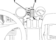
Ignition Switch
The ignition switch (Figure 12), is used to start and shut off the engine, and the switch has 3 positions: OFF, ON/PREHEAT, and START.
Speed-Lock Switch
The speed-lock switch locks the position of the traction pedal when the switch is set (Figure 14). This ensures that the sprayer travels at a constant speed while driving the machine on level ground.

Throttle Lever
The throttle lever is located on the control panel between the seats (Figure 14), and the throttle is used to control the engine speed. Push the lever forward to increase the engine speed and pull it rearward to decrease the engine speed.
Work-Light Switch
Toggle the switch to operate the work lights (Figure 12). Push it forward to turn the lights on and rearward to turn them off.
Fuel Gauge
The fuel gauge is located on the dash of the machine and the gauge displays the level of the fuel in the tank (Figure 12).
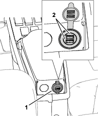
USB Power Port
The 2-socket USB power port is located at the back of the armrest (Figure 15).
Sprayer Controls
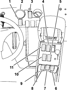
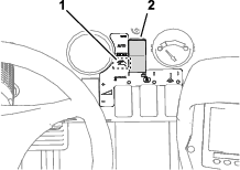
Pressure Gauge
The pressure gauge (Figure 16) is located on the dash. This gauge shows the pressure of the fluid in the spray system in psi and kPa.
Spray-Mode Switch
Use the spray-mode switch to change between the application rate mode (closed loop) and the manual mode (open loop).
Application-Rate Switch
The application-rate switch is located on the dash to the right of the steering wheel (Figure 16). Use the application-rate switch to control the spray pump speed when operating the sprayer in the manual mode. Press and hold the switch forward to increase the application rate (pressure), or press and hold it rearward to decrease the application rate (pressure).
Spray-Pump Switch
The spray-pump switch is located on the center console to the right of the seat (Figure 16). Toggle this switch forward to run the spray pump or rearward to stop the pump. When the switch is turned on, a light on the switch illuminates.
Important: Engage the spray-pump switch only when the engine is at LOW IDLE to avoid damaging the pump drive.
Boom-Section Lift Switches
The boom-section lift switches are located on the center console to the right of the seat and used to raise or lower the left and right boom sections (Figure 16).
Master Section Switch
The master section switch is located on the center console of the machine. The switch allows you to start or stop the spray operation. Press the switch to enable or disable the spray system (Figure 16).
Left, Center, and Right Section Switches
The 3 section switches are located on the center console in the front of the armrest (Figure 16). Toggle each switch forward to turn the corresponding section on and rearward to turn each off. When the switch is in the ON position, an icon appears at the top of the InfoCenter.
Note: These switches affect the spray system only when the master section switch is in the ON position.
Agitation Switch
The agitation switch is located on the center console to the right of the seat (Figure 16). Toggle this switch forward to turn on the agitation in the tank or rearward to stop the agitation. When the switch is turned on, a light on the switch illuminates. To operate the agitation function, you must run the sprayer system pump and you must run the engine above low idle.
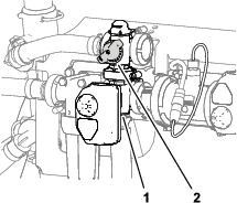
Agitation-Bypass Valve
The agitation-bypass valve redirects the flow of fluid to the sprayer-system pump when you turn off the agitation function (Figure 17). The agitation-bypass valve is located above the agitation valve. You can adjust the bypass valve to ensure that the pressure remains constant when cycling agitation on or off; refer to Calibrating the Agitation-Bypass Valve.
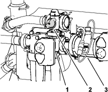
Flowmeter
The flowmeter measures the flow rate of the fluid for use by the InfoCenter system and when spraying in the application rate mode (Figure 17).
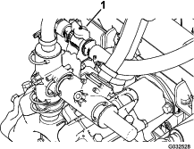
Agitation-Throttle Valve
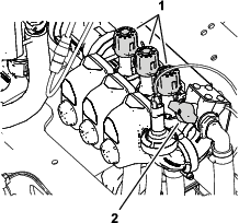
The agitation-throttle valve is a manually-operated ball valve that controls flow to the agitation nozzles in the main tank. This valve allows you to control the sprayer-system pressure at the agitation nozzles of the main tank when larger application rates are required. The agitation-throttle valve is located above the pump (Figure 18).
Section Bypass Valves
The section bypass valves are used to adjust the sprayer system pressure to the section valves to ensure that the sprayer pressure to the spray section remains constant no matter how many spray sections are on (Figure 19).
Note: Use the bypass valves when spraying in the manual mode (open loop) only.
Section-Bypass Shutoff Valve
Use the section-bypass shutoff valve to control fluid flow from the section bypass valves to the tank when spraying in the manual mode (open loop); refer to Figure 19.
Note: Close the section-bypass shut off valve when spraying in the application rate mode (closed loop).
Anti-Siphon Fill Receptacle
At the front of the tank cover is a hose receptacle with a threaded fitting, a 90-degree barbed fitting, and a short hose, which you can direct toward the tank opening. This receptacle allows you to connect a water hose to it and fill the tank with water without contaminating the hose with the chemicals in the tank.
Important: Do not lengthen the hose to allow contact with the tank fluids. The distance from the end of the hose to the uppermost water level should be within local regulatory limits.
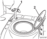
Tank Cover
The tank cover is located in the center, top of the tank. To open the cover, shut off the engine, turn the front half of the cover to the left, and swing it open. You can remove the strainer inside for cleaning. To seal the tank, close the cover and rotate the front half toward the right.
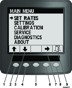
InfoCenter Controls
The InfoCenter controls use the 5 buttons below the LED display to navigate menus, enter data, and change functions.
Note: Specifications and design are subject to change without notice.
| Description | Measurement |
|---|---|
| Base weight | 1307 kg (2,882 lb) |
| Weight with standard spray system, empty, without operator | 1307 kg (2,882 lb) |
| Weight with standard spray system, full, without operator | 2499 kg (5,510 lb) |
| Maximum gross vehicle weight (GVW) (on level ground) | 3023 kg (6,665 lb) |
| Tank capacity | 1135.6 L (300 US gallons) |
| Overall width with standard spray system sections stored in the X position | 226 cm (89 inches) |
| Description | Measurement |
|---|---|
| Overall length with standard spray system | 391 cm (154 inches) |
| Overall length with standard spray system to the top of the sections stored in the X position | 442 cm (174 inches) |
| Overall height with standard spray system | 146 cm (57.5 inches) |
| Overall height with standard spray system to the top of the sections stored in the X position | 231 cm (91 inches) |
| Ground clearance | 18.4 cm (7.25 inches) |
| Wheel base | 198 cm (78 inches) |
Attachments/Accessories
A selection of Toro approved attachments and accessories is available for use with the machine to enhance and expand its capabilities. Contact your authorized Toro distributor.
To ensure optimum performance and continued safety certification of the machine, use only genuine Toro replacement parts and accessories. Replacement parts and accessories made by other manufacturers could be dangerous, and such use could void the product warranty.
Operation
Note: Determine the left and right sides of the machine from the normal operating position.
Before Operation
Before Operation Safety
General Safety
-
Never allow children or untrained people to operate or service the machine. Local regulations may restrict the age of the operator. The owner is responsible for training all operators and mechanics.
-
Become familiar with the safe operation of the equipment, operator controls, and safety signs.
-
Shut off the engine, remove the key (if equipped), and wait for all movement to stop before you leave the operator’s position, Allow the machine to cool before adjusting, servicing, cleaning, or storing it.
-
Know how to stop the machine and shut off the engine quickly.
-
Check that operator-presence controls, safety switches, and guards are attached and functioning properly. Do not operate the machine unless they are functioning properly.
-
If the machine does not function correctly or is damaged in any way, do not use the machine. Correct the problem before you operate the machine or attachment.
-
Ensure that the operator and passenger areas are clean and free from chemical residue and debris buildup.
-
Ensure that all fluid line connectors are tight and that all hoses are in good condition before applying pressure to the system.
Fuel Safety
-
Use extreme care in handling fuel. It is flammable and its vapors are explosive.
-
Extinguish all cigarettes, cigars, pipes, and other sources of ignition.
-
Use only an approved fuel container.
-
Do not remove the fuel cap or fill the fuel tank while the engine is running or hot.
-
Do not add or drain fuel in an enclosed space.
-
Do not store the machine or fuel container where there is an open flame, spark, or pilot light, such as on a water heater or other appliance.
-
If you spill fuel, do not attempt to start the engine; avoid creating any source of ignition until the fuel vapors have dissipated.
Chemical Safety
Chemical substances used in the sprayer system may be hazardous and toxic to you, bystanders, and animals, and they may damage plants, soil, and other property.
-
Read the information on each chemical. Refuse to operate or work on the sprayer if this information is not available.
-
Before working on a sprayer system, ensure that it has been neutralized and triple rinsed according to the recommendations of the chemical manufacturer(s) and that all the valves have been cycled 3 times.
-
Verify that there is an adequate supply of clean water and soap nearby, and immediately wash off any chemicals that contact you.
-
Carefully read and follow the chemical warning labels and safety data sheets (SDSs) for all chemicals used, and protect yourself according to the chemical manufacturer's recommendations.
-
Always protect your body while using chemicals. Use the appropriate personal protective equipment (PPE) to guard against contact with chemicals, such as the following:
-
safety glasses, goggles, and/or face shield
-
a chemical suit
-
a respirator or filter mask
-
chemical-resistant gloves
-
rubber boots or other substantial footwear
-
a clean change of clothes, soap, and disposable towels for cleanup
-
-
Obtain proper training before using or handling chemicals.
-
Use the correct chemical for the job.
-
Follow the chemical manufacturer's instructions for the safely applying the chemical. Do not exceed the recommended system application pressure.
-
Do not fill, calibrate, or clean the machine while people, especially children, or pets are in the area.
-
Handle chemicals in a well-ventilated area.
-
Do not eat, drink, or smoke while working near chemicals.
-
Do not clean spray nozzles by blowing through them or placing them in your mouth.
-
Always wash your hands and other exposed areas as soon as possible after working with chemicals.
-
Keep chemicals in their original packages and stored in a safe location.
-
Properly dispose of unused chemicals and chemical containers as instructed by the chemical manufacturer and your local codes.
-
Chemicals and fumes are dangerous; never enter the tank or place your head over or in the opening of a tank.
-
Follow all local, state, and federal regulations for spreading or spraying chemicals.
Performing Pre-Starting Checks
Check the following items each time you begin use of the sprayer for the day:
-
Check the air pressure in the tires.
Note: The tires of this machine are different than car tires; they require less air pressure to minimize turf compaction and damage.
-
Check all fluid levels and add the appropriate amount of specified fluids, if any are found to be low.
-
Check the brake pedal operation.
-
Check to see that the lights are working.
-
Turn the steering wheel to the left and right to check steering response.
-
With the engine shut off, check for oil leaks, loose parts, and any other noticeable malfunctions.
If any of the above items are not correct, notify your mechanic or check with your supervisor before taking the sprayer out for the day. Your supervisor may want you to check other items daily, so ask what inspections you are responsible to perform.
Preparing the Machine
Checking the Engine-Oil Level
Before you start the engine and use the machine, check the oil level in the engine crankcase; refer to Checking the Engine Oil.
Checking the Cooling System
Before you start the engine and use the machine, check the cooling system; refer to Checking the Coolant Level.
Checking the Hydraulic System
Before you start the engine and use the machine, check the hydraulic system; refer to Checking the Hydraulic Fluid.
Checking the Tire Air Pressure
| Maintenance Service Interval | Maintenance Procedure |
|---|---|
| Before each use or daily |
|
Check the tire air pressure in the tires to ensure proper levels. Fill the tires to 138 kPa (20 psi).
Note: Also, check the tires for wear or damage.
Checking the Brakes
| Maintenance Service Interval | Maintenance Procedure |
|---|---|
| Before each use or daily |
|
Before starting the sprayer, lightly press the brake pedal. If the pedal travels more than 2.5 cm (1 inch) before you feel resistance, adjust the brakes; refer to Adjusting the Brakes.
Warning
If you operate the sprayer with poorly adjusted or worn brakes, you could lose control of the sprayer, resulting in serious injury or death to you or bystanders.
Always check the brakes before operating the sprayer and keep them properly adjusted and repaired.
Adding Fuel
Fuel Specification
| Petroleum fuel | Use unleaded gasoline with an octane rating of 87 or higher ((R+M)/2 rating method). |
| Ethanol blended fuel | Use an unleaded-gasoline blend with up to 10% ethanol (gasohol) or 15% MTBE (methyl tertiary butyl ether) by volume is acceptable. Ethanol and MTBE are not the same. |
| Gasoline with 15% ethanol (E15) by volume is not approved for use. Never use gasoline that contains more than 10% ethanol by volume, such as E15 (contains 15% ethanol), E20 (contains 20% ethanol), or E85 (contains up to 85% ethanol). Using unapproved gasoline may cause performance problems and/or engine damage which may not be covered under warranty. |
Important: For best results, use only clean, fresh fuel (less than 30 days old).
-
Do not use gasoline containing methanol.
-
Do not store fuel either in the fuel tank or fuel containers over the winter unless you use a fuel stabilizer.
-
Do not add oil to gasoline.
Filling the Fuel Tank
Fuel tank capacity: approximately 45 L (12 US gallons).
-
Park the machine on a level surface, engage the parking brake, shut off the spray pump, shut off the engine, remove the key, and allow the engine to cool.
-
Clean the area around the fuel-tank cap (Figure 22).
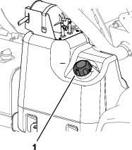
-
Remove the fuel-tank cap.
-
Fill the tank to about 2.5 cm (1 inch) below the top of the tank (bottom of the filler neck).
Note: This air space in the tank allows fuel to expand. Do not overfill the tank.
-
Install the fuel-tank cap to the tank securely.
-
Wipe up any fuel that may have spilled.
Breaking in a New Machine
| Maintenance Service Interval | Maintenance Procedure |
|---|---|
| After the first 100 hours |
|
-
Check the engine-oil and fluid levels regularly and be alert for indications of overheating in any component of the sprayer.
-
After starting a cold engine, let it warm up for about 15 seconds before accelerating.
-
Avoid racing the engine.
-
Vary the sprayer speed during operation. Avoid fast starts and quick stops.
-
Refer to for any special, low-hour checks.
Preparing the Sprayer
Selecting a Nozzle
Note: Refer to the nozzle-selection guide that is available through your authorized Toro distributor.
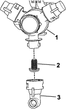
The turret bodies can accept up to 3 different nozzles. To select the desired nozzle, perform the following:
-
Stop the sprayer on a level surface, shut off the engine, remove the key, and engage the parking brake.
-
Set the master section switch to the OFF position and set the spray-pump switch to the OFF position.
-
Rotate the turret of the nozzles in either direction to the correct nozzle.
-
For machines operated in the application rate mode, perform a flow calibration; refer to the Software Guide for the Multi Pro 5800-D and 5800-G turf sprayers with ExcelaRate spray system.
Selecting a Suction Filter
Standard Equipment: 50 mesh suction filter (blue)
Use the suction filter table to identify the screen mesh for the spray nozzles you are using based on chemicals products or solutions with a viscosity equivalent to water.
| Spray Nozzle Color Code (flow rate) | Screen Mesh Size* | Filter Color Code |
|---|---|---|
| Yellow (0.2 gpm) | 50 | Blue |
| Red (0.4 gpm) | 50 | Blue |
| Brown (0.5 gpm) | 50 (or 30) | Blue (or green) |
| Gray (0.6 gpm) | 30 | Green |
| White (0.8 gpm) | 30 | Green |
| Blue (1.0 gpm) | 30 | Green |
| Green (1.5 gpm) | 30 | Green |
| *The mesh size of the suction filters in this table are based on spray chemicals or solutions with the viscosity equivalent to water. | ||
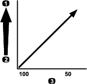
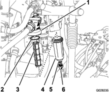
Important: When you spray with higher viscosity (thicker) chemical products or solutions with wettable powders, you may need to use a coarser screen mesh for the optional suction filter; refer to Figure 23.
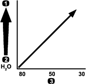
When you spray at a higher application rate, consider using a coarser optional suction-filter mesh; refer to Figure 24.

Selecting a Pressure Filter
Available screen sizes include:
Standard Equipment: 50 mesh suction filter (blue)
Use the pressure filter table to identify the screen mesh for the spray nozzles you are using based on chemicals products or solutions with a viscosity equivalent to water.
| Spray Nozzle Color Code (flow rate) | Screen Mesh Size* | Filter Color Code |
|---|---|---|
| As required for low viscosity chemicals or solutions or low application rates | 100 | Green |
| Yellow (0.2 gpm) | 80 | Yellow |
| Red (0.4 gpm) | 50 | Blue |
| Brown (0.5 gpm) | 50 | Blue |
| Gray (0.6 gpm) | 50 | Blue |
| White (0.8 gpm) | 50 | Blue |
| Blue (1.0 gpm) | 50 | Blue |
| Green (1.5 gpm) | 50 | Blue |
| As required for high viscosity chemicals or solutions or high application rates | 30 | Red |
| As required for high viscosity chemicals or solutions or high application rates | 16 | Brown |
| *The mesh size of the pressure filters in this table are based on spray chemicals or solutions with the viscosity equivalent to water. | ||
Important: When you spray with higher viscosity (thicker) chemical products or solutions with wettable powders, you may need to use a coarser screen mesh for the optional pressure-filter; refer to Figure 25.
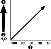
When you spray at a higher application rate, consider using a coarser optional pressure-filter mesh; refer to Figure 26.
Selecting a Nozzle-Tip Filter (Optional)
Note: The use the optional nozzle-tip filter to protect the spray-nozzle tip and increase its service life.
Use the nozzle-tip filter table to identify the screen mesh for the spray nozzles you are using based on chemicals products or solutions with a viscosity equivalent to water.
| Spray Nozzle Color Code (flow rate) | Filter Mesh Size* | Filter Color Code |
|---|---|---|
| Yellow (0.2 gpm) | 100 | Green |
| Red (0.4 gpm) | 50 | Blue |
| Brown (0.5 gpm) | 50 | Blue |
| Gray (0.6 gpm) | 50 | Blue |
| White (0.8 gpm) | 50 | Blue |
| Blue (1.0 gpm) | 50 | Blue |
| Green (1.5 gpm) | 50 | Blue |
| *The mesh size of the nozzle filters in this table are based on spray chemicals or solutions with the viscosity equivalent to water. | ||
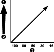
Important: When you spray with higher viscosity (thicker) chemical products or solutions with wettable powders, you may need to use a coarser screen mesh for the optional tip-filter; refer to Figure 27.
When you spray at a higher application rate, consider using a coarser tip-filter mesh; refer to Figure 28.
Filling the Tanks
Filling the Fresh-Water Tank
Important: Do not use reclaimed water (gray water) in the fresh-water tank.
Note: The fresh-water tank is used to supply a source of fresh water for you to wash chemicals off your skin, eyes, or other surfaces in the case of accidental exposure.
Always fill the fresh-water tank with clean water before handling or mixing any chemicals.
-
To fill the tank, unscrew the cap at the top of the tank, fill the tank with fresh water, and install the cap (Figure 29).
-
To open the fresh-water tank spigot, turn the lever on the spigot (Figure 29).
Filling the Spray Tank
Install the optional Chemical Pre-Mix Kit for optimal mixing and exterior tank cleanliness.
Important: Whenever possible, do not use reclaimed water (gray water) in the spray tank.
Important: Ensure that the chemicals you use are compatible with Viton™ (see the manufacturer's label; it should indicate if it is not compatible). Using a chemical that is not compatible with Viton will degrade the O-rings in the sprayer, causing leaks.
Important: The tank-volume markings are for reference only and cannot be considered accurate for calibration.
-
Stop the machine on a level surface, shut off the engine, remove the key, and engage the parking brake.
-
Determine the amount of water needed to mix the amount of chemical you need as prescribed by the chemical manufacturer.
-
Open the tank cover on the spray tank.
Note: The tank cover is located at the center of the top of the tank. To open it, turn the front half of the cover counterclockwise and swing it open. You can remove the strainer under the tank cover and clean the strainer.
-
Assemble the fill hose to the quick disconnect fitting of the anti-siphon fill receptacle.
-
Add 3/4 of the required water to the spray tank (Figure 30).
Important: Always use fresh, clean water in the spray tank. Do not pour concentrate into an empty tank.
-
Start the engine, engage the parking brake, set the spray-pump switch to the ON position, and move the throttle lever to HIGH IDLE.
-
Set the agitation switch to the ON position.
Important: Prior to introducing wettable powders into any Toro Spray System mix the powders in a suitable container with enough fresh water to create a free flowing slurry. Failure to do so may result in chemical deposits on the bottom of the tank, degraded agitation, clogging of filters, and improper application rates.Toro recommends using the approved Eductor Kit for this machine. Contact your authorized Toro distributor for more information.
-
Add the proper amount of chemical concentrate to the tank, as directed by the chemical manufacturer.
-
Add the remaining water to the tank, remove the fill hose, and close the tank cover.
Note: To seal the tank, close the cover and rotate the front half clockwise.
Important: After filling the tank for the first time, check the tank straps for any play. Tighten as necessary.
Inspecting the Tank Straps
| Maintenance Service Interval | Maintenance Procedure |
|---|---|
| Before each use or daily |
|
Important: Overtightening the tank strap fasteners can result in deforming and damaging the tank and straps.
Important: Whenever possible, do not use reclaimed water (gray water) in the spray tank.
-
Fill the main tank with water.
-
Check to see if there is any movement between the tank straps and the tank (Figure 31).
-
If the tank straps fit loose to the tank, tighten the flanged locknuts and bolts at the top of straps until the straps are flush with the surface of the tank (Figure 31).
Note: Do not overtighten the tank strap hardware.
Calibrating the Section-Bypass Valves
Manual Mode Only
Important: When operating in application rate mode, you must set the section-bypass valves to the closed position.
Important: Whenever possible, do not use reclaimed water (gray water) in the spray tank.
Before using the sprayer for the first time, whenever you change the nozzles, or as needed, calibrate the sprayer flow, speed, and set the section bypass.
Important: Select an open flat area to perform this procedure.
Preparing the Machine
-
Fill the spray tank halfway with clean water.
-
Lower the spray sections.
-
Engage the parking brake.
-
Set the spray control switch to manual.
-
Set the 3 section switches to the ON position, but leave the master section switch in the OFF position.
-
Set the spray-pump switch to the ON position, and turn on the agitation.
-
On the InfoCenter, navigate to the Calibration screen and select Test Speed; refer to Simulating a Test Speed in the Software Guide for the Multi Pro 5800-D and 5800-G turf sprayer with ExcelaRate spray system.
-
Press buttons 3 or 4 to raise or lower the simulated speed to 5.6 km/h (3.5 mph).
-
Press button 4 to toggle ON test speed simulation.
-
Press button 5 to save and exit the TEST SPEED screen.
-
Adjusting the Section Bypass Valves
-
Using the application-rate switch, adjust the application rate according to the table that follows.
Nozzle Application Rate Table
Nozzle Color SI (Metric) English Turf Yellow 159 L/ha 17 gpa 0.39 gpk Red 319 L/ha 34 gpa 0.78 gpk Brown 394 L/ha 42 gpa 0.96 gpk Gray 478 L/ha 51 gpa 1.17 gpk White 637 L/ha 68 gpa 1.56 gpk Blue 796 L/ha 85 gpa 1.95 gpk Green 1,190 L/ha 127 gpa 2.91 gpk -
Turn off the left-section switch and adjust the section-bypass knob (Figure 32) until the rate displayed is at the previous level according to the table.
Note: The numbered indicators on the bypass knob and needle are for reference only.
-
Turn on the left-section switch and turn off the right-section switch.
-
Adjust the right section-bypass knob (Figure 32) until the rate displayed is at the previous level according to the table.
-
Turn on the right-section switch and turn off the center-section switch.
-
Adjust the center section-bypass knob (Figure 32) until the rate displayed is at the previous level according to the table.
-
Turn off the master section switch.
-
Turn off the spray pump.
Agitation-Bypass Valve Knob Position
-
The agitation-bypass valve is in the full-open position as shown in Figure 33A.
-
The agitation-bypass valve is in the closed (0) position as shown in Figure 33B.
-
The agitation-bypass valve is in an intermediate (adjusted relative to the pressure gauge for the sprayer system) position as shown in Figure 33C.
Calibrating the Agitation-Bypass Valve
| Maintenance Service Interval | Maintenance Procedure |
|---|---|
| Yearly |
|
Important: Whenever possible, do not use reclaimed water (gray water) in the spray tank.
-
Select an open, flat area to perform this procedure.
-
Fill the spray tank half full with clean water.
-
Verify that the agitation-control valve is open.
Note: If it has been adjusted, open it completely at this time.
-
Engage the parking brake and start the engine.
-
Set the sprayer mode button to the Manual Mode; refer to Spraying in the Manual Mode.
-
Set the spray-pump switch and the agitation switch to the ON position.
-
Turn the master section switch to the OFF position.
-
Move the throttle lever to the FAST position.
-
Use the application-rate switch to adjust the sprayer-system pressure to 689 kPa (100 psi).
-
Turn the agitation switch to the OFF position and read the pressure gauge.
-
If the pressure gauge indicates 689 kPa (100 psi), the agitation-bypass valve is properly calibrated.
-
If the pressure gauge indicates differently, continue to the next step.
-
-
Adjust the agitation-bypass valve (Figure 34) on the backside of the agitation valve until the sprayer system pressure indicated on the gauge indicates 689 kPa (100 psi).
-
Turn the spray-pump switch to the OFF position.
-
Move the throttle lever to the IDLE/SLOW position and turn the key switch to the OFF position.
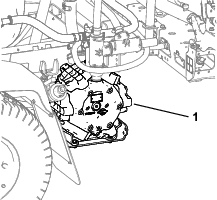
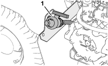
Locating the Spray Pump
The spray pump is located near the back of the tank on the left side (Figure 35).
During Operation
During Operation Safety
General Safety
-
The owner/operator can prevent and is responsible for accidents that may cause personal injury or property damage.
-
Wear appropriate clothing, including eye protection; long pants; substantial, slip-resistant footwear; and hearing protection. Tie back long hair and do not wear loose clothing or loose jewelry.
-
Wear appropriate personal protective equipment as directed in Chemical Safety.
-
Use your full attention while operating the machine. Do not engage in any activity that causes distractions; otherwise, injury or property damage may occur.
-
Do not operate the machine while ill, tired, or under the influence of alcohol or drugs.
-
Do not carry more than 1 passenger on the machine; the passenger should sit in the designated seating position only.
-
Operate the machine only in good visibility. Avoid holes or hidden hazards.
-
Before you start the engine, ensure that you are in the operating position, the traction pedal is in the NEUTRAL position, and the parking brake is engaged.
-
Remain seated whenever the machine is in motion. Keep both hands on the steering wheel whenever possible, and always keep your arms and legs within the operator’s compartment.
-
Use care when approaching blind corners, shrubs, trees, or other objects that may obscure your vision.
-
Before backing up, look rearward and ensure that no one is behind you. Back up slowly.
-
Never spray while people, especially children, or pets are nearby.
-
Do not operate the machine near drop-offs, ditches, or embankments. The machine could suddenly roll over if a wheel goes over the edge or if the edge gives way.
-
Reduce the speed when operating on rough terrain, uneven ground, and near curbs, holes, and other sudden changes in terrain. Loads may shift, causing the machine to become unstable.
-
Stop the machine, shut off the engine, remove the key, engage the parking brake, and inspect for damage after striking an object or if there is an abnormal vibration in the machine. Make all necessary repairs before resuming operation.
-
Slow down and use caution when making turns and crossing roads and sidewalks with the machine. Always yield the right-of-way.
-
Use extra caution when operating the machine on wet surfaces, in adverse weather conditions, at higher speeds, or with a full load. Stopping time and distance increase in these conditions.
-
Do not touch the engine or muffler while the engine is running or soon after it has shut off. These areas may be hot enough to cause burns.
-
Before you leave the operator’s position, do the following:
-
Park the machine on a level surface.
-
Move the traction pedal to the NEUTRAL position.
-
Shut off the spray pump.
-
Engage the parking brake.
-
Shut off the engine and remove the key (if equipped).
-
Wait for all movement to stop.
-
-
Never run an engine in an area where exhaust gasses are enclosed.
-
Do not operate the machine when there is the risk of lightning.
-
Use accessories and attachments approved by Toro only.
Rollover Protection System (ROPS) Safety
Note: For each machine covered in this Operator’s Manual, a cab installed by Toro is a ROPS.
-
Do not remove the ROPS from the machine.
-
Fasten the seat belt and ensure that you can release it quickly in an emergency. Always wear your seat belt.
-
Check carefully for overhead obstructions and do not contact them.
-
Keep the ROPS in safe operating condition by thoroughly inspecting it periodically for damage and keeping all the mounting fasteners tight.
-
Maintain and clean the seat belt(s) as necessary.
-
Replace any damaged ROPS component. Do not repair or alter it.
Slope Safety
Slopes are a major factor related to loss of control and rollover accidents, which can result in severe injury or death. You are responsible for safe slope operation. Operating the machine on any slope requires extra caution.
-
Review the slope instructions listed below for operating the machine on slopes and to determine whether you can operate the machine in the conditions on that day and at that job site. Changes in the terrain can result in a change in slope operation for the machine.
-
Determine if the slope is safe for machine operation, including surveying the site. Always use common sense and good judgment when performing this survey.
-
Avoid starting, stopping, or turning the machine on slopes. Travel up and down on slopes. Avoid making sudden changes in speed or direction. If you must turn the machine, turn it slowly and gradually downhill, if possible. Use care when reversing the machine.
-
Do not operate a machine when you are uncertain about the traction, steering, or stability.
-
Remove or mark obstructions such as ditches, holes, ruts, bumps, rocks, or other hidden hazards. Tall grass can hide obstructions. Uneven terrain could overturn the machine.
-
Be aware that operating the machine on wet surfaces, across slopes, or downhill may cause the machine to lose traction. Loss of traction to the wheels may result in sliding and a loss of braking and steering.
-
Use extreme caution when operating the machine near drop-offs, ditches, embankments, water hazards, or other hazards. The machine could suddenly roll over if a wheel goes over the edge or the edge caves in. Establish a safety area between the machine and any hazard.
-
Use extra care while operating the machine with attachments; they can affect the stability of the machine.
-
If the engine stalls or you begin to lose momentum while climbing a hill, gradually apply the brakes and slowly back straight down the hill.
-
Always keep the transmission in gear (if applicable) when you drive the machine down a slope.
-
Do not park the machine on an incline.
-
The weight of the material in the tank can change the handling of the machine. To avoid loss of control and personal injury, follow these guidelines:
-
When operating with a heavy load, reduce your speed and allow for sufficient braking distance. Do not suddenly apply the brakes. Use extra caution on slopes.
-
Liquid loads shift, especially while turning, going up or down slopes, suddenly changing speeds, or while driving over rough surfaces. Shifting loads can cause the machine to tip over.
-
Operating the Machine
Starting the Engine
-
Sit on the operator’s seat and keep your foot off the traction pedal.
-
Ensure that the following controls are set:
-
The parking brake is engaged.
-
The traction pedal is in the NEUTRAL position.
-
The spray pump is shut off.
-
The throttle is in the SLOW position.
-
-
Turn the key to the START position.
-
Crank the engine for no longer than 15 seconds.
-
Release the key when the engine starts.
-
Run the engine at IDLE speed or partial throttle until the engine warms up.
Driving the Machine
-
Release the parking brake and press the traction pedal forward to drive the machine forward or press the pedal rearward to drive the machine in reverse.
Important: Ensure that you allow the sprayer to come to a stop before switching between the FORWARD and REVERSE positions.
-
To slowly stop the machine, release the traction pedal.
Note: The traction pedal returns to the NEUTRAL position.
-
To stop quickly, press the brake pedal.
Note: The stopping distance of the machine may vary depending on the sprayer-tank load and ground speed of the machine.
Setting the Ground-Speed-Lock Switch
Caution
If you press the ground-speed-lock switch and do not have your foot on the traction pedal, the traction unit may suddenly stop and cause you to lose control, possibly injuring you or bystanders.
Ensure that you have your foot on the traction pedal when you disengage the ground-speed-lock switch.
-
Start the spray pump by pressing the spray-pump switch to the ON position; refer to Spray-Pump Switch.
-
Drive forward and attain the desired ground speed; refer to Driving the Machine.
Note: You must drive the machine less than 11 km/h (7 mph) to set the ground-speed lock.
-
Press the top of the ground-speed-lock switch.
Note: The light on the switch illuminates.
-
Take your foot off the traction pedal.
Note: The sprayer maintains the speed that you set.
-
To release the ground-speed-lock switch, either place your foot on the traction pedal and press the bottom of the switch or remove your foot from the traction pedal and press the brake pedal.
Note: The light on the switch turns off and the traction control returns to the traction pedal.
Shutting Off the Engine
-
Move all the controls to the NEUTRAL position.
-
Press the brake to stop the sprayer.
-
Engage the parking brake.
-
Move the throttle lever to the IDLE/SLOW position.
-
Turn the key to the OFF position.
-
Remove the key from the switch to prevent someone from accidentally starting the engine.
Engine Messaging
There are 2 categories of engine messages that display on the InfoCenter when the engine is running outside the safe operating limit:
-
Engine advisories messages
-
Stop engine messages
Note: You must set the audio mute option in the InfoCenter to ON for engine advisory and stop engine alarms to sound; refer to Muting the Audio Indicator in the Software Guide for the Multi Pro 5800-D and 5800-G turf sprayers with ExcelaRate spray system.
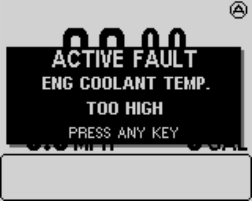
Note: The symbol  at the top right corner of the home screen, an engine advisory
message, or a stop engine message indicates that an active fault exists
for the engine.
at the top right corner of the home screen, an engine advisory
message, or a stop engine message indicates that an active fault exists
for the engine.
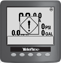
Engine Advisories Messages
If an engine advisory message displays in the InfoCenter, you should stop spraying operation and drive the machine to the maintenance facility. Examples of the advisory screens are as follows:
-
When the engine control unit (ECU) detects an advisory level fault, the engine advisory indicator displays (Figure 36).
-
Stop spraying operation and drive the machine to the maintenance facility.
Note: An Active Fault message displays (Figure 37).
-
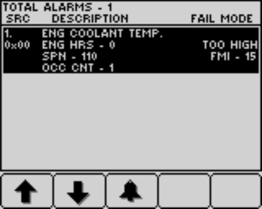
Press button 1 through 5 to view the active fault list (Figure 38).
-
Press button 1 or 2 to navigate up or down the list.
-
Press button 3 to mute the audio alarm.
-
-
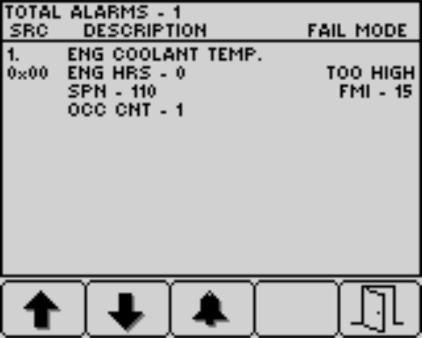
Press button 5 to exit the active fault list and return to the home screen (Figure 39).
Stop Engine Messages
When a stop engine message displays in the InfoCenter, the operator should immediately park the machine and shutoff the engine. Examples of the advisory screens are as follows:
Important: Continued operation of the engine when a stop message displays will result in damage to the engine.
-
When the engine control unit (ECU) detects a severe level fault, the stop engine indicator displays (Figure 40).

-
Immediately park the machine and shutoff the engine.
-
An Active Fault message is next displayed (Figure 41).
-
Press button 1 through 5 to view the active fault list ; refer to Figure 38 in Engine Advisories Messages.
-
Press button 1 or 2 to navigate up or down the list.
-
Press button 3 to mute the audio alarm.
-
-
Press button 5 to exit the active fault list and return to the home screen; refer to Figure 39 in Engine Advisories Messages.
Operating the Sprayer
To operate the sprayer: fill the sprayer tank, apply the product mix to the job site, and clean the tank and spray system. You must complete all 3 of these steps in succession to avoid damaging the sprayer. For example, do not mix and add chemicals in the sprayer tank at night and then spray in the morning. This leads to separation of the chemicals and possible damage to the sprayer components.
Caution
Chemicals are hazardous and can cause personal injury.
-
Read the directions on the chemical labels before handling the chemicals and follow all manufacturer recommendations and precautions.
-
Keep chemicals away from your skin. Should contact occur, wash the affected area thoroughly with soap and clean water.
-
Wear appropriate personal protective equipment (PPE) per the chemical manufacturer’s instructions.
The Multi Pro® Sprayer is specifically designed for high durability, provides the long sprayer life. Different materials have been chosen for specific reasons at different locations on your sprayer to meet this goal. Unfortunately, there is no single material which is perfect for all foreseeable applications.
Some chemicals are more aggressive than others and each chemical interacts differently with various materials. Some consistencies (e.g., wettable powders, charcoal) are more abrasive and lead to higher wear rates. If a chemical is available in a formulation that would provide increased life to the sprayer, use this alternative formulation.
As always, remember to clean your sprayer and spray system thoroughly after all applications. This ensures that your sprayer has a long and trouble-free life.
Note: If you have questions or need additional information regarding the spray-control system, refer to the Operator’s Manual supplied with the system.
Sprayer Functions for Application Rate Mode and Manual Mode
Refer to the Software Guide for the Multi Pro 5800-D and 5800-G turf sprayers with ExcelaRate spray system for information on the following:
Before Operation
-
The InfoCenter home screen
-
The main menu screen
-
The main menu sub-screens
-
The service screens
-
The diagnostic screens
-
The About screens
During Operation
-
Entering job information
-
InfoCenter spray-area screens
-
InfoCenter advisories
Spraying with the ExcelaRate Sprayer System
Refer to the Software Guide for the Multi Pro 5800-D and 5800-G turf sprayers with ExcelaRate spray system for information on the following procedures:
Important: To ensure that the product remains well mixed, use the agitation feature whenever you have solution in the tank.
Spraying in the Application Rate Mode
-
Ensure that the spray system is calibrated for the active spray nozzles that you have selected; Refer to the Software Guide for the Multi Pro 5800-D and 5800-G turf sprayers with ExcelaRate spray system.
-
Rotate the knob for the section-bypass shutoff valve to the closed position (Figure 42).
-
Set the sprayer mode button to the Application Rate Mode (Figure 43).
-
Move the sprayer to the area of turf that you are spraying.
-
If you are collecting area sprayed and volume sprayed data for each job site, select a sub-area screen (sub-areas 1 through 20) to record for the individual area and volume information; refer to Using the Sub-Area Screen in the Software Guide for the Multi Pro 5800-D and 5800-G turf sprayer with ExcelaRate spray system.
Note: When you move to a different job site, you need to select another sub-area screen to record the individual area and volume information.
-
If you need to switch the active rate between the rate 1 value and the rate 2 value, from the InfoCenter home screen press buttons 1 and 2 simultaneously to select RATE 1 or press buttons 4 and 5 simultaneously to select RATE 2; Refer to the Software Guide for the Multi Pro 5800-D and 5800-G turf sprayers with ExcelaRate spray system.
-
Set the spray section switch(es) to the ON position (Figure 44).
-
Set the agitation switch and the spray-pump switch to the ON position (Figure 45).
-
Set the throttle to the FAST position (Figure 45).
-
Drive at the desired speed and then set the master section switch to the ON position to begin spraying (Figure 44).
Note: Use the master section switch to start and stop the flow of chemical s to the selected spray sections.
-
When finished spraying, set the master section switch to the OFF position to turn off all spray sections, then set the spray-pump switch to the OFF position.
Note: Raise the outer spray sections to the transport position and drive the sprayer to the cleaning area.
Important: Always raise the boom sections until they have moved completely into section-transport cradle forming the “X” transport position and the lift cylinders are fully retracted whenever you move the sprayer from 1 spraying area to another, or move to a storage or cleaning area.
Spraying in the Manual Mode
Note: This procedure assumes that the spray pump is on; refer to Figure 45 in Spraying in the Application Rate Mode.
-
Ensure that the sprayer system is adjusted for the active spray nozzles that you have selected; refer to Preparing the Machine.
-
Set the sprayer mode button to the Manual Mode (Figure 46).
-
Set the master section switch to the OFF position; refer to Figure 44 in Spraying in the Application Rate Mode.
-
Adjust the throttle to the desired engine speed to spray; refer to Figure 45 in Spraying in the Application Rate Mode.
-
Drive to the spraying location.
-
Lower the sections into position.
-
Set the individual section switches, as needed, to the ON position; refer to Figure 44 in Spraying in the Application Rate Mode.
-
Use the application-rate switch to achieve the desired spray pressure as indicated in the nozzle-selection guide provided with the sprayer (Figure 47).
-
Drive at the desired speed and then set the master section switch to the ON position to begin spraying; refer to Figure 44 in Spraying in the Application Rate Mode.
Note: When the tank is nearly empty, the agitation may cause foaming in the tank. In this case, turn the agitation switch to the OFF position. Alternatively, you can add anti-foaming agent to the tank.
-
When you are finished spraying, set the master section switch to the OFF position to turn off all sections, then set the spray-pump switch to the OFF position.
Note: Return the sections to the transport position and drive the sprayer to the cleaning area.
Important: Always raise the sections until they have moved completely into section-transport cradle forming the “X” transport position and the section cylinders are fully retracted whenever you move the sprayer from 1 spraying area to another, or move to a storage or cleaning area.
Catch Test
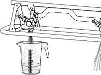
Important: You will need to provide a graduated catch container (a container with 0.01 ml (1/2 fl. oz) increments is preferred) and a stopwatch to complete this procedure.
Preparing for the Catch Test
Important: Whenever possible, do not use reclaimed water (gray water) in the spray tank.
-
Ensure that the sprayer tank is clean; refer to Cleaning the Sprayer System.
-
Fill the sprayer tank with at least 568 L (150 US gallons) of fresh water; refer to Filling the Spray Tank.
-
Ensure that the nozzles that you intend to test are in the active spray (down) position.
-
For machines operated in the application-rate mode, ensure that the knob for the section-bypass shutoff valve is in the closed position (Figure 48).
-
For machines operated in the application-rate mode, ensure that the section-bypass shutoff valve is closed (Figure 48).
-
Engage the parking brake and start the engine.
Note: Allow the engine to warm for 10 minutes.
-
For machines operated in the application-rate mode, perform the steps in Using the Test Speed; refer to the Software Guide for the Multi Pro 5800-D and 5800-G turf sprayers with ExcelaRate spray system.
Note: Set the simulated test speed between 4 km/h (2 mph) and 14 km/h (9 mph).
Performing a Catch Test
-
Set the spray section switch(es) to the ON position for the section(s) that you are testing.
-
Set the throttle to the FAST position.
-
Set the master section switch to the ON position.
-
Perform a 15-second catch test at 1 of the active spray nozzles.
-
Shut off the master section switch, set the throttle to the slow position, shut off the spray pump, and shut off the engine.
-
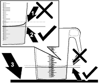
Set the graduated container on a level surface and note the fluid volume (Figure 50).
Important: When you are reading the graduated container, you must set the container on a level surface.
Important: When you are reading the graduated container, read the fluid volume in the graduated container at the lowest point of the fluid-surface curve.
Important: Small errors reading the fluid volume in the graduated container will significantly impact the accuracy of the sprayer calibration.
-
Compare the volume of water in the graduated container with the nozzle volume in the 15-second catch test table.
15-Second Catch Test Table
Nozzle Color Milliliters collected in 15 seconds Ounces collected in 15 seconds Yellow 189 6.4 Red 378 12.8 Brown 473 16.0 Gray 567 19.2 White 757 25.6 Blue 946 32.0 Green 1,419 48.0 -
If the fluid level in the graduated catch container is 7.4 ml (1/4 fl oz) more or less than the nozzle volume in the 15-second catch test table, perform 1 of the following:
-
Perform a flow calibration, or replace worn nozzles and perform a flow calibration; refer to the flow calibration procedure in the Software Guide for the Multi Pro 5800-D and 5800-G turf sprayer with ExcelaRate spray system.
-
Calibrate the agitation bypass valve, or replace worn nozzles and calibrate the agitation bypass valve; refer to Calibrating the Agitation-Bypass Valve.
-
Positioning the Spray Sections
The boom-section lift switches on the sprayer control panel allows you to move the outer spray sections between transport position and spray position without leaving the operator's seat. Whenever possible, stop the machine before changing spray section positions.
Changing the Spray Section Position
Perform the following steps to move the outer spray sections to the SPRAY position:
-
Park the machine on a level surface.
-
Use the boom-section lift switches to lower the outer sections.
Note: Wait until the outer spray sections reach the full, extended spray position.
Complete the sprayer job, then perform the following steps to retract the outer spray sections into the transport position:
Important: If your machine has the Drift Reduction Boom Shroud Kit, the Ultra Sonic Boom Leveling Kit installed, or both move the outer spray sections to the transport position one at a time.Moving both outer spray sections at the same time with the shroud kit or leveling kit installed may damage the shrouds, the sensors, or both.
-
Park the machine on a level surface.
-
Use the boom-section lift switches to raise the outer spray sections, until they have moved completely into boom-section transport cradles forming the “X” transport position, and the lift cylinders are fully retracted.
Important: Release the boom-section lift switch(es) once the outer spray sections have reached the desired position. Running the actuators against the mechanical stops may damage the lift cylinders and/or other hydraulic components.
Important: To prevent damage to the lift cylinder, make sure that the actuators are fully retracted before transporting the machine.
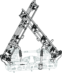
Using the Boom-Section Transport Cradle
The sprayer is equipped with boom-section transport cradles that have a unique feature. In the event the spray section accidentally contacts with a low overhead object while in the transport position, you can push the spray section(s) out of the transport cradles. If this occurs, the spray sections come to rest in a near horizontal position to the rear of the machine. While this movement will not damage the spray sections, they should be immediately positioned into the transport cradle.
Important: The spray sections can be damaged by transporting them in any position other than the “X” transport position using the boom transport cradle.
To put the outer spray sections back into the transport cradle, lower the spray section(s) to the spray position and then raise the spray section(s) back to the transport position. Make sure that the lift cylinders are fully retracted to prevent damaging the actuator rod.
Taking Proper Turf Care Precautions while Operating in Stationary Modes
Important: Under some conditions, heat from the engine, radiator, and muffler can damage grass when operating the sprayer in a stationary mode. Stationary modes include tank agitation, hand spraying with a spray gun, or using a walking boom.
Use the following precautions:
-
Avoid stationary spraying when conditions are very hot and/or dry, as turf can be more stressed during these periods.
-
Avoid parking on the turf while stationary spraying. Park on a cart path whenever possible.
-
Minimize the amount of time the machine is left running over any particular area of turf. Both time and temperature affect how much the grass may be damaged.
-
Set the engine speed as low as possible to achieve the desired pressure and flow. This minimizes the heat generated and the air velocity from the cooling fan.
-
Allow heat to escape upward from the engine compartment by raising the seat assemblies during stationary operation rather than being forced out under the vehicle.
Spraying Tips
-
Do not overlap areas that you have previously sprayed.
-
Watch for plugged nozzles. Replace all worn or damaged nozzles.
-
Use the master section switch to stop the spray flow before stopping the sprayer. Once it stops, use the engine-throttle control to hold the engine speed up to keep the agitation running.
-
You will obtain better results if the sprayer is moving when you turn the spray sections on.
Unclogging a Nozzle
If a nozzle becomes clogged while you are spraying, clean the nozzle as follows:
-
Stop the sprayer on a level surface, shut off the engine, and engage the parking brake.
-
Set the master section switch to the OFF position and then set the sprayer-pump switch to the OFF position.
-
Remove the clogged nozzle and clean it using a spray bottle of water and a toothbrush.
-
Install the nozzle.
After Operation
After Operation Safety
General Safety
-
Before you leave the operator’s position, do the following:
-
Park the machine on a level surface.
-
Move the traction pedal to the NEUTRAL position.
-
Shut off the spray pump.
-
Engage the parking brake.
-
Shut off the engine and remove the key (if equipped).
-
Wait for all movement to stop.
-
Allow the machine to cool before adjusting, servicing, cleaning, or storing it.
-
-
After you finish operating the machine for the day, wash off all chemical residue from the outside of the machine and ensure that the system has been neutralized and triple rinsed according to the recommendations of the chemical manufacturer(s) and that all the valves have been cycled 3 times; refer to Chemical Safety.
-
Allow the engine to cool before storing the machine in any enclosure.
-
Never store the machine or fuel container where there is an open flame, spark, or pilot light, such as on a water heater or other appliance.
-
Keep all parts of the machine in good working condition and all hardware tightened.
-
Replace all worn, damaged, or missing decals.
Cleaning the Sprayer
Wash the machine as needed using water alone or with a mild detergent. You may use a rag when washing the machine.
Important: Do not use brackish or reclaimed water to clean the machine.
Note: Do not use power-washing equipment to wash the machine. Power-washing equipment may damage the electrical system, loosen important decals, or wash away necessary grease at friction points. Avoid excessive use of water near the control panel, engine, and battery.
Important: Do not wash the machine with the engine running. Washing the machine with the engine running may result in internal engine damage.
Cleaning the Sprayer System
Draining the Tank
-
Stop the sprayer, engage the parking brake, shut off the engine, and remove the key.
-
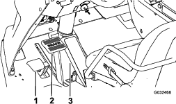
Locate the tank-drain valve at the left, rear fender of the machine (Figure 52).
Note: The drain valve is attached to the drain-valve bracket that is mounted to the left, rear fender.
-
Lift the valve until the mount studs of the valve clear the slots in the drain-valve bracket, and move the valve rearward (Figure 53A).
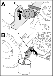
-
Align the end of the valve with the drain container and rotate valve handle to the open position (Figure 53B).
-
When the tank has drained completely, rotate the drain-valve handle to the closed position and assemble the valve onto the drain-valve bracket (Figure 53B and Figure 53A).
Important: Dispose of the sprayer tank chemicals according to local codes and the material manufacturer's instructions.
Cleaning Internal Sprayer Components
| Maintenance Service Interval | Maintenance Procedure |
|---|---|
| After each use |
|
Important: Use only clean water when cleaning the sprayer.
Important: You must always drain and flush out the sprayer, including any installed spray system accessories immediately after each use. Failure to flush and clean the sprayer may allow the chemicals to dry and obstruct in the lines, filters, valves, nozzle bodies, pump, and other components.
Toro recommends using the approved Clean Rinse Kit for this machine. Contact your authorized Toro distributor for more information.
Note: The recommendations and instructions that follow assume that the Toro Rinse Kit is not installed.
Clean the spray system and any installed spray accessories after each spraying session. To properly clean the spray system, perform the following:
-
Complete 3 separate rinse cycles.
-
Use the cleaners and neutralizers as recommended by your chemical manufacturers.
-
Use pure, clean water (no cleaners or neutralizers) for the final rinse.
-
Fill the tank with at least 190 L (50 US gallons) of clean water and close the cover.
Note: You can use a cleaning/neutralizing agent in the water as needed. On the final rinse, use only clean, clear water.
-
Lower the outer spray sections into the spray position.
-
Start the engine, set the spray pump switch to the ON position, and move the throttle lever to a high-engine speed.
-
Set the agitation switch to the ON position.
-
Use the application-rate switch to increase the pressure to a high setting.
-
Set the individual section switches and master section switch to the ON positions.
-
Check the nozzles to ensure that they are all spraying correctly.
-
Allow all water in the tank to spray out through the nozzles.
-
Set the master section switch to the OFF position, the set the agitation switch and spray-pump switch to the OFF position, and shut off the engine.
-
Repeat steps 1 through 9 at least 2 more times to ensure that the spray system is fully cleaned.
Important: You must always complete 3 rinse cycles to ensure that the spray system and spray accessories are fully clean, preventing damage to the system.
Cleaning External Sprayer Components
-
Clean the suction and pressure filters; refer to Cleaning the Suction Filter and Cleaning the Pressure Filter.
Important: If you used wettable powder chemicals, clean the strainer after each tank.
-
Using a garden hose, rinse off the outside of the sprayer with clean water.
-
Remove the nozzles and clean them by hand.
Note: Replace damaged or worn nozzles.
Note: If your machine has optional nozzle filters, clean them before installing the nozzles; refer to Cleaning the Nozzle Filter.
Cleaning the Suction Filter
| Maintenance Service Interval | Maintenance Procedure |
|---|---|
| Before each use or daily |
|
-
Park the machine on a level surface, engage the parking brake, shut off the pump, shut off the engine, and remove the key.
-
At the top of the sprayer tank, remove the retainer that secures the hose fitting attached to the large hose from the filter housing (Figure 54).
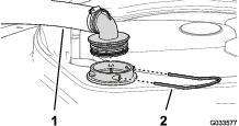
-
Remove the hose and hose fitting from the filter housing (Figure 54).
-
Pull the suction strainer out of the filter housing in the tank (Figure 55).
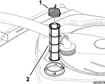
-
Clean the suction filter with clean water.
Important: Replace the filter if it is damaged or cannot be cleaned.
-
Insert the suction filter into the filter housing until the filter is fully seated.
-
Align the hose and hose fitting to the filter housing at the top of the tank, and secure fitting and housing with the retainer that you removed in step 2.
Cleaning the Pressure Filter
| Maintenance Service Interval | Maintenance Procedure |
|---|---|
| Before each use or daily |
|
-
Park the machine on a level surface, engage the parking brake, shut off the sprayer pump, shut off the engine, and remove the key.
-
Align a drain pan under the pressure filter (Figure 56).
-
Rotate the drain cap counterclockwise and remove it from the bowl of the pressure filter (Figure 56).
Note: Allow the bowl to drain completely.
-
Rotate the bowl counterclockwise and remove the filter head (Figure 56).
-
Remove the pressure filter element (Figure 56).
-
Clean the pressure filter element with clean water.
Important: Replace the filter if it is damaged or cannot be cleaned.
-
Check the gasket for the drain plug (located inside the bowl) and the gasket for bowl (located inside the filter head) for damage and wear (Figure 56).
Important: Replace any damaged or worn gaskets for the plug, bowl, or both.
-
Install the pressure filter element into the filter head (Figure 56).
Note: Ensure that the filter element is firmly seated into the filter head.
-
Install the bowl onto the filter head, and tighten by hand (Figure 56).
-
Assemble the drain cap onto the fitting at the bottom of the bowl, and tighten the cap by hand (Figure 56).
Cleaning the Nozzle Filter
-
Park the machine on a level surface, engage the parking brake, shut off the sprayer pump, shut off the engine, and remove the key.
-
Remove the nozzle from the spray turret (Figure 57).
-
Remove the nozzle filter (Figure 57).
-
Clean the nozzle filter with clean water.
Important: Replace the filter if it is damaged or cannot be cleaned.
-
Install the nozzle filter (Figure 57).
Note: Ensure that the filter is fully seated.
-
Install the nozzle onto the spray turret (Figure 57).
Conditioning the Spray System
| Maintenance Service Interval | Maintenance Procedure |
|---|---|
| After each use |
|
Conditioner Specification
Conditioner specification: propylene glycol "non-toxic RV antifreeze” with corrosion inhibitor
Important: Use only propylene glycol with corrosion inhibitor. Do not use recycled propylene glycol. Do not use ethylene glycol base antifreeze.Do not use propylene glycol with soluble alcohols (methanol, ethanol, or isopropanol) or brines added.
Preparing the Conditioner
-
Move the machine to a level surface, set the parking brake, shut off the engine, and remove the key.
-
Add conditioner to the tank as follows:
-
For ready to use (premixed) propylene glycol RV antifreeze—add 10 gallons of propylene glycol RV antifreeze to the tank.
-
For concentrated propylene glycol RV antifreeze, perform the following steps:
-
Add a 10-gallon mixture of propylene glycol RV antifreeze and water into the sprayer tank. Prepared the antifreeze mixture as instructed manufacturer for a concentration rated for -45°C (-50°F) minimum.
Important: Use only clean water when cleaning the sprayer.
-
Start the engine and set the spray-pump switch to the ON position.
-
Press the accelerator pedal to increase the engine speed.
-
Set the agitation switch to the ON position.
Allow the conditioner and water solution to circulate for 3 minutes or longer.
-
-
Spraying the Conditioner
Recommended tool: a clear catch container.
-
Move the machine to the drain pad area and set the parking brake.
-
Lower the outer booms sections.
-
Set the left, center, and right section switches and the master section switch to the ON position.
-
Allow the spray system to spray until the nozzles discharge the conditioner.
Note: Most propylene glycol RV antifreeze is colored pink. Use the catch container to sample the sprayer discharge at several of the nozzles.
-
Shut off the master section switch, 3 section switches, agitation switch, spray-pump switch, and engine.
Hauling the Machine
Use a trailer or truck when moving the machine long distances.
Towing the Sprayer
In case of an emergency, the sprayer can be towed for a short distance after you open the tow valve. However, we do not recommend this as a standard procedure.
Warning
Towing at excessive speeds could cause a loss of steering control, resulting in personal injury.
Never tow the sprayer at faster than 4.8 kph (3 mph).
Towing the sprayer is a 2-person job. If the machine must be moved a considerable distance, transport it on a truck or trailer; refer to Hauling the Machine.
-
Allow the exhaust system to cool completely.
-
Remove the undercarriage shroud; refer to Removing the Undercarriage Shroud.
-
Rotate the tow valve (Figure 60) 90° in either direction to open the tow valve.
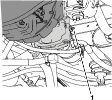
Important: If you do not open the tow valve before towing the sprayer, you will damage the transmission.
-
Affix a tow line to the frame; refer to the front and rear towing points (Figure 61 and Figure 62).
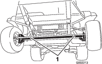
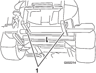
-
Release the parking brake.
-
Tow the sprayer at less than 4.8 kph (3 mph).
-
When finished, close the tow valve and torque it to 7 to 11 N∙m (5 to 8 ft-lb).
Important: Before returning the machine to service, install the undercarriage shroud; refer to Installing the Undercarriage Shroud.
Maintenance
Note: Download a free copy of the electrical or hydraulic schematic by visiting www.Toro.com and searching for your machine from the Manuals link on the home page.
Important: Refer to your engine owner’s manual for additional maintenance procedures.
Note: Determine the left and right sides of the machine from the normal operating position.
Maintenance Safety
-
Before you leave the operator’s position, do the following:
-
Park the machine on a level surface.
-
Move the traction pedal to the NEUTRAL position.
-
Engage the parking brake.
-
Shut off the engine and remove the key (if equipped).
-
Wait for all movement to stop.
-
-
Allow machine components to cool before performing maintenance.
-
Allow only qualified and authorized personnel to maintain, repair, adjust, or inspect the machine.
-
Before performing any maintenance, thoroughly clean and rinse the sprayer; refer to Chemical Safety.
-
Chemicals used in the sprayer system may be hazardous and toxic to you, bystanders, animals, plants, soils, or other property.
-
Carefully read and follow the chemical warning labels and safety data sheets (SDSs) for all chemicals used, and protect yourself according to the chemical manufacturer’s recommendations.
-
Always protect your skin while you are near chemicals. Use the appropriate personal protective equipment (PPE) to guard against contact with chemicals, including the following:
-
safety glasses, goggles, and/or face shield
-
a chemical suit
-
a respirator or filter mask
-
chemical-resistant gloves
-
rubber boots or other substantial footwear
-
a clean change of clothes, soap, and disposable towels for cleanup
-
-
Refuse to operate or work on the sprayer if chemical safety information is not available.
-
Do not fill, calibrate, or clean the machine while people, especially children, or pets are in the area.
-
Handle chemicals in a well-ventilated area.
-
Have clean water available, especially when filling the spray tank.
-
Do not eat, drink, or smoke while working near chemicals.
-
Do not clean spray nozzles by blowing through them or placing them in your mouth.
-
Always wash your hands and other exposed areas as soon as possible after working with chemicals.
-
Chemicals and fumes are dangerous; never enter the tank or place your head over or in the opening of a tank.
-
-
To ensure that the entire machine is in good condition, keep all hardware properly tightened.
-
To reduce the potential for fire, keep the engine area free of excessive grease, chemicals, grass, leaves, and dirt.
-
If you must run the engine to perform a maintenance adjustment, keep your hands, feet, clothing, and any parts of your body away from the engine and any moving parts. Keep everyone away.
-
Do not adjust the ground speed of the machine. To ensure safety and accuracy, have an authorized Toro distributor check the ground speed.
-
If the machine requires a major repair or you need technical help, contact an authorized Toro distributor.
-
Modifying this machine in any manner may affect machine operation, performance, durability, or its use, and result in injury or death. Such use could void the product warranty.
-
Support the machine with jack stands whenever you work under the machine.
-
Carefully release pressure from components with stored energy.
Recommended Maintenance Schedule(s)
| Maintenance Service Interval | Maintenance Procedure |
|---|---|
| After the first 8 hours |
|
| After the first 50 hours |
|
| After the first 100 hours |
|
| After the first 200 hours |
|
| Before each use or daily |
|
| After each use |
|
| Every 50 hours |
|
| Every 100 hours |
|
| Every 200 hours |
|
| Every 400 hours |
|
| Every 800 hours |
|
| Every 1,000 hours |
|
| Every 2,000 hours |
|
| Yearly |
|
Notation for Areas of Concern
| Inspection performed by: | ||
| Item | Date | Information |
| 1 | ||
| 2 | ||
| 3 | ||
| 4 | ||
| 5 | ||
| 6 | ||
| 7 | ||
| 8 | ||
| 9 | ||
| 10 | ||
Pre-Maintenance Procedures
Caution
If you leave the key in the starter switch, someone could accidently start the engine and seriously injure you or other bystanders.
Remove the key from the starter switch before you do any maintenance.
Raising the Sprayer
Whenever running the engine for routine maintenance and/or engine diagnostics, the rear wheels of the sprayer should be 25 mm (1 inch) off the ground with the rear axle supported on jack stands.
Danger
A sprayer on a jack may be unstable and slip off the jack, injuring anyone beneath it.
-
Always remove the key from the starter switch before getting off the sprayer.
-
Block the tires when the sprayer is on a jack.
-
Support the machine with jack stands.
The jacking point at the front of the sprayer is under the front axle, directly under the leaf springs (Figure 63).
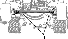
The jacking point at the rear of the sprayer is on the rear side where the boom supports are located (Figure 64).
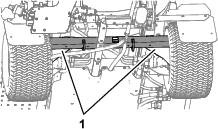
Accessing the Engine
Removing the Forward Heat Shield
-
Engage the parking brake, shut off the spray pump, shut off the engine, and remove the key.
-
Raise the front and back of the machine and support it with jack stands; refer to Raising the Sprayer.
-
Remove the 6 hex-head bolts and 6 washers that secure the front, forward heat shield to the chassis and remove the shield (Figure 65).
Note: Retain the bolts, washers, and heat shield for installation in Installing the Forward Heat Shield.
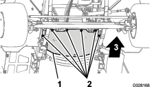
Installing the Forward Heat Shield
-
Align the rear flange of the forward heat shield over the forward flange of the rear heat shield (Figure 66).
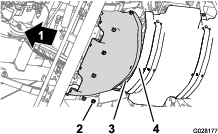
-
Align the holes in the forward heat shield with the threaded holes in the chassis (Figure 66).
-
Assemble the forward heat shield to the machine with the 6 hex-head bolts and 6 washers (Figure 66) that you removed in step 3 of Removing the Forward Heat Shield.
-
Torque the bolts to 1978 to 2542 N∙cm (175 to 115 in-lb).
-
Remove the jack stands and lower the machine.
Removing the Undercarriage Shroud
-
Remove the 5 flange-head bolts (5/16 x 7/8 inch) and 5 washers (5/16 inch) that secure the rear of the undercarriage shroud to the chassis of the machine (Figure 67).
Note: Retain the flange-head bolts and washers for installation in step 5 of Installing the Undercarriage Shroud.
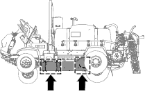
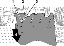
-
Remove the 4 flange locknuts (5/16 inch) from the bolts and carriage bolt that secure the mounting tabs of the undercarriage shroud to the engine-mount brackets of the machine (Figure 68).
Note: Do not remove the bolts from the machine. Retain the flange locknuts for installation in step 3 of Installing the Undercarriage Shroud.
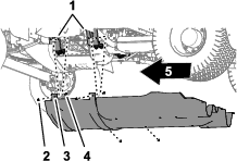
-
Move the mounting tabs off the bolts that secure the undercarriage shroud to the engine-mount brackets.
-
Remove the undercarriage shroud from the machine (Figure 67 and Figure 68).
Installing the Undercarriage Shroud
-
Align the undercarriage shroud to the bottom chassis of the machine; refer to Figure 68 in Removing the Undercarriage Shroud.
-
Move the mounting tabs of the undercarriage shroud over the bolts and carriage bolt at the engine-mount brackets of the machine; refer to Figure 68 in Removing the Undercarriage Shroud.
-
Assemble the undercarriage shroud to the engine-mount brackets and bolts (Figure 68) with the 4 flange locknuts (5/16 inch) that you removed in step 2 of Removing the Undercarriage Shroud.
-
Align the holes in the rear part of the undercarriage shroud with the holes in the chassis; refer to Figure 67 in Removing the Undercarriage Shroud.
-
Assemble the rear part of the undercarriage shroud to the chassis (Figure 67) with the 5 flange-head bolts (5/16 x 7/8 inch) and 5 washers (5/16 inch) that you removed in step 1 of Removing the Undercarriage Shroud.
-
Torque the nuts and bolts to 1129 to 1582 N∙cm (100 to 140 in-lb).
Removing the Seat-Base-Access Panel

Installing the Seat-Base-Access Panel
-
Align the holes in the seat-base-access panel with the holes in the seat base (Figure 69).
-
Assemble the seat-base-access panel to the seat base with the 2 flanged-head bolts (Figure 69) that you removed in step 1 of Removing the Seat-Base-Access Panel.
-
Torque the bolts to 1975 to 2542 N∙cm (175 to 225 in-lb).
Lubrication
Greasing the Spray Pump
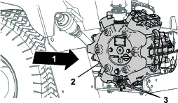
Greasing the Steering and Suspension
| Maintenance Service Interval | Maintenance Procedure |
|---|---|
| Every 50 hours |
|
Grease Type: No. 2 lithium grease. Toro Premium All-Purpose Grease is available from your authorized Toro distributor.
-
Steering cylinder—2 grease fittings at each rod end of the cylinder
-
Steering rod—2 grease fittings at each rod end
-
Spindle pivot—2 grease fittings at each side of the machine
-
Pump grease into the grease fittings (Figure 71 and Figure 72).
-
Wipe off excess grease.
Note: The grease fittings positions are illustrated in Figure 71.
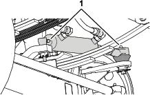
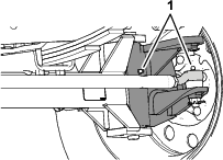
Greasing the Boom Hinges
| Maintenance Service Interval | Maintenance Procedure |
|---|---|
| Every 100 hours |
|
Important: If you wash the boom hinges with water, remove all water and debris from the hinge assembly and apply fresh grease.
Grease Type: No. 2 lithium grease.
-
Wipe the grease fittings clean so that foreign matter cannot be forced into the bearing or bushing.
-
Pump grease into the bearing or bushing at each fitting (Figure 73).
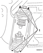
-
Wipe off excess grease.
-
Repeat the procedure for each boom pivot.
Greasing the Actuator-Rod Bearings
| Maintenance Service Interval | Maintenance Procedure |
|---|---|
| Every 400 hours |
|
Grease Type: No. 2 lithium grease.
-
Lower the outer spray sections to the SPRAY position.
-
Remove the hairpin from the clevis pin (Figure 74).
-
Lift up on the section, remove the clevis pin, and slowly lower the section to the ground (Figure 74).
-
Inspect the clevis pin for damage, and replace it if necessary.
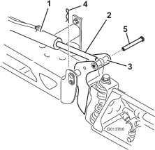
-
Swivel the rod-end bearing and apply grease into the bearing (Figure 75).
Note: Wipe off excess grease.
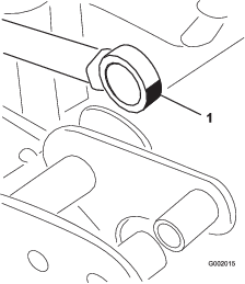
-
Lift the spray section to align the pivot with the actuator rod.
-
While supporting the spray section, insert the clevis pin through both boom pivot and actuator rod (Figure 74).
-
With the pin in place, release the spray section and secure the clevis pin with the hairpin removed previously.
-
Repeat steps 2 through 8 to the actuator-rod bearing at the other side of the machine.
Engine Maintenance
Engine Safety
Shut off the engine before checking the oil or adding oil to the crankcase.
Checking the Air Cleaner
| Maintenance Service Interval | Maintenance Procedure |
|---|---|
| Before each use or daily |
|
-
Engage the parking brake, shut off the spray pump, shut off the engine, and remove the key.
-
Tilt the passenger seat forward and align the prop rod into the detent in the prop-rod-guide slot.
-
Clean the dust cap and air-cleaner body (Figure 76).
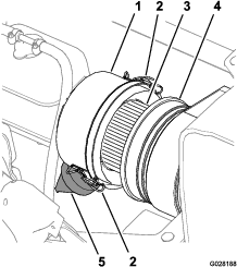
-
Check the air-cleaner body for damage that could cause an air leak (Figure 76).
Note: Replace the dust cap and air-cleaner body if either is damaged.
-
Squeeze the dust valve to clear it of dirt, dust, and debris (Figure 76).
-
Loosen the 2 latches that secure the dust cap to the air-cleaner body.
-
Check the air-filter element for excessive accumulation of dust, dirt, and debris (Figure 76).
Note: Do not clean the air-filter element if it is dirty; replace the air-filter element if it is dirty.
-
Install the dust cap onto the air-cleaner body and secure the cap with the 2 latches (Figure 76).
Note: Ensure that the dust valve aligns between the 5 to 7 o’clock position when viewed from the end.
-
Lower the passenger seat.
Replacing the Air-Filter Element
| Maintenance Service Interval | Maintenance Procedure |
|---|---|
| Every 100 hours |
|
-
If you are installing a new filter, inspect the new air-filter element for shipping damage, including the sealing end of the filter.
Important: Do not install a damaged filter.
-
Clean the dust cap and air-cleaner body (Figure 76).
-
Lift the coolant-overflow tank up and off the tank-support bracket (Figure 77).
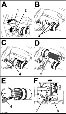
-
Loosen the 2 latches that secure the dust cap to the air-cleaner body (Figure 77).
-
Gently slide the old filter element out of the air-cleaner body to reduce the amount of dust dislodged.
Note: Avoid knocking the filter element against the air-cleaner body.
-
Clean the inside of the dust cap, air-cleaner body, and dust valve with a damp rag (Figure 76 and Figure 77).
-
Insert the air-filter element into the air-cleaner body (Figure 77).
Note: Ensure that the filter is seated in the air-cleaner body properly by applying pressure to the outer rim of the filter element when you install it. Do not press on the flexible center part of the filter.
-
Install the cover onto the air-cleaner body and secure the cover with the 2 latches (Figure 77).
Note: Ensure that the dust valve is aligned between the 5 to 7 o’clock position when viewed from the end (Figure 77).
-
Align the coolant-overflow tank to the tank-support bracket and seat the tank firmly (Figure 77).
Important: Ensure that the pressure-relief hose is routed forward and down, and the tank-vent hose is routed rearward as shown in Figure 77.
-
Lower the passenger seat.
Engine-Oil Specification
-
Oil type: API service classification SL or higher.
-
Oil viscosity: refer to the engine oil viscosity table below.
Engine Oil Viscosity Table
Ambient temperature range Oil viscosity Above 25°C (77°F) SAE30, SAE10W-30, or SAE15W-40 0°C to 25°C (32°F to 77°F) SAE20 or SAE10W-30 0°C to 20°C (32°F to -4°F) SAE10W or SAE10W-30
Toro Premium Engine Oil is available from your distributor in either 15W40 or 10W30 viscosity. Refer to the Parts Catalog for part numbers.
Checking the Engine Oil
| Maintenance Service Interval | Maintenance Procedure |
|---|---|
| Before each use or daily |
|
Note: The best time to check the engine oil is when the engine is cool, before it has been started for the day. If the engine was operated, allow the oil to drain back down to the sump for at least 10 minutes before checking.
The engine is shipped with oil in the crankcase; however, the level of oil must be checked before you first start the engine and after you have run it.
-
Position the machine on a level surface.
-
Remove the dipstick, located under the passenger seat, and wipe it with a clean rag (Figure 78).
Note: Insert the dipstick into the tube and make sure it is seated fully. Remove the dipstick and check the oil level.
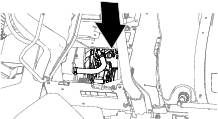
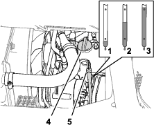
-
If the oil level is low, remove the filler cap from the valve cover (Figure 78) and pour oil into the filler neck until the oil level is up to the Full mark on the dipstick.
Note: Add the oil slowly and check the level often during this process. Do not overfill.
-
Install the oil-filler cap (Figure 78).
-
Install the dipstick firmly in place (Figure 78).
Changing the Engine Oil Filter
| Maintenance Service Interval | Maintenance Procedure |
|---|---|
| After the first 50 hours |
|
| Every 200 hours |
|
-
Remove the forward heat shield; refer to Removing the Forward Heat Shield.
-
Raise the seats.
Caution
Components under the seat will be hot if the sprayer has been running. If you touch hot components, you may be burned.
Allow the sprayer to cool before performing maintenance or touching components under the hood.
-
Align a drain pan under the engine oil filter (Figure 79).
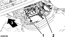
-
Remove the old oil filter (Figure 79).
Note: Dispose of the used oil filter at a certified recycling center.
-
Wipe clean the surface of the oil filter adapter of the engine with a rag.
-
Fill the oil filter with the specified oil.
Note: Allow the filter element to saturate with oil.
-
Apply a thin coat of the specified oil to the rubber gasket on the replacement oil filter.
-
Install the oil filter to the filter adapter and turn the oil filter clockwise until the rubber gasket contacts the filter adapter, then tighten the filter an additional 1/2 turn (Figure 79).
Note: Do not overtighten the oil filter.
-
Wipe clean any residual oil.
Engine-Oil Quantity
5.1 L (5.4 US qt) with the filter; refer to Engine-Oil Specification
Changing the Engine Oil
| Maintenance Service Interval | Maintenance Procedure |
|---|---|
| After the first 50 hours |
|
| Every 200 hours |
|
-
Align a drain pan under the drain plug (Figure 79).
-
Remove the drain plug (Figure 79) and allow the oil to drain completely.
Note: Check the drain plug seal for wear and damage; replace the seal if it is worn or damaged.
Note: Dispose of the used oil at a certified recycling center.
-
Install the drain plug into the drain port of the engine oil pan and tighten the plug to 33 to 37 N∙m (24 to 27 ft-lb).
-
Tilt the passenger seat forward and align the prop rod into the detent in the prop-rod-guide slot.
-
Remove the oil-filler cap from the filler neck of the valve cover of the engine (Figure 80) and slowly pour approximately 80% of the specified amount of oil into the filler neck.
-
Remove the dipstick and check the oil level in the engine (Figure 80).
-
Slowly add additional specified oil to bring the oil level to the full mark on the dipstick (Figure 80).
Important: Overfilling the engine with oil may cause damage to the engine.
-
Install the oil-filler cap into the filler neck and the dipstick into the dipstick tube (Figure 80).
-
Start the engine and check for oil leaks.
-
Shut off the engine, wait 2 to 3 minutes, remove the dipstick, and check the oil level in the engine.
Note: If needed, remove the oil-filler cap, add the specified oil to bring the oil level to the full mark on the dipstick, and install the oil-filler cap.
-
Install the dipstick, engine heat shield, and tilt the seats down.
Checking the PCV Valve
| Maintenance Service Interval | Maintenance Procedure |
|---|---|
| Every 1,000 hours |
|
-
Tilt the driver’s seat forward and align the prop rod into the detent in the prop-rod-guide slot.
-
Remove the PCV valve from the fitting of the valve cover (Figure 81).
Note: Do not separate the hose from the PCV valve.
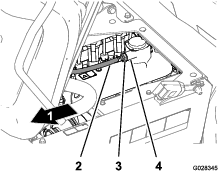
-
Shake the PCV valve.
Note: If the internal restrictor of the valve rattles, the PCV valve is serviceable; if the internal restrictor is not free to rattle when shaken, replace the PCV valve (Figure 81).
-
Insert the PCV valve until it is fully seated in the seal for the valve-cover fitting (Figure 81).
-
Lower the operator’s seat.
Performing Yearly Engine Maintenance
| Maintenance Service Interval | Maintenance Procedure |
|---|---|
| Every 400 hours |
|
Complete all yearly maintenance procedures specified in the engine owner's manual.
Fuel System Maintenance
Danger
Under certain conditions, fuel and fuel vapors are highly flammable and explosive. A fire or explosion from fuel can burn you and others and can cause property damage.
-
Use a funnel and fill the tank outdoors, in an open area, when the engine is off and is cold. Wipe up any spilled fuel.
-
Do not fill the fuel tank completely full. Add fuel to the fuel tank until the level is 25 mm (1 inch) below the bottom of the filler neck. This empty space in the tank allows the fuel to expand.
-
Never smoke when handling fuel, and stay away from an open flame or where fuel fumes may be ignited by a spark.
-
Store fuel in a clean, safety-approved fuel container and keep the cap in place.
Checking the Fuel Line and Connections
| Maintenance Service Interval | Maintenance Procedure |
|---|---|
| After the first 50 hours |
|
| Every 400 hours |
|
Inspect the lines and fittings for deterioration, damage, or loose connections.
Note: If you find any fuel leaks, repair the fuel component(s) before operating the machine.
Bleeding the Fuel System
Use this procedure after you have serviced the fuel filter or ran the engine out of fuel, and the engine does not start.
-
Ensure that you have 1/2 tank of fuel in the fuel tank.
-
Insert the key into the starter switch and rotate it to the ON position.
-
Rotate the key to the OFF position.
-
Attempt to start the engine.
-
If the engine does not start, repeat steps 2 and 3 several times and then attempt to start the engine.
Note: Repeat step 5 until the engine starts.
Servicing the Fuel Filter
| Maintenance Service Interval | Maintenance Procedure |
|---|---|
| Every 400 hours |
|
Removing the Fuel Pump Cover
-
Engage the parking brake, stop the spray pump, stop the engine, and remove the key.
-
At the fuel tank, remove the 4 screws (#10 x 3/4 inch) that secure the cover to the top of the fuel tank, and remove the cover (Figure 82).
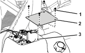
Removing the Carbon Canister
Machine Model 41394
-
Engage the parking brake, stop the spray pump, stop the engine, and remove the key.
-
At the fuel tank, remove the 4 screws (#10 x 3/4 inch) that secure the carbon-canister bracket to the top of the fuel tank (Figure 83).
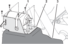
-
Loosen the 2 hose clamps that secure the hoses to the fittings of the carbon canister (Figure 84).
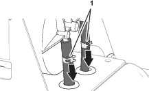
-
Separate the hoses from the fittings (Figure 85).
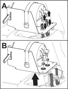
-
Remove the hose clamps from the hoses (Figure 85).
-
Remove the carbon canister from the fuel tank (Figure 85).
Removing the Fuel Pump and Sending Unit
-
Disconnect the 2-socket connector of the machine-wiring harness from the 2-pin connector of the fuel pump/sending unit; disconnect the 2-pin connector of the machine-wiring harness from the 2-socket connector of the fuel pump/sending unit (Figure 86).
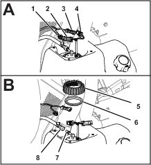
-
Slide the locking sleeve of the fuel-hose coupling away from the fitting of the fuel pump/sending unit and remove the coupling and hose from the fitting (Figure 86).
Note: Clean up any fuel that flows from the hose coupling or fuel-pump fitting.
-
Rotate the nut for the fuel pump/sending unit counterclockwise and remove the nut and seal (Figure 86)
-
Carefully lift and rotate the fuel pump/sending unit out of the neck of the fuel tank (Figure 87).
Important: Use caution when handling the fuel pump/sending unit to avoid damaging the arm for the float of the sending unit.
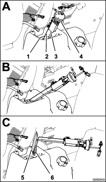
Replacing the Fuel Filter
-
Remove the pickup tube of the fuel filter from the fitting of the fuel pump (Figure 88).
Note: Discard the fuel filter.
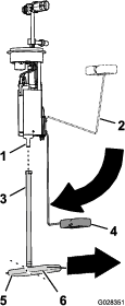
-
Align the pickup tube of the new fuel filter with the fitting of the fuel pump (Figure 88).
-
Align the long leg of the fuel filter with float when the float arm is in the empty position (Figure 88).
-
Insert the fuel-pump fitting into the pickup tube until the fitting is fully seated (Figure 88).
Installing the Fuel Pump and Sending Unit
-
Support the float arm and pickup tube together and slip the float and fuel filter into the opening in the fuel tank (Figure 87).
Important: Ensure that the float and the long leg of the filter are pointing forward in the tank and the fitting at the top of the fuel pump points 90° toward the centerline of the machine.
-
Seat the fuel pump/sending unit into the opening in the tank (Figure 87 and Figure 88).
-
Install the seal and nut over the fuel pump/sending and onto the neck of the fuel tank and tighten the nut hand tight (Figure 87).
-
Connect the coupling on the fuel hose to the fitting of the fuel pump (Figure 87).
Note: Ensure that the locking sleeve of the fuel-hose coupling secures the coupling to the pump fitting.
-
Connect the 2-socket connector of the machine-wiring harness to the 2-pin connector of the fuel pump/sending unit; Connect the 2-pin connector of the machine-wiring harness to the 2-socket connector of the fuel pump/sending unit (Figure 87).
-
Rotate the starter switch to the ON position and check the fuel-hose coupling for leaks.
Note: If the coupling leaks, rotate the starter switch to the OFF position, remove the key, remove the coupling, check the coupling and fitting for dirt or damage, and install the hose and coupling onto the fitting.
Note: Repair any fuel leaks before proceeding to the next step.
Installing the Fuel Pump Cover
-
Assemble the cover to the tank (Figure 89) with the 4 screws (#10 x 3/4 inch) that you removed in step 2 of Removing the Fuel Pump Cover.
-
Torque the screws to 113 N∙cm (10 in-lb).
Installing the Carbon Canister
Machine Model 41394
-
Align the fuel tank hoses through the grommets of the carbon-canister bracket (Figure 90).
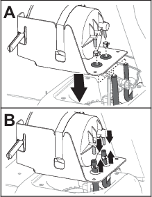
-
Assemble the hose clamps over the hoses (Figure 90).
-
Assemble the hoses onto the fittings of the carbon canister (Figure 90).
-
Secure the hoses to the fittings with the clamps (Figure 91)
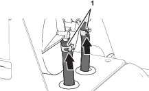
-
Align the holes in the carbon-canister bracket with the holes in the fuel tank (Figure 92).
-
Assemble the bracket to the tank (Figure 92) with the 4 screws (#10 x 3/4 inch).
-
Torque the screws to 113 N∙cm (10 in-lb).
Draining the Fuel Tank
| Maintenance Service Interval | Maintenance Procedure |
|---|---|
| Every 400 hours |
|
Drain and clean the fuel tank if the fuel system becomes contaminated or if you plan to store the machine for an extended period. When cleaning the fuel tank, use fresh, clean fuel to flush out the tank.
-
Transfer the fuel from the tank into an approved fuel container using a siphon pump. Transfer the fuel from the machine before you pour any remaining fuel in the tank through the fill spout, and into a fuel container.
Note: If you decide to remove the fuel tank, you will need to disconnect the fuel hose and electrical connectors from the fuel pump and sending unit; refer to Removing the Fuel Pump and Sending Unit.
-
Flush the tank with fresh, clean fuel, if necessary.
-
Replace the fuel filters; refer to Replacing the Fuel Filter.
-
Install the tank if you removed it in step 1.
Note: If you removed the fuel tank, you will need to connect the fuel hose and electrical connectors to the fuel pump and sending unit ; refer to Installing the Fuel Pump and Sending Unit.
-
Fill the tank with fresh, clean fuel.
Electrical System Maintenance
Electrical System Safety
-
Disconnect the battery before repairing the machine. Disconnect the negative terminal first and the positive last. Connect the positive terminal first and the negative last.
-
Charge the battery in an open, well-ventilated area, away from sparks and flames. Unplug the charger before connecting or disconnecting the battery.
-
Wear protective clothing and use insulated tools.
Replacing the Fuses
The fuse block for the electrical system is located beneath the operator's seat (Figure 93).
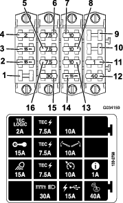
Servicing the Battery
| Maintenance Service Interval | Maintenance Procedure |
|---|---|
| Every 50 hours |
|
Always keep the battery clean and fully charged. Use a paper towel to clean the battery and battery box. If the battery terminals are corroded, clean them with a solution of 4 parts water and 1 part baking soda. Apply a light coating of grease to the battery terminals to prevent corrosion.
Voltage: 12 V with 690 cold cranking amps at 0°F (-18°C)
Removing the Battery
-
Position the sprayer on a level surface, engage the parking brake, shut off the spray pump, shut off the engine, and remove the key.
-
Remove the battery cover and disconnect the negative (black) ground cable from the battery post (Figure 94).
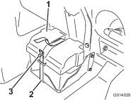
Warning
Incorrect battery cable routing could damage the sprayer and cables, causing sparks. Sparks can cause the battery gasses to explode, resulting in personal injury.
-
Always disconnect the negative (black) battery cable before disconnecting the positive (red) cable.
-
Always connect the positive (red) battery cable before connecting the negative (black) cable.
Warning
Battery terminals or metal tools could short against metal sprayer components causing sparks. Sparks can cause the battery gasses to explode, resulting in personal injury.
-
When removing or installing the battery, do not allow the battery terminals to touch any metal parts of the sprayer.
-
Do not allow metal tools to short between the battery terminals and metal parts of the sprayer.
-
Always keep the battery strap in place to protect and secure the battery.
-
-
Disconnect the positive (red) cable from the battery post.
-
Remove the battery.
Installing the Battery
-
Set the battery on the battery box so that the battery posts are away from the sprayer.
-
Connect the positive (red) cable to the positive (+) battery post and the negative (black) cable to the negative (–) battery post using the bolts and nuts.
-
Slide the insulator boot over the positive battery post.
-
Install the battery cover and secure it with the strap that you removed previously (Figure 94).
Important: Always keep the battery retainer in place to protect and secure the battery.
Charging the Battery
Important: Always keep the battery fully charged. This is especially important to prevent battery damage when the temperature is below 32°F (0°C).
-
Remove the battery from the chassis; refer to Removing the Battery.
-
Connect a 3 to 4 A battery charger to the battery posts and charge the battery at a rate of 3 to 4 A for 4 to 8 hours (12 V).
Important: Do not overcharge the battery.
-
Install the battery in the chassis; refer to Installing the Battery.
Storing the Battery
If you are storing the machine for more than 30 days, remove the battery and charge it fully. Either store it on a shelf or on the machine. Disconnect the battery cables if the battery is stored on the machine. Store the battery in a cool atmosphere to avoid quick deterioration of the charge in the battery. To prevent the battery from freezing, ensure that it is fully charged.
Drive System Maintenance
Inspecting the Wheels/Tires
| Maintenance Service Interval | Maintenance Procedure |
|---|---|
| After the first 8 hours |
|
| After the first 200 hours |
|
| Every 100 hours |
|
| Every 400 hours |
|
Torque the lug nuts at the front wheels to 75 to 102 N∙m (55 to 75 ft-lb) and the lug nuts at the rear wheels to 95 to 122 N∙m (75 to 90 ft-lb).
Operating accidents such as hitting curbs can damage a tire or rim and disrupt wheel alignment, so inspect tire condition after an accident.
Planetary-Gear-Drive Lubricant Specification
SAE 85W-140 gear lubricant
Checking the Planetary-Gear-Drive Lubricant
| Maintenance Service Interval | Maintenance Procedure |
|---|---|
| Every 400 hours |
|
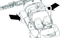
-
With the machine on a level surface, position a wheel so that the fill plug is at the highest (12 o’clock) position and the drain plug is at the lowest (6 o'clock) position (Figure 96).
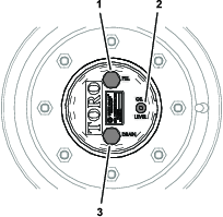
-
Remove the check plug (Figure 53).
You should see the lubricant level at the bottom of the threads in the check-plug hole.
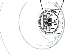
-
Check the O-rings of the check plug for the damage.
If the O-ring is damaged, replace it.
-
If the lubricant level is low, remove the fill plug and add the specified lubricant until it begins to flow out of the check-plug hole (Figure 98); refer to Planetary-Gear-Drive Lubricant Specification.
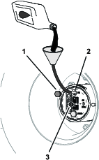
-
Check the O-rings of the fill plug for the damage.
If the O-ring is damaged, replace it.
-
Install the fill plug and the check plug (Figure 98).
-
Repeat steps 1 through 6 for the planetary-gear drive at the other side of the machine.
Changing the Planetary-Gear-Drive Lubricant
| Maintenance Service Interval | Maintenance Procedure |
|---|---|
| After the first 50 hours |
|
| Every 800 hours |
|
Draining the Planetary-Gear-Drive Lubricant
-
With the machine on a level surface, position a wheel so that the fill plug is at the highest (12 o’clock) position and the drain plug is at the lowest (6 o'clock) position; refer to Figure 96 in Checking the Planetary-Gear-Drive Lubricant.
-
Place a drain pan under the hub of the planetary-gear drive, remove the drain plug, fill plug, and the check plug, and allow the lubricant to drain completely (Figure 99).
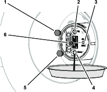
-
Examine the drain and fill plugs for metal shavings.
If fill drain and fill plugs are covered with metal shavings, repair the planetary-gear drive.
-
Check the O-rings of the drain plug, fill plug, and the check plug for the damage.
If the O-ring(s) is damaged, replace it.
-
Install the drain plug.
-
Place a drain pan under the brake housing, remove the drain plug, and allow the lubricant to drain completely (Figure 100).
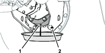
-
Install the drain plug in the brake housing.
Planetary-Gear-Drive with Lubricant Quantity
0.62 L (21 fl oz); refer to Planetary-Gear-Drive Lubricant Specification
Filling the Planetary-Gear-Drive with Lubricant
-
Through the fill-plug hole, slowly add the specified gear lubricant; refer to Figure 98 in Checking the Planetary-Gear-Drive Lubricant.
You should see the lubricant level at the bottom of the threads in the check-plug hole.
Important: If the planetary-gear drive fills before the specified lubricant quantity is added, wait 1 hour or install the plugs, and move the machine approximately 3 m (10 feet) to distribute the lubricant through the brake system. Then, remove the plugs and add the remaining lubricant.
-
Allow the lubricant level to settle for 10 minutes, check the lubricant level, and add lubricant as needed to raise the level to the bottom of the threads in the check-plug hole.
-
Install the fill plug and check plug; refer to Figure 98 in Checking the Planetary-Gear-Drive Lubricant.
-
Repeat the steps in Draining the Planetary-Gear-Drive Lubricant and Filling the Planetary-Gear-Drive with Lubricant for the planetary-gear drive at the other side of the machine.
Adjusting the Front Wheel Toe-In
| Maintenance Service Interval | Maintenance Procedure |
|---|---|
| Every 200 hours |
|
You should measure 0 to 3 mm (0 to 1/8 inch) between the front centerline of the tires and the back centerline of the tires.
-
Check and fill all tires; refer to Checking the Tire Air Pressure.
-
Measure the distance between of the front tires at the axle height at the front and rear of the front tires (Figure 101).
Note: The distance between the front of the tires should be 0 to 3 mm (0 to 1/8 inch) less than the distance between the back side of the front tires.

-
If the measurement does not fall within the specified range, loosen the jam nuts at both ends of the tie rod (Figure 102).
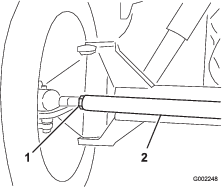
-
Rotate the tie rod to move the front of the tire inward or outward.
-
Tighten the tie rod jam nuts when the adjustment is correct.
-
Ensure that the steering wheel rotates an equal amount in both directions.
Cooling System Maintenance
Cooling System Safety
-
Swallowing engine coolant can cause poisoning; keep out of reach from children and pets.
-
Discharge of hot, pressurized coolant or touching a hot radiator and surrounding parts can cause severe burns.
-
Always allow the engine to cool at least 15 minutes before removing the radiator cap.
-
Use a rag when opening the radiator cap, and open the cap slowly to allow steam to escape.
-
-
Do not operate the machine without the covers in place.
-
Keep your fingers, hands, and clothing clear of the rotating fan and drive belt.
Coolant Specification
The coolant reservoir is filled at the factory with a 50/50 solution of water and ethylene glycol base extended-life coolant. Check the coolant level before you first start the engine and daily thereafter; refer to Checking the Coolant Level.
The following commercially available coolants or a manufacturer-specified equivalent meeting the long-life coolant specification:
|
Ford (Motorcraft™) |
WSS-M97B44-D |
|
FCA—Chrysler (Mopar™) |
MS-12106 |
|
General Motors (AC Delco™) |
GM6277M (Dex-Cool™) |
|
GMW 3420 |
|
|
Volkswagen |
G12 |
|
G12+ |
|
|
G12++ |
|
|
Coolants meeting technical standards ASTM D3306 or D4985, or SAE J1034, J814, or 1941. |
|
|
Important: Do not rely on the color of the coolant to identify the difference between conventional (IAT) and extended-life (OAT) coolant types.Coolant manufacturers may dye extended-life coolant (OAT) in one of the following colors: red, pink, orange, yellow, blue, teal, violet, and green. |
|
|
Ethylene-Glycol Coolant Type |
Corrosion Inhibitor Type |
Service Interval |
|
Extended-life antifreeze |
Organic-acid technology (OAT) |
5-years |
|
Conventional antifreeze (green) |
Inorganic-acid technology (IAT) |
2-years |
Note: When adding coolant to the machine, you will not damage the cooling system by mixing conventional (IAT) antifreeze with extended-life (OAT) antifreeze. However, mixing antifreeze types degrades the long life/extended life attribute of the OAT formulation.
Important: The service interval of conventional (IAT) and extended-life (OAT) blended-coolant mixture—at any ratio—lasts as long as the coolant with the shortest service interval: 2 years.
Checking the Coolant Level
| Maintenance Service Interval | Maintenance Procedure |
|---|---|
| Before each use or daily |
|
Caution
If the engine has been running, the coolant may be hot and pressurized. If you open the radiator cap when the coolant is hot, it could spray out and severely burn you or bystanders.
Allow the engine to cool for at least 15 minutes before opening the radiator cap.
Important: Do not add coolant to an overheated engine until the engine has fully cooled. Adding coolant to an overheated engine may crack the engine block.
-
Position the sprayer on a level surface.
-
Engage the parking brake, shut off the spray pump, shut off the engine, and remove the key.
-
Carefully remove the radiator cap and the expansion-tank cap (Figure 103).
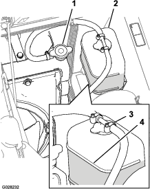
-
Check the coolant level in the radiator and in the expansion tank.
Note: The radiator should be filled to the top of the filler neck and the expansion tank filled to the Full mark on the tank (Figure 103).
-
If the coolant level is low, remove the expansion-tank cap and the radiator cap, and fill the expansion tank to the Full mark and the radiator to the top of the filler neck (Figure 103).
Important: Do not overfill the expansion tank.
Important: Do not use water only or an alcohol/methanol-based coolant.
-
Install the radiator cap and the expansion-tank cap (Figure 103).
Coolant Quantity
5.5 L (5.8 US qt); refer to Coolant Specification
Changing the Coolant
| Maintenance Service Interval | Maintenance Procedure |
|---|---|
| Every 400 hours |
|
Owner provided equipment: a handheld coolant thermometer
-
Position the sprayer on a level surface, engage the parking brake, shut off the spray pump, shut off the engine, and remove the key.
-
Wait until the engine is cool, then remove the radiator cap (Figure 103).
-
Place a large drain pan under the radiator.
-
Open the drain valve and drain the coolant into the pan (Figure 104).
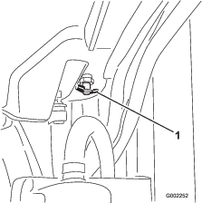
-
Close the drain valve (Figure 104).
-
Remove the radiator cap (Figure 103).
-
Slowly fill the radiator with coolant to approximately 2.5 cm (1 inch) below the sealing surface of the cap.
Note: Use enough coolant to fill the engine and the system lines. This allows the coolant to expand without it overflowing while the engine is warming up.
-
Start the engine with the cap loose on the radiator (Figure 103).
-
Allow the engine to warm up until the thermostat opens.
Note: The engine thermostat should open when the hand-held thermometer indicates the coolant temperature is between 79° to 88°C (175° to 190°F).
-
Once the coolant has warmed up, top off the coolant level to the sealing surface of the cap and tighten the cap (Figure 103).
-
Open the expansion-tank cap and fill the tank with coolant to the Cold level (Figure 103).
-
Check the coolant levels after several engine startup and shut-down cycles.
Note: Add coolant to the radiator and expansion tank as needed.
Brake Maintenance
Adjusting the Brakes
If the brake pedal travels more than 2.5 cm (1 inch) before you feel resistance, adjust the brakes as follows:
-
Position the sprayer on a level surface, shut off the spray pump, shut off the engine, and remove the key.
-
Engage the parking brake.
-
Put blocks under the wheels to prevent the machine from rolling.
-
Release the parking brake.
-
Loosen the front jam nuts on the brake cables under the front end of the sprayer (Figure 105).
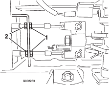
-
Tighten the rear jam nuts equally until the brake pedal moves between 1 to 2 cm (1/2 to 1 inch) before you feel resistance (Figure 105).
Important: Ensure that you tighten both rear nuts equally so that the threaded ends of the brake cables in front of the front nuts are the same length.
-
Tighten the front jam nuts.
Belt Maintenance
Servicing the Alternator Belt
| Maintenance Service Interval | Maintenance Procedure |
|---|---|
| After the first 8 hours |
|
| Every 100 hours |
|
Check the condition and tension of the alternator/cooling fan belt. Replace the belt as necessary.
-
Position the sprayer on a level surface, engage the parking brake, shut off the spray pump, shut off the engine, and remove the key.
-
Check the alternator-belt tension by depressing the belt midway between the alternator and the crankshaft pulleys with 10 kg (22 lb) of force.
Note: The belt should deflect 10 to 12 mm (0.39 to 0.47 inches). If the belt deflection is too much, go to step 3. If the belt tension is correct, you may skip the remainder of this procedure and resume operating the sprayer.
-
Loosen the bolt at the pivot point of the alternator; loosen the bolt that secures the alternator to the slotted brace (Figure 106).
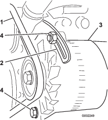
-
Insert a pry bar between the alternator and the engine and carefully pry on the alternator outward.
-
When you achieve the proper tension, tighten the alternator and the bolts to secure the adjustment.
-
Tighten the locknut to secure the adjustment.
Hydraulic System Maintenance
Hydraulic System Safety
-
Seek immediate medical attention if fluid is injected into skin. Injected fluid must be surgically removed within a few hours by a doctor.
-
Safely relieve all pressure in the hydraulic system before performing any work on it.
-
Ensure that all hydraulic-fluid hoses and lines are in good condition and all hydraulic connections and fittings are tight before applying pressure to the hydraulic system.
-
Keep your body and hands away from pinhole leaks or nozzles that eject high-pressure hydraulic fluid.
-
Use cardboard or paper to find hydraulic leaks.
Hydraulic Fluid Specifications
The reservoir is filled at the factory with high-quality hydraulic fluid. Check the level of the hydraulic fluid before you first start the engine and daily thereafter; refer to Checking the Hydraulic Fluid.
Recommended hydraulic fluid: Toro PX Extended Life Hydraulic Fluid; available in 19 L (5 US gallon) pails or 208 L (55 US gallon) drums.
Note: A machine using the recommended replacement fluid requires less frequent fluid and filter changes.
Alternative hydraulic fluids: If Toro PX Extended Life Hydraulic Fluid is not available, you may use another conventional, petroleum-based hydraulic fluid having specifications that fall within the listed range for all the following material properties and that it meets industry standards. Do not use synthetic fluid. Consult with your lubricant distributor to identify a satisfactory product.
Note: Toro does not assume responsibility for damage caused by improper substitutions, so use products only from reputable manufacturers who will stand behind their recommendation.
| Material Properties: | ||
| Viscosity, ASTM D445 | cSt @ 40°C (104°F) 44 to 48 | |
| Viscosity Index ASTM D2270 | 140 or higher | |
| Pour Point, ASTM D97 | -37°C to -45°C (-34°F to -49°F) | |
| Industry Specifications: | Eaton Vickers 694 (I-286-S, M-2950-S/35VQ25 or M-2952-S) | |
Note: Many hydraulic fluids are almost colorless, making it difficult to spot leaks. A red dye additive for the hydraulic fluid is available in 20 ml (0.67 fl oz) bottles. A bottle is sufficient for 15 to 22 L (4 to 6 US gallons) of hydraulic fluid. Order Part No. 44-2500 from your authorized Toro distributor.
Important: Toro Premium Synthetic Biodegradable Hydraulic Fluid is the only synthetic biodegradable fluid approved by Toro. This fluid is compatible with the elastomers used in Toro hydraulic systems and is suitable for a wide-range of temperature conditions. This fluid is compatible with conventional mineral oils, but for maximum biodegradability and performance, the hydraulic system should be thoroughly flushed of conventional fluid. The oil is available in 19 L (5 US gallon) pails or 208 L (55 US gallon) drums from your authorized Toro distributor.
Checking the Hydraulic Fluid
| Maintenance Service Interval | Maintenance Procedure |
|---|---|
| Before each use or daily |
|
Important: If the fluid becomes contaminated, contact an authorized Toro distributor to have the system flushed.Contaminated fluid looks milky or black when compared to clean fluid.
-
Position the sprayer on a level surface, engage the parking brake, shut off the spray pump, shut off the engine, and remove the key.
-
Clean the area around the hydraulic-fluid-tank dipstick cap and remove it (Figure 107).
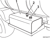
Important: Be very careful not to get dirt or other contaminants into the opening when checking the fluid.
-
Wipe the dipstick clean with a cloth and replace it completely in the tank.
-
Remove the dipstick from the filler neck and check the fluid level (Figure 108).
Note: The fluid level should be at the lower mark on the dipstick when the fluid is cold.
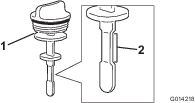
-
If the fluid is low, fill the tank with the specified hydraulic fluid to raise the level to the lower mark; refer to Hydraulic Fluid Specifications.
-
Install the dipstick cap into the tank and secure.
Replacing the Hydraulic Filters
| Maintenance Service Interval | Maintenance Procedure |
|---|---|
| Every 800 hours |
|
| Every 1,000 hours |
|
Warning
Hot hydraulic fluid can cause severe burns.
Allow the hydraulic fluid to cool before performing any maintenance to the hydraulic system.
Important: You may void the warranty on some components if you use any other filter.
Use the Toro replacement filter (See your Parts Manual for the correct part number.)
-
Position the sprayer on a level surface, engage the parking brake, shut off the spray pump, shut off the engine, and remove the key.
-
Locate the 2 hydraulic filters on the machine (Figure 109 and Figure 110).
Note: 1 filter is below the hydraulic-fluid tank and the other filter is located at the rear of the machine on the frame.
-
Forward filter—below the hydraulic tank.
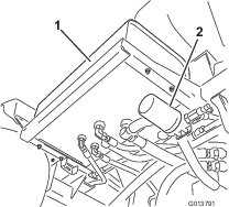
-
Rear filter—located on the machine frame.
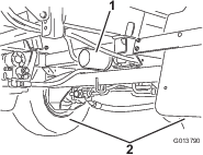
-
-
Clean the area around the filter-mounting area.
-
Place a drain pan under the filter.
-
Remove the filter.
Dispose of the used filter at a certified recycling center.
-
Lubricate the new filter gasket with clean hydraulic fluid; refer to Hydraulic Fluid Specifications.
-
Wipe clean the filter-mounting area with a rag.
-
Thread the filter on until the gasket contacts the mounting plate, then tighten the filter an additional 1/2 turn.
-
Start the engine, set the throttle at fast idle, and let the engine run 3 to 5 minutes to purge air from the hydraulic system.
-
Shut off the engine, check the hydraulic-fluid level, and check for leaks; refer to Checking the Hydraulic Fluid.
Hydraulic-Fluid Quantity
54 L (14.3 US gallons); refer to Hydraulic Fluid Specifications
Changing the Hydraulic Fluid
| Maintenance Service Interval | Maintenance Procedure |
|---|---|
| Every 800 hours |
|
| Every 2,000 hours |
|
Warning
Hot hydraulic fluid can cause severe burns.
Allow the hydraulic fluid to cool before performing any maintenance to the hydraulic system.
Important: You may void the warranty on some components if you use any other fluid.
-
Replace the hydraulic-fluid filters; refer to Replacing the Hydraulic Filters.
-
Clean the area around a hydraulic-hose fitting on the bottom of the hydraulic-fluid tank (Figure 111).

-
Place a large drain pan under the hydraulic tank fittings.
-
Remove the hose fitting from the tank, allowing the fluid to drain into the pan (Figure 111).
Dispose of the used fluid at a certified recycling center.
-
Install the hose and fitting to the tank and tighten it securely.
-
Fill the hydraulic reservoir with approximately 53 L (14 US gallons) of specified hydraulic fluid or equivalent; refer to Hydraulic Fluid Specifications.
-
Start the engine, set the throttle at fast idle, and let the engine run 3 to 5 minutes to purge air from the hydraulic system.
-
Shut off the engine, check the hydraulic-fluid level, and check for leaks; refer to Checking the Hydraulic Fluid.
Sprayer System Maintenance
Inspecting the Hoses
| Maintenance Service Interval | Maintenance Procedure |
|---|---|
| Every 200 hours |
|
| Every 400 hours |
|
Examine each hose in the spray system for cracks, leaks, or other damage. At the same time, inspect the connections and fittings for similar damage. Replace any hoses and fittings if damaged.
Changing the Suction Filter
| Maintenance Service Interval | Maintenance Procedure |
|---|---|
| Every 400 hours |
|
Note: Determine the appropriate suction filter mesh size that you need for your job; refer to Selecting a Suction Filter.
-
Park the machine on a level surface, engage the parking brake, shut off the pump, shut off the engine, and remove the key.
-
At the top of the sprayer tank, remove the retainer that secures the hose fitting attached to the large hose from the filter housing (Figure 112).
-
Remove the hose and hose fitting from the filter housing (Figure 112).
-
Remove the old suction filter from the filter housing in the tank (Figure 113).
Note: Discard the old filter.
-
Install the new suction filter into the filter housing.
Note: Ensure that the filter is fully seated.
-
Align the hose and hose fitting to the filter housing at the top of the tank, and secure the fitting and housing with the retainer that you removed in step 2.
Changing the Pressure Filter
| Maintenance Service Interval | Maintenance Procedure |
|---|---|
| Every 400 hours |
|
-
Move the machine to a level surface, shut off the spray pump, shut off the engine, and remove the key.
-
Align a drain pan under the pressure filter (Figure 114).
-
Rotate the drain plug counterclockwise and remove it from the bowl of the pressure filter (Figure 114).
Note: Allow the bowl to drain completely.
-
Rotate the bowl counterclockwise and remove it from its filter head (Figure 114).
-
Remove the old pressure-filter element (Figure 114).
Note: Discard the old filter.
-
Check the O-ring for the drain plug (located inside the bowl) and the O-ring for the bowl (located inside the filter head) for damage and wear (Figure 114).
Note: Replace any damaged or worn O-rings for the plug, bowl, or both.
-
Install the new pressure-filter element into the filter head (Figure 114).
Note: Ensure that the filter element is firmly seated into the filter head.
-
Install the bowl onto the filter head and tighten by hand (Figure 114).
-
Install the plug into the bowl and tighten by hand (Figure 114).
Changing the Nozzle Filter
Note: Determine the appropriate nozzle filter mesh size that you need for your job; refer to Selecting a Nozzle-Tip Filter (Optional).
-
Park the machine on a level surface, engage the parking brake, shut off the sprayer pump, shut off the engine, and remove the key.
-
Remove the nozzle from the spray turret (Figure 115).
-
Remove the old nozzle filter (Figure 115).
Note: Discard the old filter.
-
Install the new nozzle filter (Figure 115).
Note: Ensure that the filter is fully seated.
-
Install the nozzle onto the spray turret (Figure 115).
Aligning the Cradles to the Outer Booms
-
Engage the parking brake and start the engine, and set the throttle to idle.
-
Slowly raise the left or right outer boom until it is close to the upper cradle tube.
-
Loosen the 2 setscrews that secure the lower cradle tube (Figure 116).
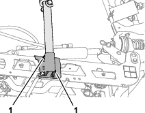
-
Rotate the cradle assemble until the bend in the cradle tube aligns with the slide block on the top tube of the outer boom (Figure 117)
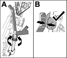
-
Torque the 2 setscrews to 1978 to 2542 N∙cm (175 to 225 in-lb).
-
Lower the outer booms.
-
Slowly raise the other outer boom until it first contacts the cradle.
-
If either upper cradle tube is misaligned with the slide blocks, repeat steps 2 through 7.
Note: The blocks must contact the cradle at the bend in the upper cradle tube (Figure 117).
-
Fully raise the outer booms, shut off the engine, remove the key, and wait for all moving parts to stop.
Adjusting the Booms to Level
The following procedure can be used to adjust the actuators on the center boom to keep the left and right booms at level.
-
Extend the booms to the spray position.
-
Remove the cotter pin from the pivot pin (Figure 118).
-
Lift up on the boom and remove the pin (Figure 118), and slowly lower the boom to the ground.
-
Inspect the pin for any damage, and replace it if necessary.
-
Hold the actuator rod at the flats of the rod using a wrench, then loosen the jam nut (Figure 119).
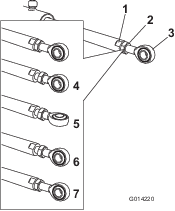
-
Turn the rod end in the actuator rod to shorten or lengthen the extended actuator to the desired position (Figure 119).
Note: You must turn the rod end in half or complete revolutions so that you can assemble the rod to the boom.
-
Tighten the jam nut to secure the actuator and rod end.
-
Raise the boom to align the pivot with the actuator rod.
-
While holding the boom, insert the pin through both boom pivot and rod end (Figure 118).
-
With the pin in place, release the boom and secure the pin with the cotter previously removed.
-
Repeat the procedure for the other actuator rod if necessary.
Inspecting the Nylon Pivot Bushings
| Maintenance Service Interval | Maintenance Procedure |
|---|---|
| Every 400 hours |
|
-
Park the machine on a level surface, engage the parking brake, shut off the pump, shut off the engine, and remove the key.
-
Extend the outer-boom sections to the spray position and support the boom sections using stands or straps and lifting equipment.
-
Remove the bolt and nut that secure the pivot pin, and remove the pin (Figure 120).
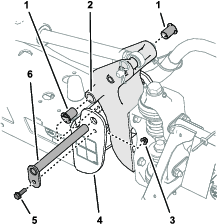
-
Remove the boom and pivot bracket assembly from the end channel of the center frame to access the nylon bushings.
-
Remove and inspect the nylon bushings from the front and back sides of the pivot bracket (Figure 120).
Note: Replace any worn or damaged bushings.
-
Lubricate the nylon bushings with a small amount of oil, and install the bushings into the pivot bracket (Figure 120).
-
Align the holes in the pivot bracket with the holes in the end channel (Figure 120).
-
Install the pivot pin and secure it with the flange bolt and flange locknut removed in step 3.
-
Repeat steps 2 through 8 for the other outer-boom section.
Pump Maintenance
Inspecting the Pump
| Maintenance Service Interval | Maintenance Procedure |
|---|---|
| Every 400 hours |
|
Note: The following machine components are considered parts subject to consumption through use unless found defective and are not covered by the warranty associated with this machine.
Have an authorized Toro distributor check the following internal pump components for damage:
-
Pump diaphragms
-
Pump check valves assemblies
Replace any components, if necessary.
Cleaning
Wash the machine as needed using water alone or with a mild detergent. You may use a rag when washing the machine.
Important: Do not use brackish or reclaimed water to clean the machine.
Note: Do not use power-washing equipment to wash the machine. Power-washing equipment may damage the electrical system, loosen important decals, or wash away necessary grease at friction points. Avoid excessive use of water near the control panel, engine, and battery.
Important: Do not wash the machine with the engine running. Washing the machine with the engine running may result in internal engine damage.
Cleaning the Radiator-Cooling Fins
| Maintenance Service Interval | Maintenance Procedure |
|---|---|
| Every 200 hours |
|
Important: Do not spray water into a hot engine compartment, as it may damage the engine.
-
Position the sprayer on a level surface, engage the parking brake, shut off the spray pump, shut off the engine, and remove the key.
-
Tilt the driver and passenger seats forward and align the prop rod into the detent in the prop-rod-guide slot.
-
Allow the cooling system to cool.
-
Remove the seat-base-access cover; refer to Removing the Seat-Base-Access Panel.
-
Using a soft brush and low-pressure compressed air, clean the fins of the radiator.
Note: Clean the radiator fins more often if needed. Check all coolant hoses and replace any that are worn, leaking, or damaged.
-
Lower the driver and passenger seats.
-
Install the seat-base-access cover; refer to Installing the Seat-Base-Access Panel.
Cleaning the Flow Meter
| Maintenance Service Interval | Maintenance Procedure |
|---|---|
| Every 200 hours |
|
-
Thoroughly rinse and drain the entire spraying system.
-
Remove the flow meter from the sprayer and flush it with clean water.
-
Remove the retainer ring on the upstream side (Figure 121).
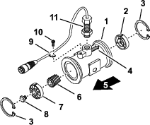
-
Clean the turbine and the turbine hub to remove metal filings and any wettable powders.
-
Inspect the turbine blades for wear.
Note: Hold the turbine in your hand and spin it. It should spin freely with little drag. If it does not, replace it.
-
Assemble the flow meter.
-
Use a low pressure (50 kPa or 5 psi) air jet to ensure that the turbine spins freely.
Note: If the turbine does not spin freely, loosen the hex stud on the bottom of the turbine hub by 1/16 of a turn until it does spins freely.
Cleaning the Agitation and Section Valves
-
To clean the agitation valve; refer to the following sections:
-
To clean the 3 section valves; refer to the following sections:
Removing the Valve Actuator
-
Position the sprayer on a level surface, engage the parking brake, shut off the spray pump, shut off the engine, and remove the key.
-
Remove the retainer that secures the actuator to the manifold valve for the section valve or agitation valve (Figure 122).
Note: Squeeze the 2 legs of the retainer together while pushing it down.
Note: Retain the actuator and retainer for installation in Installing the Valve Actuator.
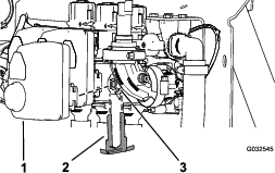
-
Remove the actuator from the manifold valve.
Removing the Agitation-Manifold Valve
-
Remove the quick connect pin that secures the quick-connect coupler for the agitation hose to the manifold for the agitation valve (Figure 123).
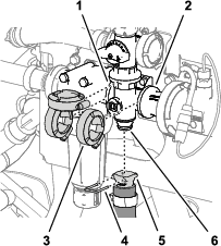
-
Remove the 3 flange clamps that secure the agitation-valve manifold to the flanges of the pressure-filter head and the coupling adapter (Figure 123).
-
Remove the 2 flange-head bolts (1/4 x 3/4 inch) and 2 flange locknuts (1/4 inch) that secure the agitation-valve manifold to the valve support (Figure 124).
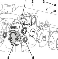
-
Remove the agitation-valve manifold and gaskets from the machine (Figure 124).
Note: If needed, loosen the mounting hardware for the pressure-filter head as needed to provide clearance.
Note: Retain the flange clamps, gaskets, and quick-connect pins for installation in Installing the Agitation-Manifold Valve.
Removing the Section-Manifold Valve
-
Remove the quick-connect pin that secures the quick-connect coupler for the section-bypass valve to the section-manifold valve (Figure 125).
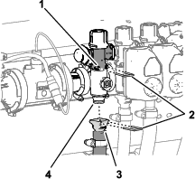
-
Remove the quick connect pin that secures the quick-connect coupler for the section supply hose to the manifold for the quick-connect fitting of the section-manifold valve (Figure 125).
-
Remove the 2 flange clamps that secure the section-manifold valve to the flanges of the adjacent components (Figure 126).
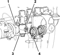
-
For left or right section-valve manifolds, remove the 2 flange-head bolts (1/4 x 3/4 inch) and 2 flange locknuts (1/4 inch) that secure the section-valve manifold to the valve support (Figure 127).
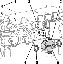
-
Move the section-valve manifold and gaskets down to clear the section-bypass valve and then away from the machine (Figure 127).
Note: If needed, loosen the mounting hardware for the left or right section-valve manifolds as needed to provide clearance.
Note: Retain the flange clamps, gaskets and quick-connect pins for installation in Installing the Section-Manifold Valve.
Cleaning the Manifold Valve
-
Position the valve stem so that it is in the closed position (Figure 128B).
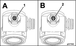
-
Remove the 2 end-cap-fitting assemblies from each end of the manifold body (Figure 129 and Figure 130).
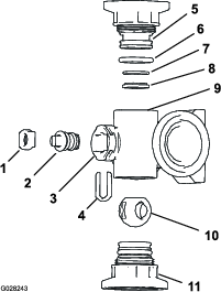
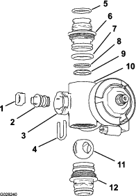
-
Turn the valve stem so that the ball is in the open position (Figure 128A).
Note: When the valve stem is parallel with the valve flow, the ball slides out.
-
Remove the stem retainer from the slots in the stem port in the manifold (Figure 129 and Figure 130).
-
Remove the stem retainer and valve stem seat from the manifold (Figure 129 and Figure 130).
-
Reach into the manifold body and remove the valve-stem assembly (Figure 129 and Figure 130).
-
Clean the inside of the manifold and exterior of the ball valve, valve-stem assembly, stem capture, and end fittings.
Assembling the Manifold Valve
Operator supplied material: Clear silicone grease.
Important: Use only silicone grease when assembling the valve.
-
Check the condition of the outlet fitting O-rings (section valve manifold only), end cap O-rings, back seating O-rings, and ball seat for damage or wear (Figure 129 and Figure 130).
Note: Replace any damaged or worn O-rings or seats.
-
Apply silicone grease to the valve stem and insert it into the valve stem seat (Figure 129 and Figure 130).
-
Install the valve stem and seat into the manifold and secure the stem and seat with the stem retainer (Figure 129 and Figure 130).
-
Ensure that the back seating O-ring and the ball seat are aligned and seated into the end-cap fitting (Figure 129 and Figure 130)
-
Install the end-cap fitting assembly onto the manifold body until the flange of the end-cap fitting touches the manifold body (Figure 129 and Figure 130), then turn the end-cap fitting an additional 1/8 to 1/4 turn.
Note: Use caution so as not to damage the end of the fitting.
-
Insert the ball into the valve body (Figure 131).
Note: The valve stem should fit inside the ball drive slot. If the valve stem does not fit, adjust the position of the ball (Figure 131).
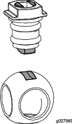
-
Turn the valve stem assembly so that the valve is closed (Figure 128B)
-
Repeat steps 4 and 5 for the other end-cap fitting assembly.
Installing the Section-Manifold Valve
-
Align the 2 gaskets that you removed in Removing the Section-Manifold Valve to the flanges of the section-valve manifold (Figure 132).
Note: If needed, loosen the mounting hardware for the left or right section-valve manifolds as needed to provide clearance.
-
Align the flange of the section-valve manifold between the flanges of the other section-valve (s) and/or coupling adapter (Figure 132).
-
Assemble the quick-connect fitting of the section-valve manifold to the quick-disconnect socket of the section-bypass valve with a quick-connect pin (Figure 132 and Figure 133).
-
Loosely assemble the flange clamps that you removed in Removing the Section-Manifold Valve to the flanges of the section-valve manifold and the flanges of the other section-valve (s) and/or coupling adapter (Figure 134).
-
For left or right section-valve manifolds, assemble the section-valve manifold to the valve support (Figure 132) with the 2 flange-head bolts (1/4 x 3/4 inch) and 2 flange locknuts (1/4 inch) that you removed in Removing the Section-Manifold Valve.
-
Torque the flange-head bolts and flange locknuts to 1978 to 2542 N∙cm (175 to 225 in-lb).
-
Tighten the 2 flange clamps by hand (Figure 134).
-
Assemble the quick-connect coupler of the section hose onto the quick-connect fitting of the section-valve manifold with the quick-connect pin (Figure 133).
-
If you loosened the mounting hardware of the left or right section-valve manifolds, tighten the nut and bolt to 1978 to 2542 N∙cm (175 to 225 in-lb).
Installing the Agitation-Manifold Valve
-
Align the flange of the agitation-valve manifold and 3 gaskets with the flanges of the agitation-bypass valve, pressure filter head, and coupling adapter (Figure 135 and Figure 136).
Note: If needed, loosen the mounting hardware for the pressure-filter head as needed to provide clearance.
-
Loosely secure the agitation-valve manifold to the agitation-bypass valve, pressure filter head, and coupling adapter (Figure 136) with the 3 flange clamps that you removed in Removing the Agitation-Manifold Valve.
-
Assemble the agitation-valve manifold to the valve support with the 2 flange-head bolts (1/4 x 3/4 inch) and 2 flange locknuts (1/4 inch) that you removed in Removing the Agitation-Manifold Valve.
-
Torque the flange-head bolts and flange locknuts to 1978 to 2542 N∙cm (175 to 225 in-lb).
-
Tighten the 3 flange clamps by hand (Figure 136).
-
Assemble the quick-connect coupler of the agitation hose onto the quick-connect fitting of the agitation-valve manifold with the quick-connect pin (Figure 136).
-
If you loosened the mounting hardware for the pressure-filter head, tighten the nut and bolt to 1978 to 2542 N∙cm (175 to 225 in-lb).
Installing the Valve Actuator
-
Align the actuator to the manifold valve (Figure 122).
-
Secure the actuator and valve with the retainer that you removed in step 2 of Removing the Valve Actuator.
Storage
Storage Safety
-
Before you leave the operator’s position, do the following:
-
Park the machine on a level surface.
-
Shut off the spray pump.
-
Engage the parking brake.
-
Shut off the engine and remove the key (if equipped).
-
Wait for all movement to stop.
-
Allow the machine to cool before adjusting, servicing, cleaning, or storing it.
-
-
Do not store the machine or fuel container where there is an open flame, spark, or pilot light, such as on a water heater or other appliance.
Preparing the Machine for Storage
Short-Term Storage
(Less than 30 days)
Perform the procedures that follow:
Cleaning the Exterior of the Machine
Important: Do not use brackish or reclaimed water to clean the machine.
-
Park the machine on a level surface; engage the parking brake; shut off the spray pump and the engine; remove the key; and wait for all movement to stop before leaving the machine.
-
Clean the dirt and grime from the entire machine, including the outside of the cylinder-head fins and blower housing of the engine.
Important: You can wash the machine with mild detergent and water. Do not use high-pressure water to wash the machine. Pressure washing may damage the electrical system or wash away necessary grease at friction points. Avoid excessive use of water, especially near the control panel, lights, engine, and the battery.
Preparing to Condition the Sprayer
-
Move the machine to the drain pad area, engage the parking brake, shut off the spray pump, shut off the engine, remove the key, and wait for all movement to stop before leaving the operator’s position.
-
Drain the fresh-water tank and leave the tank spigot open.
-
Drain the sprayer tank as completely as possible.
-
Prepare rust inhibiting, non-alcohol based, RV antifreeze solution; refer to Preparing the Conditioner.
-
Remove the tube from the back of the pressure gauge and place the end of the tube into a container (Figure 137).
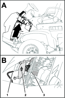
-
Start the engine and lower the outer booms sections.
Conditioning the Sprayer
-
Run the spray pump for a few minutes to circulate the RV antifreeze throughout the spray system and any installed spray accessories.
-
Turn the left, center, and right section switches to the ON position.
-
Turn the master section switch to the ON position and look for the following:
-
Ensure that RV anti-freeze flows from the disconnected end of the pressure-gauge tube.
-
Spray out the nozzle until the RV anti-freeze is visible.
-
-
Turn the master section switch to the OFF position.
-
Turn the pump switch to the OFF position.
-
Use the boom-section lift switches to raise the outer boom sections.
Raise the boom sections until they have moved completely into boom-transport cradle forming the “X” transport position and the lift cylinders are fully retracted.
Note: Make sure that the lift cylinders are fully retracted to prevent actuator rod damage.
-
Shut off the engine.
-
Drain the sprayer tank as completely as possible.
Long-Term Storage
(Longer than 30 days)
Perform the following procedures found in Short-Term Storage:
In addition, perform the procedures that follow:
Servicing the Chassis
-
Check the air pressure in the tires; refer to Checking the Tire Air Pressure.
-
Check the brakes; refer to Adjusting the Brakes.
-
Check and tighten all bolts, nuts, and screws.
Note: Repair or replace any parts that are worn or damaged.
-
Paint all scratched or bare metal surfaces (paint is available from your authorized Toro distributor).
Service the Sprayer
-
Clean the agitation valve and the 3 section valves; refer to Cleaning the Agitation and Section Valves.
-
Grease the sprayer; refer to Greasing the Spray Pump.
-
Check the condition of all spray hoses.
Note: Replace any hoses that are worn or damaged.
-
Tighten all hose clamps and fittings.
Servicing the Engine
-
Service the air cleaner; refer to Checking the Air Cleaner.
-
Change the engine-oil filter and oil; refer toChanging the Engine Oil Filter and Changing the Engine Oil.
Servicing the Fuel System
-
Drain the fuel tank; refer to Draining the Fuel Tank.
-
Prepare fuel with fuel stabilizer according to the manufacturer’s instructions, and add it to the fuel tank.
-
Start the engine and run it at idle speed for 5 minutes.
-
Shut off the engine.
-
Secure all the fuel-system fittings.
Servicing the Battery
-
Move the machine in a clean, dry storage area.
-
Remove the battery from the chassis; refer to Removing the Battery.
Note: Do not connect the battery cables to the battery posts during storage.
-
Check the electrolyte level.
-
Fully charge the battery; refer to Charging the Battery.
Important: The battery must be fully charged to prevent it from freezing and being damaged at temperatures below 32°F (0°C). A fully charged battery maintains its charge for about 50 days at temperatures lower than 4°C (40°F). If the temperatures will be above 4°C (40°F), check the water level in the battery and charge it every 30 days.
Protecting the Machine
-
Remove the key from the starter switch and put the key in a safe place out of the reach of children.
-
Cover the machine to protect it and keep it clean.
Preparing the Machine for Service
-
Insert the pressure-gauge tube into the tube coupler at back of the pressure gauge (Figure 138).
-
Close the spigot of the fresh-water tank.
-
Add fuel to the fuel tank.
-
Fully charge the battery; refer to Charging the Battery.
-
Install the battery into the chassis; refer to Installing the Battery.
Troubleshooting
| Problem | Possible Cause | Corrective Action |
|---|---|---|
| The starter does not rotate the engine. |
|
|
| The engine cranks but does not start. |
|
|
| The engine starts but does not keep running. |
|
|
| The engine runs but knocks or misses. |
|
|
| The engine does not idle. |
|
|
| The engine overheats. |
|
|
| The engine loses power. |
|
|
| There is abnormal vibration or noise. |
|
|
| The machine does not operate or is sluggish in either direction because the engine bogs down or stalls. |
|
|
| The machine does not operate in either direction. |
|
|
| Problem | Possible Cause | Corrective Action |
|---|---|---|
| A spray section does not spray. |
|
|
| A spray section does not turn off. |
|
|
| A spray section valve is leaking. |
|
|
| The pressure drops when you turn on a spray section. |
|
|
| The spray nozzle(s) drip when the section switch(es) is shut off |
|
|
| The sprayer pressure drops while spraying. |
|
|
Schematics
Sprayer System Schematic