| Maintenance Service Interval | Maintenance Procedure |
|---|---|
| Before each use or daily |
|
Introduction
This utility vehicle is intended to be primarily used off-highway to transport people and material loads.
Read this information carefully to learn how to operate and maintain your product properly and to avoid injury and product damage. You are responsible for operating the product properly and safely.
You may contact Toro directly at www.Toro.com for product safety and operation training materials, accessory information, help finding a dealer, or to register your product.
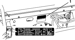
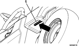
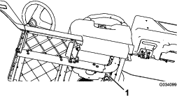
Whenever you need service, genuine Toro parts, or additional information, contact an Authorized Service Distributor or Toro Customer Service and have the model and serial numbers of your product ready. Figure 1 identifies the location of the model and serial numbers on the product. Write the numbers in the space provided.
Important: With your mobile device, you can scan the QR code on the serial number decal (if equipped) to access warranty, parts, and other product information.
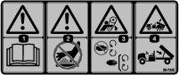
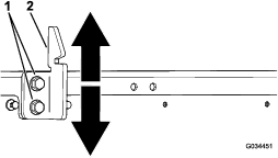
This manual identifies potential hazards and has safety messages identified by the safety-alert symbol (Figure 2), which signals a hazard that may cause serious injury or death if you do not follow the recommended precautions.

This manual uses 2 words to highlight information. Important calls attention to special mechanical information and Note emphasizes general information worthy of special attention.
This product complies with all relevant European directives; for details, please see the separate product specific Declaration of Conformity (DOC) sheet.
It is a violation of California Public Resource Code Section 4442 or 4443 to use or operate the engine on any forest-covered, brush-covered, or grass-covered land unless the engine is equipped with a spark arrester, as defined in Section 4442, maintained in effective working order or the engine is constructed, equipped, and maintained for the prevention of fire.
The enclosed engine owner's manual is supplied for information regarding the US Environmental Protection Agency (EPA) and the California Emission Control Regulation of emission systems, maintenance, and warranty. Replacements may be ordered through the engine manufacturer.
Warning
CALIFORNIA
Proposition 65 Warning
The engine exhaust from this product contains chemicals known to the State of California to cause cancer, birth defects, or other reproductive harm.
Battery posts, terminals, and related accessories contain lead and lead compounds, chemicals known to the State of California to cause cancer and reproductive harm. Wash hands after handling.
Safety
This machine has been designed in accordance with the requirements of SAE J2258.
General Safety
This product is capable of causing personal injury. Always follow all safety instructions to avoid serious personal injury.
Using this product for purposes other than its intended use could prove dangerous to you and bystanders.
-
Read and understand the contents of this Operator’s Manual before you start the engine. Ensure that everyone using this product knows how to use it and understands the warnings.
-
Use your full attention while operating the machine. Do not engage in any activity that causes distractions; otherwise, injury or property damage may occur.
-
Do not put your hands or feet near moving components of the machine.
-
Do not operate the machine without all guards and other safety protective devices in place and working on the machine.
-
Keep the machine a safe distance away from bystanders while it is moving.
-
Keep children out of the operating area. Never allow children to operate the machine.
-
Stop the machine, shut off the engine, and remove the key before servicing or fueling.
Improperly using or maintaining this machine can result in injury. To reduce the potential for injury, comply with these safety instructions and always pay attention to the safety-alert symbol, which means Caution, Warning, or Danger—personal safety instruction. Failure to comply with these instructions may result in personal injury or death.
You can find additional safety information where needed throughout this manual.
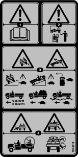
Safety and Instructional Decals
 |
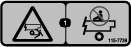
Safety decals and instructions are easily visible to the operator and are located near any area of potential danger. Replace any decal that is damaged or missing. |


Setup
Note: Determine the left and right sides of the machine from the normal operating position.
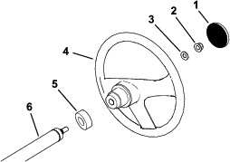
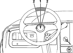
Installing the Steering Wheel (International Models Only)
Parts needed for this procedure:
| Steering wheel | 1 |
| Steering wheel cover | 1 |
| Washer (1/2 inch) | 1 |
| Dust cover | 1 |
-
If the cover is installed, remove it from the hub of the steering wheel (Figure 3).
-
Remove the locknut (1/2 inch) from the steering shaft (Figure 3).
-
Slide the steering wheel, dust cover, and washer (1/2 inch) onto the steering shaft (Figure 3).
Note: With the front wheels straight, orient the steering wheel so that the smaller spoke on the steering wheel is vertical.
-
Secure the steering wheel to the shaft with the locknut (1/2 inch) and tighten it to 18 to 30 N∙m (13 to 22 ft-lb).
-
Install the cover on the steering wheel (Figure 3).
Checking the Fluid Levels and Tire Pressure
-
Check the engine-oil level before and after you first start the engine; refer to Checking the Engine-Oil Level.
-
Check the brake-fluid level before you first start the engine; refer to Checking the Brake-Fluid Level.
-
Check the transaxle-fluid level before you first start the engine; refer to Checking the Transaxle-Fluid Level.
-
Check the air pressure in the tires; refer to Checking the Tire Pressure.
Burnishing the Brakes
To ensure optimum performance of the brake system, burnish (break-in) the brakes before use.
-
Bring the machine up to full speed, apply the brakes to rapidly stop the machine without locking up the tires.
-
Repeat this procedure 10 times, waiting 1 minute between stops, to avoid overheating the brakes.
Important: This procedure is most effective if the machine is loaded with 227 kg (500 lb).
Reading the Manual and Viewing the Setup Material
Parts needed for this procedure:
| Operator's Manual | 1 |
| Engine owner's manual | 1 |
| Registration card | 1 |
| Predelivery Inspection Form | 1 |
| Certificate of Quality | 1 |
| Key | 2 |
-
Read the Operator's Manual and the engine owners's manual.
-
Fill out the registration card.
-
Complete the Predelivery Inspection Form.
-
Review the Certificate of Quality.
Product Overview
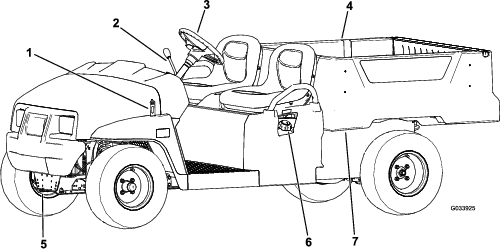
Become familiar with all the controls before you start the engine and operate the machine.
Note: Determine the left and right sides of the machine from the normal operating position.
Control Panel
Accelerator Pedal
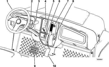
Use the accelerator pedal (Figure 6) to vary the ground speed of the machine. Pressing down the accelerator pedal starts the engine. Pressing the pedal farther increases the ground speed. Releasing the pedal slows the machine, and the engine shuts off.
Note: The maximum forward speed is 26 km/h (16 mph).
Brake Pedal
Use the brake pedal to stop or slow the machine (Figure 6).
Caution
Operating a machine with worn or incorrectly adjusted brakes can may result in personal injury.
If the brake pedal travels to within 25 mm (1 inch) of the machine floor board, adjust or repair the brakes.
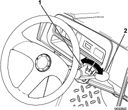
Key Switch
The key switch is located at the lower, right corner of the dash panel (Figure 6).
The key switch has 3 positions: OFF, ON, and START.
There are 2 modes of starting the machine; refer to Starting the Engine.
Parking-Brake Lever
The parking-brake lever is located on the control panel (Figure 6).
Whenever you shut off the engine, engage the parking brake to prevent the machine from accidentally moving. If the machine is parked on a steep grade, ensure that you engage the parking brake.
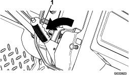
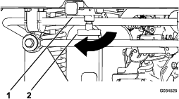
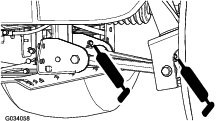
To engage the parking brake, pull the parking-brake lever toward you (Figure 7).
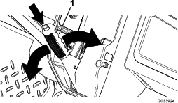
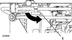
To disengage the parking brake, push down the button on top of the parking-brake lever, pull the parking-brake lever toward you to release pressure, and then push the parking-brake lever forward (Figure 8).
Choke Control
The choke control is located on the control panel. Use the choke to help start a cold engine by pulling the choke control outward (Figure 6). After the engine starts, adjust the choke to keep the engine running smoothly. As the engine warms up, push in the choke control to the OFF position.
Gear-Shift Lever and Gear-Shift Indicator
The gear-shift lever can be set to 3 positions on the gear-shift indicator: FORWARD, REVERSE, and NEUTRAL (Figure 9).
Note: The engine starts and runs in any of the 3 positions.
From the NEUTRAL position, you can move the gear-shift lever left to the FORWARD position or right to the REVERSE position (Figure 9).
Important: Always stop the machine before changing gears.
Horn Button
International Models Only
The horn button is located on the control panel (Figure 6). Press the horn button to sound the horn.
Light Switch
The light switch is located to the left of the steering column (Figure 10). Use the light switch to illuminate the headlights. Push the light switch up to turn on the headlights. Push the light switch down to turn off the lights.
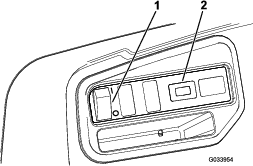
Hour Meter
The hour meter is located to the right of the light switch (Figure 10). Use the hour meter to find out the total number of engine hours. The hour meter starts to function whenever you turn the key switch to the ON position, START position, or if the engine is running.
Note: When the machine is running, the hour meter blinks continuously, recording usage.
USB Power Point
The USB power point is located to the left of the parking-brake lever (Figure 6). Use the power point to power mobile devices.
Important: When you are not using the USB power point, insert the rubber plug to prevent damage to the power point.
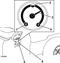
Fuel Gauge
The fuel gauge (Figure 11) is located on the fuel tank in the filler cap, at the left side of the machine. The gauge displays the amount of fuel in the tank.
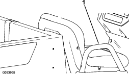
Passenger Handholds
The passenger handholds are located on the outside of each seat (Figure 12).
Note: Specifications and design are subject to change without notice.
| Base weight | 397 kg (875 lb) |
| Rated capacity (on level ground) | 544 kg (1,200 lb) total, including 90.7 kg (200 lb) operator and 91 kg (200 lb) passenger, load, accessories, and attachments |
| Maximum gross vehicle weight (GVW)—on level ground | 941 kg (2,075 lb) total, including all of the weights listed above |
| Maximum cargo capacity (on level ground) | 363 kg (800 lb) total, including rear-mounted accessories |
| Maximum rear cargo-bed-accessory mount capacity | 45 kg (100 lb) total |
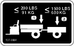
| Tow capacity | Tongue weight: 91 kg (200 lb) |
| Maximum trailer weight: 680 kg (1,500 lb) | |
| Overall width | 119 cm (47 inches) |
| Overall length | 302 cm (119 inches) |
| Overall height | 127.5 cm (50.2 inches) |
| Ground clearance | 21.6 cm (8.5 inches) at the front with no load or operator |
| 14 cm (5.5 inches) at the rear with no load or operator | |
| Wheel base | 220 cm (86.6 inches) |
| Wheel tread (center line to center line) | Front: 119 cm (47 inches) |
| Rear: 119 cm (47 inches) | |
| Cargo bed length | Inside: 102 cm (40 inches) |
| Outside: 114.3 cm (45 inches) | |
| Cargo bed width | Inside: 98 cm (38.5 inches) |
| Outside of the molded fenders: 107.3 cm (42.25 inches) | |
| Cargo bed height | 28 cm (11 inches) inside |
| Engine speed | Low idle: 1,250 to 1,350 rpm |
| High idle: 3,650 to 3,750 rpm |
Attachments/Accessories
A selection of Toro approved attachments and accessories is available for use with the machine to enhance and expand its capabilities. Contact your Authorized Service Dealer or authorized Toro distributor or go to www.Toro.com for a list of all approved attachments and accessories.
To ensure optimum performance and continued safety certification of the machine, use only genuine Toro replacement parts and accessories. Replacement parts and accessories made by other manufacturers could be dangerous, and such use could void the product warranty.
Operation
Note: Determine the left and right sides of the machine from the normal operating position.
Before Operation
Before Operation Safety
General Safety
-
Never allow children or untrained people to operate or service the machine. Local regulations may restrict the age of the operator. The owner is responsible for training all operators and mechanics.
-
Become familiar with the safe operation of the equipment, operator controls, and safety signs.
-
Know how to stop the machine and shut off the engine quickly.
-
Ensure that you and your passengers do not exceed the number of handholds equipped on the machine.
-
Check that all safety devices and decals are in place. Repair or replace all safety devices and replace all illegible or missing decals. Do not operate the machine unless they are present and functioning properly.
Fuel Safety
-
Use extreme care in handling fuel. It is flammable and its vapors are explosive.
-
Extinguish all cigarettes, cigars, pipes, and other sources of ignition.
-
Use only an approved fuel container.
-
Do not remove the fuel cap or fill the fuel tank while the engine is running or hot.
-
Do not add or drain fuel in an enclosed space.
-
Do not store the machine or fuel container where there is an open flame, spark, or pilot light, such as on a water heater or other appliance.
-
If you spill fuel, do not attempt to start the engine; avoid creating any source of ignition until the fuel vapors have dissipated.
Performing Daily Maintenance
Before starting the machine each day, perform the Each Use/Daily procedures listed in .
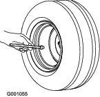
Checking the Tire Pressure
Front and rear tires air pressure specification: 165 to 207 kPa (24 to 30 psi)
Important: Do not exceed the maximum air pressure indicated on the sidewall of the tire.
Note: The air pressure needed in the tires is determined by the payload that you intend to carry.
-
Check the air pressure in the tires.
-
Use lower air pressure in the tires for lighter payloads, for less soil compaction, for a smoother ride, and to minimize tire marks on the ground.
-
Use higher air pressure in the tires for carrying heavier payloads at higher speeds.
-
-
If necessary, adjust the air pressure in the tires by adding or removing air in the tires.
Adding Fuel
Recommended Fuel
-
For best results, use only clean, fresh (less than 30 days old), unleaded gasoline with a cetane rating of 87 or higher ((R+M)/2 rating method).
-
Ethanol: Gasoline with up to 10% ethanol (gasohol) or 15% MTBE (methyl tertiary butyl ether) by volume is acceptable. Ethanol and MTBE are not the same. Gasoline with 15% ethanol (E15) by volume is not approved for use. Never use gasoline that contains more than 10% ethanol by volume, such as E15 (contains 15% ethanol), E20 (contains 20% ethanol), or E85 (contains up to 85% ethanol). Using unapproved gasoline may cause performance problems and/or engine damage which may not be covered under warranty.
-
Do not use gasoline containing methanol.
-
Do not store fuel either in the fuel tank or fuel containers over the winter unless a fuel stabilizer is used.
-
Do not add oil to gasoline.
Filling the Fuel Tank
The fuel-tank capacity is approximately 18.9 L (5 US gallons).
-
Park the machine on a level surface.
-
Engage the parking brake.
-
Shut off the engine and remove the key.
-
Clean the area around the fuel-tank cap (Figure 14).
-
Remove the fuel-tank cap.
-
Fill the tank to about 25 mm (1 inch) below the top of tank (bottom of the filler neck).
Note: This space in the tank allows fuel to expand. Do not overfill the fuel tank.
-
Install the fuel-tank cap securely.
-
Wipe up any spilled fuel.
Breaking in a New Machine
| Maintenance Service Interval | Maintenance Procedure |
|---|---|
| After the first 100 hours |
|
Perform the following guidelines to provide proper performance for the machine.
-
Ensure that the brakes are burnished; refer to Burnishing the Brakes.
-
Check the fluid and engine-oil levels regularly. Remain alert for signs that the machine or its components are overheating.
-
After starting a cold engine, let it warm up for about 15 seconds before using the machine.
Note: Allow more time for the engine to warm up when operating in cold temperatures.
-
Vary the machine speed during operation. Avoid fast starts and quick stops.
-
A break-in oil for the engine is not required. Original engine oil is the same type specified for regular oil changes.
-
Refer to for any special, low-hour checks.
-
Check the front suspension positioning and adjust it, if necessary; refer to Adjusting the Front Wheel Alignment.
During Operation
During Operation Safety
General Safety
-
The owner/operator can prevent and is responsible for accidents that may cause personal injury or property damage.
-
Passengers should sit in the designated seating positions only. Do not carry passengers in the cargo bed. Keep bystanders and pets away from the machine during operation.
-
Wear appropriate clothing, including eye protection; long pants; substantial, slip-resistant footwear; and hearing protection. Tie back long hair and do not wear loose jewelry.
-
Do not operate the machine while ill, tired, or under the influence of alcohol or drugs.
-
Operate the machine outdoors or in a well-ventilated area only.
-
Do not exceed the maximum gross vehicle weight (GVW) of the machine.
-
Use extra caution when operating the machine with a heavy load in the cargo bed. The heavier the load, the more difficult it is to turn or stop.
-
Carrying oversized loads in the cargo bed reduces the stability of the machine.
-
Carrying material that cannot be bound to the machine, such as a large tank of liquid, adversely affects the steering, braking, and stability of the machine.
-
Before you start the engine, ensure that the transmission is in neutral, the parking brake is engaged, and you are in the operating position.
-
You and your passengers should remain seated whenever the machine is moving. Keep your hands on the steering wheel; your passengers should use the handholds provided. Keep your arms and legs within the machine body at all times.
-
Operate the machine only in good visibility. Watch for holes, ruts, bumps, rocks, or other hidden objects. Uneven terrain could overturn the machine. Tall grass can hide obstacles. Use care when approaching blind corners, shrubs, trees, or other objects that may obscure your vision.
-
Always watch out for and avoid low overhangs such as tree limbs, door jambs, overhead walkways, etc.
-
Look behind and down before reversing the machine to be sure of a clear path.
-
Do not drive the machine near drop-offs, ditches, or embankments. The machine could suddenly roll over if a wheel goes over the edge or if the edge gives way.
-
When using the machine on public roads, follow all traffic regulations and use any additional accessories that may be required by law, such as lights, turn signals, slow-moving vehicle (SMV) signs, and others as required.
-
If the machine ever vibrates abnormally, stop the machine immediately, shut off the engine, remove the key, wait for all movement to stop, and inspect for damage. Repair all damage to the machine before resuming operation.
-
Carry a reduced load and reduce the ground speed of the machine when operating on rough, uneven terrain, and near curbs, holes, and other sudden changes in terrain. Loads may shift, causing the machine to become unstable.
-
It can take longer to stop the machine on wet surfaces than on dry surfaces. To dry out wet brakes, drive slowly on level ground while putting light pressure on the brake pedal.
-
Sudden changes in terrain may move the steering wheel unexpectedly, which could result in hand and arm injuries. Reduce your speed and grip the steering wheel loosely around the perimeter, keeping your thumbs out of the way of the steering wheel spokes.
-
Reduce the speed when you operate the machine with the cargo bed removed. Operating the machine at high speed and then quickly stopping may cause the rear wheels to lock up, which impairs your control of the machine.
-
Do not touch the engine, transmission, muffler, or muffler manifold while the engine is running, or soon after you shut off the engine, because these areas may be hot enough to cause burns.
-
Do not leave a running machine unattended.
-
Before leaving the operating position, do the following:
-
Park the machine on level ground.
-
Engage the parking brake.
-
Lower the cargo bed.
-
Shut off the engine and remove the key.
-
-
Do not operate the machine when there is the risk of lightning.
-
Use accessories and attachments approved by The Toro® Company only.
Multi-Passenger Safety
-
You must account for the extra passengers contributing to the overall gross vehicle weight (GVW) of the machine.
-
If you have a load in the cargo bed, ensure that you do not exceed the capacity of the machine by having too many passengers.
-
Passengers should sit in the designated seating positions only. Do not allow passengers to sit in the cargo bed.
-
You and your passengers should remain seated whenever the machine is in motion.
-
The additional machine length results in a larger turn radius, so allow more space to maneuver the machine.
Slope Safety
Note: A 2-post Rollover Protection System (ROPS) is available for this machine as an accessory. Use a ROPS if you will work next to drop-offs, near water, in rough terrain, or on a slope, which could result in a rollover. Contact an authorized Toro distributor for more information.
Slopes are a major factor related to loss-of-control and tip-over accidents, which can result in severe injury or death.
-
Survey the site to determine which slopes are safe for operating the machine and establish your own procedures and rules for operating on those slopes. Always use common sense and good judgment when performing this survey.
-
If you feel uneasy operating the machine on a slope, do not do it.
-
Keep all movement on slopes slow and gradual. Do not suddenly change the speed or direction of the machine.
-
Avoid operating the machine on wet terrain. Tires may lose traction. A rollover can occur before the tires lose traction.
-
Travel straight up and down a slope.
-
If you begin to lose momentum while climbing a slope, gradually engage the brakes and slowly reverse the machine straight down the slope.
-
Turning while going up or down a slope can be dangerous. If you must turn on a slope, do it slowly and cautiously.
-
Heavy loads affect stability on a slope. Carry a reduced load and reduce your ground speed when operating on a slope or if the load has a high center of gravity. Secure the load to the cargo bed of the machine to prevent the load from shifting. Take extra care when hauling loads that shift easily (e.g., liquids, rock, sand, etc.).
-
Avoid starting, stopping, or turning the machine on a slope, especially with a load. Stopping while going down a slope takes longer than stopping on level ground. If you must stop the machine, avoid sudden speed changes, which can cause the machine to tip or roll over. Do not engage the brakes suddenly when rolling rearward, as this may cause the machine to overturn.
Loading and Dumping Safety
-
Do not exceed the gross vehicle weight (GVW) of the machine when operating it with a load in the cargo bed and/or towing a trailer; refer to Specifications.
-
Distribute the load in the cargo bed evenly to improve the stability and control of the machine.
-
Before dumping, ensure that there is no one behind the machine.
-
Do not dump a loaded cargo bed while the machine is sideways on a slope. The change in weight distribution may cause the machine to overturn.
Operating the Cargo Bed
Raising the Cargo Bed to the Dump Position
Warning
A raised bed could fall and injure persons that are working beneath it.
-
Always use the prop rod to hold the bed up before working under the bed.
-
Remove any load material from the bed before raising it.
Warning
Driving the machine with the cargo bed raised could cause the machine to tip or roll easier. You could damage the structure of the cargo bed if you operate the machine with the bed raised.
-
Operate the machine when the cargo bed is down.
-
After emptying the cargo bed, lower it.
Caution
If a load is concentrated near the back of the cargo bed when you release the latches, the bed may unexpectedly tip open, injuring you or bystanders.
-
Center loads in the cargo bed, if possible.
-
Hold the cargo bed down and ensure that no one is leaning over the bed or standing behind it when releasing the latches.
-
Remove all cargo from the bed before lifting the bed up to service the machine.
Raising the Cargo Bed to the Service Position
Lowering the Cargo Bed
Warning
The weight of the bed may be heavy. Hands or other body parts could be crushed.
Keep your hands and other body parts away when lowering the bed.
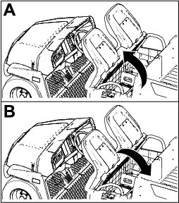
Opening the Tailgate
Closing the Tailgate
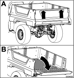
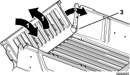
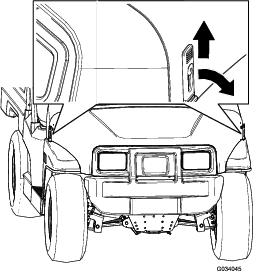
If you unloaded loose material such as sand, landscaping rock, or wood chips from the cargo bed of the machine, some of the material that you unloaded may have lodged in the hinge area of the tailgate. Perform the following steps before closing the tailgate.
-
Use your hands to remove as much of the material from the hinge area as possible.
-
Rotate the tailgate to approximately the 45° position (Figure 18).
-
Use a short, shaking motion to rotate the tailgate back and forth several times (Figure 18).
Note: This action helps move material away from the hinge area.
-
Lower the tailgate and check for material remaining in the hinge area.
-
Repeat steps 1 through 4 until the material is removed from the hinge area.
-
Rotate the tailgate up and lift the tailgate into the notches in the cargo bed.
Using the Rear Cargo Bed Accessory Mount
Use the rear cargo bed accessory mount to attach accessories to the rear of the machine.
Capacity: 45 kg (100 lb)
-
Loosen the “T” handle by rotating it clockwise (Figure 19).
-
Insert your accessory into the receiver until the holes align (Figure 19).
-
Secure the assembled accessory to the receiver tube using the clevis pin and hairpin cotter supplied with the accessory.
-
Tighten the “T” handle by rotating it counterclockwise (Figure 20).
Loading the Cargo Bed
Use the following guidelines when loading the cargo bed and operating the machine:
-
Observe the weight capacity of the machine and limit the weight of the load that you carry in the cargo bed as described in Specifications and on the gross vehicle weight tag of the machine.
Note: The load rating is specified for machine operation on a level surface only.
-
Reduce the weight of the load that you carry in the cargo bed when operating the machine on hills and rough terrain.
-
Reduce the weight of the load that you carry when the materials are tall (and have a high center of gravity), such as a stack of bricks, landscaping timbers, or fertilizer bags. Distribute the load as low as possible to ensure that the load does not reduce your ability to see behind the machine when operating it.
-
Keep loads centered by loading the cargo bed as follows:
-
Evenly position the weight in the cargo bed from side to side.
Important: Tipping over is more likely to occur if the cargo bed is loaded to 1 side.
-
Evenly position the weight in the cargo bed from front to back.
Important: Loss of steering control or the machine may tip over if you position the load behind the rear axle and the traction on the front tires is reduced.
-
-
Use extra caution when transporting oversized loads in the cargo bed, particularly when you cannot center the wight of the oversize load to the cargo bed.
-
Whenever possible, secure the load by binding it to the cargo bed so that it does not shift.
-
When transporting liquid in a large tank (such as a sprayer tank), use caution when driving the machine uphill or downhill, when suddenly changing speed or stopping, or when driving over tough surfaces.
The capacity of the cargo bed is 0.28 m3 (10 ft3). The amount (volume) of material that you can place in the bed without exceeding the load ratings of the machine can vary greatly depending on the density of the material.
Refer to the following table for load volume limits with various materials:
| Material | Density | Maximum Cargo Bed Capacity(on level ground) |
| Gravel, dry | 1522 kg/m3 (95 lb/ft3) | Full |
| Gravel, wet | 1922 kg/m3 (120 lb/ft3) | 3/4 Full |
| Sand, dry | 1442 kg/m3 (90 lb/ft3) | Full |
| Sand, wet | 1922 kg/m3 (120 lb/ft3) | 3/4 Full |
| Wood | 721 kg/m3 (45 lb/ft3) | Full |
| Bark | <721 kg/m3 (<45 lb/ft3) | Full |
| Earth, packed | 1602 kg/m3 (100 lb/ft3) | 3/4 Full (approximately) |
Starting the Engine
-
Sit in the operator seat, insert the key into the key switch, and rotate the key clockwise to the ON or START position.
There are 2 modes of starting the machine:
-
Pedal Start—turn the key switch to the ON position, press down the accelerator pedal, then release your foot from the accelerator pedal.
Note: When you remove your foot from the accelerator pedal, the engine shuts off.
-
Key Start—turn the key switch to the START position and the engine remains on until the is turned to the OFF position.
Note: When using key start mode, you can engage the parking brake and work away from the machine while the engine still runs and the battery holds a charge.
Note: If you turn the key to the START position, the engine cranks until it starts. If the engine cranks for more than 10 seconds, return to the OFF position, and determine the issue (e.g., the choke controls needs to be engaged, check the air cleaner for restrictions, ensure that the fuel tank is full, the spark is bad, etc.) before starting the machine again.
Note: When equipped with the optional backup alarm, if you move the gear-shift selector to the REVERSE position when the key switch is in the ON or START position, a buzzer sounds to warn the operator that the machine is in reverse gear.
-
-
Move the gear-shift selector to the desired direction of travel for the machine.
-
Disengage the parking brake.
-
Slowly step on the accelerator pedal.
Note: If the engine is cold, press and hold the accelerator pedal about half-way down, and pull the choke knob out to the ON position. Return the choke knob to the OFF position after the engine warms up.
Stopping the Machine
Important: When stopping the machine on an incline, use the service brakes to stop the machine and engage the parking brake to hold the machine in place. Using the accelerator to stall the machine on the hill can damage the machine.
-
Remove your foot from the accelerator pedal.
-
Slowly press the brake pedal to apply the service brakes until the machine comes to a complete stop.
Note: The stopping distance may vary depending on the machine load and speed.
Parking the Machine
-
Stop the machine using the service brakes by pressing and holding the brake pedal.
-
Engage the parking brake by pulling the parking-brake lever toward you.
-
Rotate the key counterclockwise to the OFF position.
-
Remove the key.
After Operation
After Operation Safety
General Safety
-
Allow the engine to cool before storing the machine in any enclosure.
-
Do not store the machine or fuel container where there is an open flame, spark, or pilot light, such as on a water heater or other appliance.
-
Keep all parts of the machine in good working condition and all hardware tightened.
-
Replace all worn, damaged, or missing decals.
Transporting the Machine
-
Use care when loading or unloading the machine into a trailer or a truck.
-
Use full-width ramps for loading the machine into a trailer or a truck.
-
Tie the machine down securely.
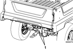
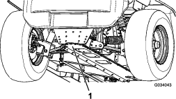
Refer to Figure 21 and Figure 22 for the tie-down locations on the machine.
Note: Load the machine on the trailer with the front of the machine facing forward. If that is not possible, secure the machine hood to the frame with a strap, or remove the hood and transport and secure it separately or the hood may blow off during transport.
Caution
Loose seats may fall off the machine and trailer when transporting the machine, and the seats may land on another machine or obstruct the roadway.
Remove the seats or make sure that the seats are securely fastened to the coupling in the seat shroud.
Towing the Machine
In case of an emergency, you can tow the machine for a short distance; however, this should not be a standard operating procedure.
Warning
Towing at excessive speeds could cause a loss of steering control, resulting in personal injury.
Never tow the machine at faster than 8 km/h (5 mph).
Note: The power steering does not function, making it difficult to steer.
Towing the machine is a 2-person job. If you must move the machine a considerable distance, transport it on a truck or trailer; refer to Towing a Trailer
-
Remove the drive belt from the machine; refer to Replacing the Drive Belt.
-
Affix a tow line to the tongue at the front of the machine’s frame (Figure 21).
-
Move the transmission to the NEUTRAL position and disengage the parking brake.
Towing a Trailer
The machine is capable of pulling trailers. A tow hitch is available for the machine. Contact your authorized Toro distributor for details.
When hauling cargo or towing a trailer, do not overload your machine or trailer. Overloading either the machine or the trailer can cause poor performance or damage to the brakes, axle, engine, transaxle, steering, suspension, body structure, or tires.
Always load a trailer with 60% of the cargo weight in the front of the trailer. This places approximately 10% of the gross trailer weight (GTW) on the tow hitch of the machine.
To provide adequate braking and traction, always load the cargo bed when using a trailer. Do not exceed the GTW or GVW limits.
Avoid parking a machine with a trailer on a hill. If you must park on a hill, engage the parking brake, and chock the tires of the trailer.
Maintenance
Note: Determine the left and right sides of the machine from the normal operating position.
Note: Download a copy of the electrical schematic by visiting www.Toro.com and searching for your machine from the Manuals link on the home page.
Important: Refer to your engine owner’s manual for additional maintenance procedures.
Warning
Failure to properly maintain the machine could result in premature failure of machine systems, causing possible harm to you or bystanders.
Keep the machine well maintained and in good working order as indicated in these instructions.
Caution
Only qualified and authorized personnel should maintain, repair, adjust, or inspect the machine.
-
Avoid fire hazards and have fire-protection equipment present in the work area. Do not use an open flame to check fluid levels or leakage of fuel, battery electrolyte, or coolant.
-
Do not use open pans of fuel or flammable cleaning fluids for cleaning parts.
Caution
If you leave the key in the key switch, someone could accidently start the engine and seriously injure you or other bystanders.
Remove the key from the key switch and disconnect the wires from the spark plugs before you do any maintenance. Set the wires aside so that they do not accidentally contact the spark plugs.
Recommended Maintenance Schedule(s)
| Maintenance Service Interval | Maintenance Procedure |
|---|---|
| After the first 5 hours |
|
| After the first 8 hours |
|
| After the first 50 hours |
|
| After the first 100 hours |
|
| Before each use or daily |
|
| Every 50 hours |
|
| Every 100 hours |
|
| Every 200 hours |
|
| Every 300 hours |
|
| Every 400 hours |
|
| Every 800 hours |
|
| Every 1,000 hours |
|
| Yearly |
|
Maintaining the Machine under Special Operating Conditions
Important: If the machine is subjected to any of the conditions listed below, perform maintenance twice as frequently:
-
Desert operation
-
Cold climate operation—below 10°C (50°F)
-
Trailer towing
-
Frequent operation in dusty conditions
-
Construction work
-
After extended operation in mud, sand, water, or similar dirty conditions, have your brakes inspected and cleaned as soon as possible. This prevents any abrasive material from causing excessive wear.
Pre-Maintenance Procedures
Maintenance Safety
-
Do not allow untrained personnel to service the machine.
-
Before servicing or making any adjustments to the machine, park the machine on a level surface, engage the parking brake, shut off the engine, and remove the key to prevent accidental starting of the machine.
-
Remove any load material from the cargo bed before working underneath it.
-
Always use the prop rod to hold the cargo bed up before working underneath it.
-
Use jack stands to support the machine or components when required.
-
Carefully release pressure from components with stored energy.
-
Do not charge the batteries while servicing the machine.
-
To ensure that the entire machine is in good condition, keep all the nuts, bolts, and screws properly tightened.
-
To reduce the potential fire hazard, keep the engine area free of excessive grease, grass, leaves, and accumulation of dirt.
-
If possible, do not perform maintenance while the engine is running. Keep away from moving parts.
-
If you must run the engine to perform a maintenance adjustment, keep your hands, feet, clothing, and any parts of the body away from the engine and any moving parts. Keep bystanders away from the machine.
-
Clean up oil and fuel spills.
-
Check the parking brake operation frequently. Adjust and service as required.
-
Keep all parts in good working condition and all hardware tightened. Replace all worn or damaged decals.
-
Never interfere with the intended function of a safety device or reduce the protection provided by a safety device. Check their proper operation regularly.
-
Do not overspeed the engine by changing the governor settings. To ensure safety and accuracy, have an authorized Toro distributor to check the maximum engine speed with a tachometer.
-
If major repairs are ever necessary or assistance is required, contact an authorized Toro distributor.
-
To ensure optimum performance and safety, always purchase genuine Toro replacement parts and accessories. Replacement parts and accessories made by other manufacturers could be dangerous. Altering this machine in any manner may affect the operation of the machine, performance, durability, or its use may result in injury or death. Such use could void the product warranty of The Toro® Company.
Preparing the Machine for Maintenance
-
Park the machine on a level surface.
-
Engage the parking brake.
-
Shut off the engine and remove the key.
-
Empty and raise the cargo bed; refer to Raising the Cargo Bed to the Service Position.
Lifting the Machine
Danger
The machine may be unstable when using a jack. The machine could slip off the jack, injuring anyone beneath it.
-
Do not start the machine while the machine is on a jack.
-
Always remove the key from the key switch before getting off the machine.
-
Block the tires when the machine is supported by lifting equipment.
-
Use jack stands to support the machine once you have lifted it.
Important: Whenever you run the machine for routine maintenance and/or diagnostics, ensure that the rear wheels of the machine are 25 mm (1 inch) off the ground, with the rear axle supported on jack stands.
-
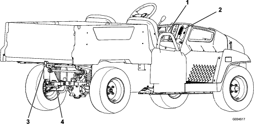
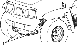
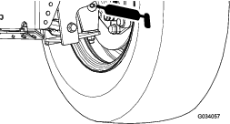
The lifting point at the front of the machine is located at the front of the frame, behind the towing tongue (Figure 23).
-
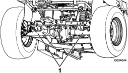
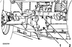
The lifting point at the rear of the machine is located under the axle tubes (Figure 24).
Accessing the Hood
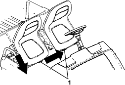
Raising and Lowering the Seat Assembly
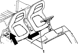
Removing the Seat Assembly
Installing the Seat Assembly
Slide the seat assembly onto the pins and lower the seat assembly (Figure 28).
Lubrication
Greasing the Machine
| Maintenance Service Interval | Maintenance Procedure |
|---|---|
| Every 100 hours |
|
Grease Type: No. 2 lithium grease
-
Use a rag to wipe the grease fitting clean so that foreign matter cannot be forced into the bearing or bushing.
-
With a grease gun, apply 1 or 2 pumps of grease into the grease fittings on the machine.
-
Wipe the excess grease off the machine.
The grease fittings are located at the inner end of the control arms, the tie-rod ball joint, and the outer end of the control arms (Figure 29 and Figure 30).
Greasing the Front Wheel Bearings
| Maintenance Service Interval | Maintenance Procedure |
|---|---|
| Every 300 hours |
|
Grease specification: Mobilgrease XHP™-222
Removing the Hub and Rotor
-
Lift the front of the machine and support it with jack stands.
-
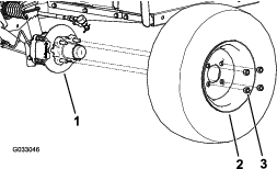
Remove the 4 lug nuts that secure the wheel to the hub (Figure 31).
-
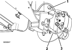
Remove the flange-head bolts (3/8 x 3/4 inch) that secure the bracket for the brake assembly to the spindle and separate the brake from the spindle (Figure 32).
Note: Support the brake assembly before proceeding to the next step.
-
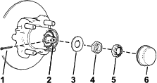
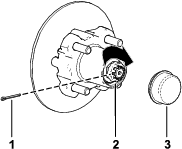
Remove the dust cap from the hub (Figure 33).
-
Remove the cotter pin and nut retainer from the spindle and spindle nut (Figure 33).
-
Remove the spindle nut from the spindle, and separate the hub and rotor assembly from the spindle (Figure 33 and Figure 34).
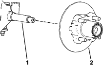
-
Wipe clean the spindle with a rag.
-
Repeat steps 1 through 7 to the hub and rotor at the other side of the machine.
Greasing the Wheel Bearings
-
Remove the outboard bearing and bearing race from the hub (Figure 35).
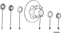
-
Remove the seal, inboard bearing from the hub (Figure 35).
-
Wipe clean the seal and check for wear and damage.
Note: Do not use cleaning solvent to clean the seal. Replace the seal if it is worn or damaged.
-
Clean the bearings and races, and check these parts for wear and damage.
Note: Replace all worn or damaged parts. Ensure that the bearings and races are clean and dry.
-
Clean the cavity of the hub of all grease, dirt, and debris (Figure 35).
-
Pack the bearings with the specified grease.
-
Fill the cavity of hub 50 to 80% full of the specified grease (Figure 35).
-
Assemble the inboard bearing onto the race at the inboard side of the hub and install the seal (Figure 35).
-
Repeat steps 1 through 8 to the bearings for the other hub.
Installing the Hub and Rotor
-
Apply a light coat of the specified grease to the spindle (Figure 36).
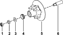
-
Assemble the hub and rotor onto the spindle with the rotor inboard (Figure 36).
-
Assemble the outboard bearing onto the spindle and seat the bearing to the outboard race (Figure 36).
-
Assemble the tab washer onto the spindle (Figure 36).
-
Thread the spindle nut onto the spindle and tighten the nut to 15 N∙m (11 ft-lb), while rotating the hub to seat the bearing (Figure 36).
-
Loosen the spindle nut until the hub rotates freely.
-
Torque the spindle nut to 170 to 225 N∙cm (15 to 20 in-lb).
-
Install the retainer over the nut and check the alignment of the slot in the retainer and the hole in the spindle for the cotter pin (Figure 37).
Note: If the slot in the retainer and the hole in the spindle are not aligned, tighten the spindle nut to align the slot and hole to a maximum torque of 226 N∙cm (20 in-lb) on the nut.
-
Install the cotter pin and bend each legs around the retainer (Figure 37).
-
Install the dust cap onto the hub (Figure 37).
-
Repeat steps 1 through 10 for the hub and rotor at the other side of the machine.
Installing the Brakes and Wheels
-
Clean the 2 flange-head bolts (3/8 x 3/4 inch) and apply a coat of medium-strength thread-locking compound to the threads of the bolts.
-
Align the brake pads to either side of the rotor (Figure 32) and the holes in the caliper bracket with the holes in the brake mount of the spindle frame (Figure 36).
-
Secure the caliper bracket to the spindle frame (Figure 32) using the 2 flange-head bolts (3/8 x 3/4 inch).
Torque the 2 flange-head bolts to 47 to 54 N∙m (35 to 40 ft-lb).
-
Align the holes in the wheel to the studs of the hub and assemble the wheel to the hub with the valve stem outward (Figure 31).
Note: Ensure that the mounting surface of the wheel is flush with the hub.
-
Secure the wheel to the hub using the lug nuts (Figure 31).
Torque the lug nuts to 108 to 122 N∙m (80 to 90 ft-lb).
-
Repeat steps 1 through 5 for the brake and wheel on the other side of the machine.
Engine Maintenance
Engine Safety
-
Shut off the engine, remove the key, and wait for all moving parts to stop before checking the oil or adding oil to the crankcase.
-
Keep your hands, feet, face, clothing, and other body parts away from the muffler and other hot surfaces.
Servicing the Air Cleaner
| Maintenance Service Interval | Maintenance Procedure |
|---|---|
| Every 100 hours |
|
Note: Service the air cleaner more frequently (every few hours) if operating conditions are extremely dusty or sandy.
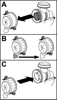
Servicing the Air-Cleaner Cover
| Maintenance Service Interval | Maintenance Procedure |
|---|---|
| Every 50 hours |
|
Check the air-cleaner body for damage which could cause an air leak. Replace a damaged air-cleaner body.
Clean the air-cleaner cover and remove the debris from the dust cap as shown in Figure 38.
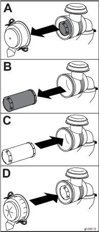
Servicing the Air Filter
| Maintenance Service Interval | Maintenance Procedure |
|---|---|
| Every 100 hours |
|
-
Gently slide the air filter out of the air-cleaner body (Figure 39).
Note: Avoid knocking the air filter into the side of the body.
Important: Do not attempt to clean the air filter.
-
Inspect the new filter for damage by looking into the filter while shining a bright light on the outside of the filter.
Note: Holes in the filter appear as bright spots. Inspect the element for tears, an oily film, or damage to the rubber seal. If the filter is damaged, do not use it.
-
Carefully slide the air filter into the air filter housing.
Important: Do not press on the soft inside area of the filter.
-
Install the air-cleaner cover with the side indicated as “UP” facing upward and secure the latches (Figure 39).
Servicing the Engine Oil
| Maintenance Service Interval | Maintenance Procedure |
|---|---|
| After the first 5 hours |
|
| Every 100 hours |
|
Note: Change the oil more frequently when operating conditions are extremely dusty or sandy.
Note: Dispose of the used engine oil and oil filter at a certified recycling center.
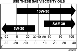
Engine-Oil Specifications
Crankcase Capacity: 1.0 L (1.1 US qt)
Oil Type: API service class SJ or higher detergent oil
Viscosity: See the table below.
Checking the Engine-Oil Level
| Maintenance Service Interval | Maintenance Procedure |
|---|---|
| Before each use or daily |
|
Note: The machine is shipped with oil in the crankcase; however, check the oil before and after you start the engine.
Note: The best time to check the engine oil is when the engine is cool before it has been started for the day. If you have already run the engine, allow the oil to drain back down to the sump for at least 10 minutes before checking. If the oil level is low, add oil to bring the oil level to the Full mark. Do not overfill.
Check the engine-oil level as shown in Figure 41.
Changing the Engine Oil
-
Start the machine and let the engine run for a few minutes.
-
Park the machine on a level surface.
-
Engage the parking brake.
-
Shut off the engine and remove the key.
-
Raise the cargo box and secure it with the prop rod; refer to Raising the Cargo Bed to the Service Position.
-
Change the engine oil as shown in Figure 42.
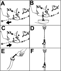
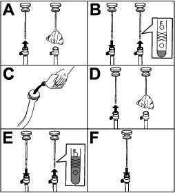
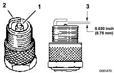
Servicing the Spark Plug
Checking and Replacing the Spark Plug
| Maintenance Service Interval | Maintenance Procedure |
|---|---|
| Every 100 hours |
|
Carburetor Model Spark Plug Type: Champion XC12YC
EFI Model Spark Plug Type: Champion RC12LC4
Air Gap: 0.76 mm (0.03 inch)
Important: You must replace a cracked, fouled, dirty, or malfunctioning spark plug. Do not sand-blast, scrape, or clean electrodes by using a wire brush because grit may eventually release from the plug and fall into the cylinder. The result is usually a damaged engine.
Note: The spark plug usually lasts a long time; however, the plug should be removed and checked whenever the engine malfunctions.
-
Clean the area around the spark plug so that foreign matter cannot fall into the cylinder when you remove the spark plug.
-
Pull the wire off the terminal of the spark plug.
-
Remove the plug from the cylinder head.
-
Check the condition of the side electrode, center electrode, and center electrode insulator to ensure that there is no damage (Figure 43).
Note: Do not use a damaged or worn spark plug. Replace it with a new spark plug of the specified type.
-
Set the air gap between the center and side of the electrodes at 0.76 mm (0.03 inch) as shown in Figure 43.
-
Install the spark plug into the cylinder head, and torque the plug to 27 N∙m (20 ft-lb).
-
Install the spark-plug wire.
-
Repeat steps 1 through 7 for the other spark plug.
Adjusting the High/Low Idle
-
Lift the cargo bed and secure it with the prop rod.
-
At the throttle cable housing, loosen the forward jam nut and tighten the rear jam nut to increase the low idle (Figure 44).
-
Test the high idle with a tachometer:
-
Ensure that the shift lever is in the NEUTRAL position.
-
Start the engine.
-
Fully depress the accelerator pedal and measure the engine speed with a tachometer; the engine speed should be between 3650 to 3750 rpm. If it is not, shut off the engine and adjust the cable jam nuts.
Important: Do not lower the high idle. Test with a tachometer to ensure that the high idle is between 3650 to 3750 rpm.
-
-
Lower and secure the cargo bed.
Fuel System Maintenance
Inspecting Fuel Lines and Connections
| Maintenance Service Interval | Maintenance Procedure |
|---|---|
| Every 400 hours |
|
Inspect the fuel lines, fittings, and clamps for signs of leaking, deterioration, damage, or loose connections.
Note: Repair any damaged or leaking fuel system component before using the machine.
Replacing the Fuel Filter
| Maintenance Service Interval | Maintenance Procedure |
|---|---|
| Every 400 hours |
|
-
Park the machine on a level surface.
-
Engage the parking brake.
-
Shut off the engine and remove the key.
-
Raise the bed and support it with the prop rod.
-
Disconnect the battery; refer to Disconnecting the Battery.
-
Place a clean container under the fuel filter and replace the fuel filter as shown in Figure 45.
-
Connect the battery and lower the cargo bed; refer to Connecting the Battery.
Servicing the Carbon Canister
Checking the Air Filter for the Carbon Canister
| Maintenance Service Interval | Maintenance Procedure |
|---|---|
| After the first 50 hours |
|
| Every 200 hours |
|
Check the opening at the bottom of the air filter for the carbon canister to ensure that it is clean and free of debris and obstructions (Figure 46).
Clean the air filter for the carbon canister with clean, compressed air.
Electrical System Maintenance
Electrical System Safety
Warning
Battery posts, terminals, and related accessories contain lead and lead compounds, chemicals known to the State of California to cause cancer and reproductive harm. Wash hands after handling.
-
Disconnect the battery before repairing the machine. Disconnect the negative terminal first and the positive last. Connect the positive terminal first and the negative last.
-
Charge the battery in an open, well-ventilated area, away from sparks and flames. Unplug the charger before connecting or disconnecting the battery. Wear protective clothing and use insulated tools.
Servicing the Battery
Battery voltage: 12 V with 300 A (cold-cranking) at -18°C (0°F).
-
Always keep the battery clean and fully charged.
-
If the battery terminals are corroded, clean them with a solution of 4 parts water and 1 part baking soda.
-
Apply a light coating of grease to the battery terminals to prevent corrosion.
Disconnecting the Battery
Warning
Incorrect battery cable routing could damage the machine and cables, causing sparks. Sparks can cause the battery gasses to explode, resulting in personal injury.
-
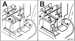
Always disconnect the negative (black) battery cable before disconnecting the positive (red) cable.
-
Always reconnect the positive (red) battery cable before reconnecting the negative (black) cable.
-
Always keep the battery strap in place to protect and secure the battery.
Warning
Battery terminals or metal tools could short against metal machine components, causing sparks. Sparks can cause the battery gasses to explode, resulting in personal injury.
-
When removing or installing the battery, do not allow the battery terminals to touch any metal parts of the machine.
-
Do not allow metal tools to short between the battery terminals and metal parts of the machine.
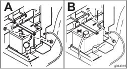
Disconnect the battery as shown in Figure 47.
Removing the Battery
-
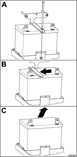
Disconnect the battery cables; refer to Disconnecting the Battery.
-
Remove the battery as shown in Figure 48.
Installing the Battery
-
Install the battery as shown in Figure 49.
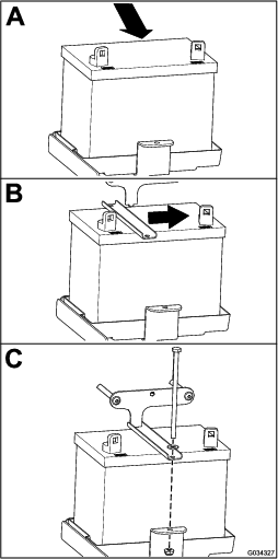
-
Connect the battery cables; refer to Connecting the Battery.
Connecting the Battery
Connect the battery as shown in Figure 50.
Charging the Battery
Warning
Charging the battery produces gasses that can explode.
Never smoke near the battery and keep sparks and flames away from battery.
Important: Always keep the battery fully charged (1.260 specific gravity). This is especially important to prevent battery damage when the temperature is below 0°C (32°F).
-
Remove the battery from the machine; refer to Removing the Battery.
-
Connect a 3 to 4 A battery charger to the battery posts. Charge the battery at a rate of 3 to 4 A for 4 to 8 hours (12 V).
Note: Do not overcharge the battery.
-
Install the battery in the chassis; refer to Installing the Battery.
Storing the Battery
If you store the machine for more than 30 days, remove the battery and charge it fully. Either store it on the shelf or on the machine. Leave the cables disconnected if it is stored on the machine. Store the battery in a cool atmosphere to avoid quick deterioration of the charge in the battery. To prevent the battery from freezing, make sure it is fully charged.
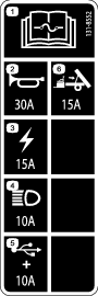
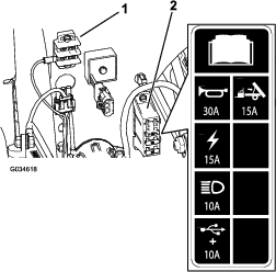
Replacing the Fuses
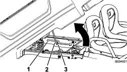
There are 4 fuses in the electrical system. They are located beneath the seat assembly (Figure 51).
Note: If you install the optional lift kit, you will receive another fuse block to install next to the fuse block installed currently.
| Horn | 30 A |
| Main power | 15 A |
| Headlights | 10 A |
| USB power point/options | 10 A |
| Optional lift kit (open—extra fuse block comes with kit) | 15 A |
Maintaining the Headlights
Replacing the Bulbs
Caution
If you install a higher wattage bulb than the system is designed for, you may damage the 12 V power supply, or at a minimum, blow the fuse.
Always use the specified Toro LED bulb to prevent this issue.
Caution
The bulbs become extremely hot when in operation. Handling a hot bulb can cause severe burns and personal injury.
Always allow enough time for the bulbs to cool before replacing them. Use care whenever handling the bulb.
Specification: See your Parts Catalog.
-
Disconnect the batteries; refer to Disconnecting the Battery.
-
Open the hood; refer to Raising the Hood.
-
Disconnect the electrical connector for the harness from the connector of the lamp assembly at the back of the headlight housing (Figure 52).
-
Rotate the lamp assembly 1/4 turn counterclockwise and moving it rearward, out of the headlight housing (Figure 52).
-
Insert the new lamp assembly and headlight housing and align the tabs in the lamp assembly with the slots in the headlight housing (Figure 52).
-
Secure lamp assembly by turning it 1/4 turn clockwise (Figure 52).
-
Connect the electrical connector for the harness to the connector of the new lamp assembly (Figure 52).
-
Connect the batteries and close the hood; refer to Connecting the Battery.
Replacing the Headlight
-
Disconnect the batteries; refer to Disconnecting the Battery.
-
Open the hood; refer to Raising the Hood.
-
Disconnect the electrical connector for the harness from the connector of the lamp assembly (Figure 53).
-
Remove the speed clips that secure the headlight to the headlight bracket (Figure 53).
Note: Retain all parts for installation of the new headlight.
-
Remove the headlight assembly by moving it forward through the opening in the front bumper (Figure 53).
-
Install the new headlight through the opening in the bumper (Figure 53).
Note: Ensure the adjustment posts are lined up with the holes in the mounting bracket behind the bumper.
-
Secure the headlight assembly with the speed clips that you removed in step 4.
-
Connect the electrical connector for the harness to the connector of the lamp assembly (Figure 53).
-
Adjust the headlights to direct the beams to the desired position, refer to Adjusting the Headlights.
Adjusting the Headlights
Use the following procedure to adjust the headlight beam position whenever a headlight assembly is replaced or removed.
-
Turn the key switch to the ON position, and turn on the headlights.
-
At the back of the headlight assembly, rotate adjustment screws (Figure 53) to pivot the headlight assembly and align the position of the cast beam.
-
Connect the battery and close the hood; refer to Connecting the Battery.
Drive System Maintenance
Maintaining the Tires
| Maintenance Service Interval | Maintenance Procedure |
|---|---|
| Every 100 hours |
|
-
Inspect the tires and rims for signs of wear and damage.
Note: Operating accidents, such as hitting curbs, can damage a tire or rim and also disrupt wheel alignment, so inspect tire condition after an accident.
-
Torque the wheel lug nuts to 108 to 122 N∙m (80 to 90 ft-lb).
Inspecting the Steering and Suspension Components
| Maintenance Service Interval | Maintenance Procedure |
|---|---|
| Every 100 hours |
|
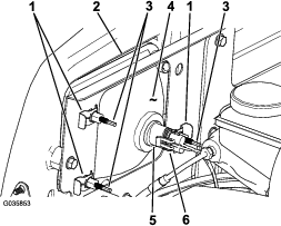
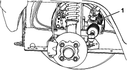
With the steering wheel at the centered position (Figure 54), turn the steering wheel to the left or right. If you turn the steering wheel more than 13 mm (1/2 inch) to the left or right, and the tires do not turn, check the following steering and suspension components to ensure that they are not loose or damaged:
-
Steering shaft to the steering-rack assembly joint
Important: Inspect the condition and security of the pinion-shaft seal (Figure 55).
-
Steering-rack assembly tie rods
Adjusting the Front Wheel Alignment
| Maintenance Service Interval | Maintenance Procedure |
|---|---|
| Every 100 hours |
|
Preparing to Adjust Camber or Toe-in
-
Check the tire pressure to ensure that the front tires are inflated to 82 kPa (12 psi).
-
Either add weight to the driver's seat equal to the average operator who will run the machine, or have an operator sit on the seat. The weight or operator must remain on the seat for the duration of the adjustment procedure.
-
On a level surface, roll the machine straight back 2 to 3 m (6 to 10 ft) and then straight forward to the original starting position. This allows the suspension to settle into the operating position.
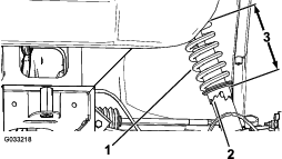
Adjusting the Camber
Owner provided tools: spanner wrench, Toro Part No. 132-5069; refer to your authorized Toro distributor.
Important: Make the camber adjustments only if you are using a front attachment or if there is uneven tire wear.
-
Check the camber alignment at each wheel; the alignment should be as close to neutral (zero) as possible.
Note: The tires should be aligned with the tread evenly on the ground to reduce uneven wear.
-
If the wheel camber is out of alignment, use the spanner wrench to rotate the collar on the shock absorber to align the wheel (Figure 56).
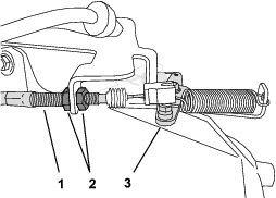
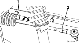
Adjusting the Front Wheel Toe-in
Important: Before adjusting toe-in, ensure that the camber adjustment is as close to neutral as possible; refer to Adjusting the Camber.
-
Measure the distance between both of the front tires at the axle height at both the front and rear of the front tires (Figure 57).

-
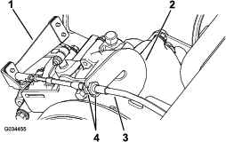
If the measurement does not fall within 0 to 6 mm (0 to 1/4 inch), loosen the jam nuts at the outer end of the tie rods (Figure 58).
-
Rotate both tie rods to move the front of the tire inward or outward.
-
Tighten the tie rod jam nuts when the adjustment is correct.
-
Ensure that there is full travel of the steering wheel in both directions.
Checking the Transaxle-Fluid Level
| Maintenance Service Interval | Maintenance Procedure |
|---|---|
| Every 100 hours |
|
Fluid Type: SAE 80W-90 (API MT-1) or SAE 80W-90 (API GL-5)
-
Park the machine on a level surface.
-
Engage the parking brake.
-
Shut off the engine and remove the key.
-
Remove the fill plug on the transaxle (Figure 59).
Note: The fluid level should be even with the bottom of the fill plug.
-
If the fluid level is low, remove the fill plug and add the specified fluid until it runs out of the hole (Figure 59).
-
Replace the fill plug and torque it to 20 to 27 N∙m (15 to 20 ft-lb).
Changing the Transaxle Fluid
| Maintenance Service Interval | Maintenance Procedure |
|---|---|
| Every 800 hours |
|
Fluid Type: SAE 80W-90 (API MT-1) or SAE 80W-90 (API GL-5)
Fluid Capacity: 1.6 L (1.7 US qt)
-
Align a drain pan under the drain plug (Figure 59).
-
Remove the fill plug and the seal (Figure 59).
Note: Retain the fill plug and seal for installation in step 6.
-
Remove the drain plug and the seal, and allow the fluid to drain completely (Figure 59).
Note: Retain the drain plug and seal for installation in step 4.
-
Install the drain plug and seal, and torque it to 20 to 27 N∙m (15 to 20 ft-lb).
-
Fill the transaxle with the specified fluid until it runs out of the fill hole.
-
Install the fill plug and seal, and torque it to 20 to 27 N∙m (15 to 20 ft-lb).
Checking the Neutral Gear-Shift Position
| Maintenance Service Interval | Maintenance Procedure |
|---|---|
| Before each use or daily |
|
| Every 100 hours |
|
When performing routine maintenance and/or engine diagnostics, the transaxle must be shifted into NEUTRAL. The machine has a NEUTRAL position on the gear-shift selector, which controls the neutral in the transaxle. The following steps should be taken to make sure that the neutral shift lever operates the transaxle neutral correctly:
-
Set the gear-shift selector to the NEUTRAL position.
-
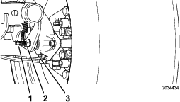
Rotate the secondary clutch (Figure 66) to see if it spins freely in the NEUTRAL position.
-
Set the gear-shift selector to the FORWARD position.
-
Rotate the secondary clutch (Figure 66) to see if it rotates the rear wheels.
-
Set the gear-shift selector to the REVERSE position.
-
Rotate the secondary clutch (Figure 66) to see if it rotates the rear wheels.
-
If any of these tests fail, proceed to Adjusting the Neutral Gear-Shift Position.
Adjusting the Neutral Gear-Shift Position
-
Loosen the jam nuts on the gear-shift cable and adjust them as necessary (Figure 60).
-
Test the gear-shift position by rotating the gear-shift selector to the 3 different positions and check to see if the shift lever (Figure 60) shifts properly when shifting the gears; refer to Gear-Shift Lever and Gear-Shift Indicator.
-
Verify that all of the positions are working correctly by repeating the steps in Checking the Neutral Gear-Shift Position.
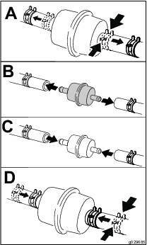
Maintaining the Primary Drive Clutch
| Maintenance Service Interval | Maintenance Procedure |
|---|---|
| Every 400 hours |
|
Caution
The dust in the clutch will become airborne and could damage your eyes or you could inhale it, causing breathing difficulties.
Wear safety goggles and a dust mask or other eye and respiratory protection when performing this procedure.
-
Raise and latch the cargo bed.
-
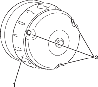
Remove the 3 bolts securing the cover to the clutch, and remove the cover (Figure 61).
Note: Retain the cover and bolts for installation.
-
Thoroughly clean the inside of the cover and the inner components of the clutch using compressed air.
-
Install the clutch cover and secure it with the 3 bolts (Figure 61) that you removed in 2.
-
Lower the cargo bed.
Reducing the Top Speed
Caution
The dust in the clutch will become airborne and could damage your eyes or you could inhale it, causing breathing difficulties.
Wear safety goggles and a dust mask or other eye and respiratory protection when performing this procedure.
-
Raise and latch the cargo bed; refer to Raising the Cargo Bed to the Service Position.
-
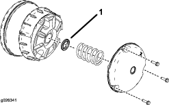
Remove the bolts securing the primary clutch cover as shown in Figure 62.
Important: Use caution when removing the clutch cover; the spring is under compression.
Important: Take note of the X orientation on the clutch covers and clutch assemblies for later installation.
-
Remove the spring.
-
Add or remove spacers to adjust the top speed. Use the following table to determine the amount of spacers needed.
Spacers Top Speed 2 (standard) 16 mph (standard) 3 12 mph 4 9 mph 5 6 mph 6 4 mph Important: Do not operate the machine without at least 2 clutch spacers in place.
-
Install the spring and clutch cover.
Important: Ensure that the X is placed back in the original location.
-
Torque the bolts to 179 to 228 N–m (132 to 168 in-lbs).
Cooling System Maintenance
Cooling System Safety
-
Swallowing engine coolant can cause poisoning; keep out of reach from children and pets.
-
Discharge of hot, pressurized coolant or touching a hot radiator and surrounding parts can cause severe burns.
-
Always allow the engine to cool at least 15 minutes before removing the radiator cap.
-
Use a rag when opening the radiator cap, and open the cap slowly to allow steam to escape.
-
-
Do not operate the machine without the covers in place.
-
Keep your fingers, hands and clothing clear of rotating fan and drive belt.
-
Shut off the engine and remove the key before performing maintenance.
Cleaning the Engine-Cooling Areas
| Maintenance Service Interval | Maintenance Procedure |
|---|---|
| Every 100 hours |
|
Important: Operating the engine with a blocked rotating screen, dirty or plugged cooling fins, or cooling shrouds removed causes engine damage due to overheating.
Important: Never clean the engine with a pressure washer because water could contaminate the fuel system.
Clean the inlet, cooling fins, and external surfaces of the engine.
Note: Clean the engine cooling components more often under extremely dusty and dirty conditions.
Brake Maintenance
Checking the Parking Brake
-
Engage the parking brake by pulling the parking-brake lever toward you, until you feel tension.
-
If you do not feel tension when pulling the parking-brake toward you within 11.4 to 16.5 cm (4-1/2 to 6-1/2 inches) from the “P” symbol on the dash, then you need to adjust the parking brake; refer to Adjusting the Parking Brake.
Adjusting the Parking Brake
-
Ensure that the parking brake is disengaged.
-
Using jack stands, lift the rear of the machine; refer to Lifting the Machine.
-
Using 2 wrenches, hold the adjusting post on the caliper in place with 1 wrench, and loosen the jam nut 1/4 turn with the other wrench (Figure 63).
-
While holding the adjusting post and the jam nut in place, turn the adjusting post in to tighten (Figure 63).
Note: Perform this step until you feel drag on the wheel.
-
While holding the adjusting post and the jam nut in place, back off 1/4 turn (Figure 63).
-
While holding the adjusting post and the jam nut in place, tighten the jam nut (Figure 63).
-
Perform steps 1 through 6 to the other side.
-
Verify that the parking brake is adjusted to the proper tension; refer to Checking the Parking Brake.
Note: If you cannot adjust the parking brake to the required tension, the brake pads may be worn and need to be replace. Contact your Authorized Service Dealer for assistance.
Checking the Brake-Fluid Level
| Maintenance Service Interval | Maintenance Procedure |
|---|---|
| Before each use or daily |
|
Brake Fluid Type: DOT 3
-
Park the machine on a level surface.
-
Engage the parking brake.
-
Shut off the engine and remove the key.
-
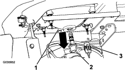
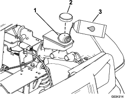
Raise the hood to gain access to the master-brake cylinder and reservoir (Figure 64).
-
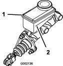
Look at the outline of the fluid level at the side of the reservoir (Figure 65).
Note: The level should be above the Minimum line.
-
If the fluid level is low, perform the following:
-
Close the hood of the machine.
Inspecting the Brakes
| Maintenance Service Interval | Maintenance Procedure |
|---|---|
| Every 100 hours |
|
Brakes are a critical safety component of the machine. As with all safety components, they should be closely inspected at regular intervals to ensure optimum performance and safety. The following inspections should be done every 100 hours:
-
Inspect the brake lining for wear or damage. If the lining (brake pad) thickness is less than 1.6 mm (1/16 inch), you should replace the brake lining.
-
Inspect the backing plate and other components for signs of excessive wear or deformation. If any deformation is found, replace the appropriate components.
-
Check the brake-fluid level; refer to Checking the Brake-Fluid Level.
Replacing the Service and Parking-Brake Pads
| Maintenance Service Interval | Maintenance Procedure |
|---|---|
| Every 400 hours |
|
Contact your Authorized Toro Service Dealer to inspect and possibly replace the service and parking-brake pads.
Changing the Brake Fluid
| Maintenance Service Interval | Maintenance Procedure |
|---|---|
| Every 1,000 hours |
|
Contact your authorized Toro distributor.
Belt Maintenance
Servicing the Drive Belt
Checking the Drive Belt
| Maintenance Service Interval | Maintenance Procedure |
|---|---|
| After the first 8 hours |
|
| Every 200 hours |
|
-
Park the machine on a level surface.
-
Engage the parking brake.
-
Shut off the engine and remove the key.
-
Raise the cargo bed and secure it with the prop rod; refer to Raising the Cargo Bed to the Dump Position.
-
Shift the transmission into NEUTRAL.
-
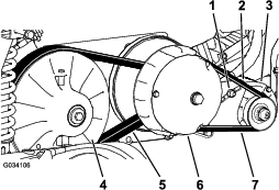
Rotate and inspect the belt (Figure 66) for signs of excessive wear or damage.
Note: Replace the belt if it is excessively worn or damaged; refer to Replacing the Drive Belt.
-
Lower the cargo bed.
Replacing the Drive Belt
-
Raise the cargo bed; refer to Raising the Cargo Bed to the Dump Position.
-
Shift the transmission into the NEUTRAL position, engage the parking brake, rotate the key switch to the OFF position, and remove the key.
-
Rotate and route the belt over the secondary clutch (Figure 66).
-
Remove the belt from the primary clutch (Figure 66).
Note: Discard the old belt.
-
Align the new belt over the primary clutch (Figure 66).
-
Rotate and route the belt over the secondary clutch (Figure 66).
-
Lower the cargo bed.
Adjusting the Starter-Generator Belt
| Maintenance Service Interval | Maintenance Procedure |
|---|---|
| After the first 8 hours |
|
| Every 200 hours |
|
-
Raise the cargo bed; refer to Raising the Cargo Bed to the Dump Position.
-
Loosen the pivot nut for the starter generator (Figure 66).
-
Align a pry bar between the engine mount and starter.
-
Apply downward pressure to the pry bar to rotate the starter down in the slot until the belt tension only allows 6 mm (1/4 inch) belt deflection with 44 N∙m (10 ft-lb) of force (Figure 66).
-
Tighten the pivot nut hand tight, and remove the pry bar (Figure 66).
-
Torque the pivot nut to 88 to 115 N∙m (65 to 85 ft-lb).
-
Lower the cargo bed.
Chassis Maintenance
Adjusting the Cargo-Bed Latches
If the cargo-bed latch is out of adjustment, the cargo bed vibrates up and down as you drive the machine. You can adjust the latch posts to make the latches hold the cargo bed snugly to the chassis.
-
Verify that the cargo bed is latching.
Note: If the cargo bed does not latch, the bed-latch striker is likely too low. If the cargo bed latches, but vibrates up and down as you drive, the bed-latch striker is likely too high.
-
Raise the cargo bed; Raising the Cargo Bed to the Dump Position.
-
Loosen the 2 bolts on the bed-latch striker and move the striker up or down, depending on if the striker is too high or too low (Figure 67).
-
Tighten the 2 bolts on the bed-latch striker (Figure 67).
-
Verify that the adjustment is correct by latching the cargo bed several times.
Cleaning
Washing the Machine
The machine should be washed as needed. Use water alone or with a mild detergent. A rag may be used when washing the machine.
Important: Do not use power washing equipment to wash the machine. Power washing equipment may damage the electrical system, loosen important decals, or wash away necessary grease at friction points. Avoid excessive use of water near the control panel, engine, and battery.
Important: Do not wash the machine with the engine running. Washing the machine with the engine running may result in internal engine damage.
Storage
Storage Safety
-
Let the engine cool before storing the machine.
-
Do not store the machine or fuel near flames or drain the fuel indoors.
Storing the Machine
-
Park the machine on a level surface.
-
Engage the parking brake.
-
Shut off the engine and remove the key.
-
Clean the dirt and grime from the entire machine, including the outside of the cylinder-head fins of the engine and blower housing.
Important: You can wash the machine with mild detergent and water. Do not use power-washing equipment to wash the machine. Pressure washing the machine may damage the electrical system or wash away necessary grease at friction points. Avoid excessive use of water near the control panel, lights, engine, and the battery.
-
Inspect the brakes; refer to Inspecting the Brakes.
-
Service the air cleaner; refer to Servicing the Air Cleaner.
-
Grease the machine; refer to Greasing the Machine.
-
Change the engine oil; refer to Changing the Engine Oil.
-
Check the tire pressure; refer to Checking the Tire Pressure.
-
For storage over 30 days, prepare the fuel system as follows:
-
Add a petroleum based fuel stabilizer/conditioner to fuel in the tank.
Important: Do not store fuel containing stabilizer/conditioner longer than the duration recommended by the fuel-stabilizer manufacturer.
Follow mixing instructions from fuel stabilizer manufacturer—29.5 ml (1 fl oz per gallon).
Important: Do not use an alcohol-based fuel stabilizer (ethanol or methanol).
Note: The use of fuel stabilizer/conditioner is most effective when mixed with fresh gasoline and used at all times.
-
Run the engine to distribute conditioned fuel through the fuel system (5 minutes).
-
Shut off the engine, allow the engine to cool, and drain the fuel tank.
Note: Dispose of fuel properly. Recycle as according to local codes.
-
Start the engine again and run it until it stops.
-
Choke the engine.
-
Start and run the engine until it does not start again.
-
-
Remove the spark plug and check their condition; refer to Servicing the Spark Plug.
-
With the spark plugs removed from the engine, pour 2 tablespoons of engine oil into the spark plug hole.
-
Use the electric starter to crank the engine and distribute the oil inside the cylinder.
-
Install the spark plug(s) and tighten it to recommended torque; refer to Servicing the Spark Plug.
Note: Do not install the wire on the spark plug(s).
-
Remove the battery from the chassis, and charge it fully; refer to Removing the Battery.
Note: Do not connect the battery cables to the battery posts during storage.
Important: The battery must be fully charged to prevent it from freezing and being damaged at temperatures below 0°C (32°F). A fully charged battery maintains its charge for about 50 days at temperatures lower than 4°C (40°F).
-
Check and tighten all bolts, nuts, and screws. Repair or replace any part that is damaged.
-
Paint all scratched or bare metal surfaces.
Note: Paint is available from your Authorized Service Dealer.
-
Store the machine in a clean, dry garage or storage area.
-
Remove the key from the key switch and put it in a safe place out of the reach of children.
-
Cover the machine to protect it and keep it clean.