Safety
Hydraulic System Safety
-
Seek immediate medical attention if fluid is injected into skin. Injected fluid must be surgically removed within a few hours by a doctor.
-
Ensure that all hydraulic-fluid hoses and lines are in good condition and all hydraulic connections and fittings are tight before applying pressure to the hydraulic system.
-
Keep your body and hands away from pinhole leaks or nozzles that eject high-pressure hydraulic fluid.
-
Use cardboard or paper to find hydraulic leaks.
-
Safely relieve all pressure in the hydraulic system before performing any work on the hydraulic system.
Safety and Instructional Decals
 |
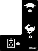
Safety decals and instructions are easily visible to the operator and are located near any area of potential danger. Replace any decal that is damaged or missing. |
Installation
Preparing the Machine

-
Move the machine to a level surface.
-
Engage the parking brake.
-
Lower the loader arms.
-
Shut off the engine and remove the key.
-
Wait for the engine to cool.
-
Unlatch the hood, open it, and support it with the prop rod; refer to Accessing Internal Components in the Operator’s Manual for your machine.
-
Relieve hydraulic pressure; refer to Hydraulic System Maintenance in the Operator’s Manual for your machine.
Disconnecting the Battery
Opening the Battery Disconnect Switch
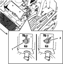
Important: Ensure that the engine is cool before using the battery-disconnect switch.
Turn the battery disconnect switch to the OFF position (Figure 2).
Note: If the machine does not have a battery-disconnect switch, refer to Removing the Negative Battery Cable.
Removing the Negative Battery Cable
Warning
Incorrect battery cable routing could damage the machine and cables causing sparks. Sparks can cause the battery gasses to explode, resulting in personal injury.
-
Always disconnect the negative (black) battery cable before disconnecting the positive (red) cable.
-
Always connect the positive (red) battery cable before connecting the negative (black) cable.
-
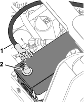
Remove the front screen; refer to Accessing Internal Components in the Operator’s Manual for your machine.
-
Loosen the nut and tee bolt securing the negative battery cable to the battery post (Figure 3), and remove the cable from the battery.
Note: Position the battery cable away from the battery post.
Removing the Cover Plate and Baffle
Determine the left and right sides of the machine from the normal operating position.
-
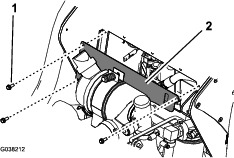
Remove the 3 flange-head capscrews (1/4 x 3/4 inch) securing the cover plate front of the control panel frame, and remove the cover plate (Figure 4).
-
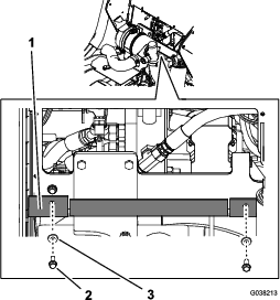
Remove the 3 flange-head capscrews (1/4 x 3/4 inch) and 3 washers (1/4 inch) securing the front of the rubber baffle to the bottom of the control panel frame (Figure 5).
-
Push the rubber baffle down to provide access to the hydraulic hoses.
Separating the Traction Enable Valve
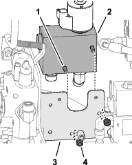
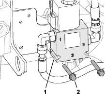
Remove the 2 flange-head capscrews (1/4 x 2 inches) that secure the traction enable valve to the low-flow valve to the bracket (Figure 6).
Note: Retain the flange-head capscrews. Move the valve as needed to provide access.
Removing the Hoses and Tubes
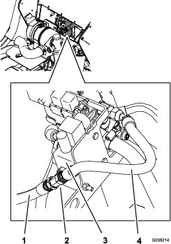
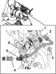
Removing the Auxiliary Valve Hose and Pump Hose
Removing the Auxiliary Valve Tube and Pump Hose
Removing the Right Loader Hoses
-
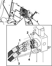
Mark the upper loader hose “Port B”, and remove the hose from the auxiliary valve fitting (Figure 9).
-
Mark the lower loader hose “Port A”, and remove the hose from the auxiliary valve fitting.
Removing the Port T Hose
-
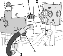
Remove the remaining hose from the port-T fitting in the auxiliary valve and the port-T fitting in the loader-arm valve. (Figure 10).
Note: Discard the hose.
-
Remove the fitting from port-T of the auxiliary valve.
Note: Discard the fitting.
Preparing the Auxiliary Valve
Parts needed for this procedure:
| 45° fitting | 1 |
| 90° fitting | 1 |
-
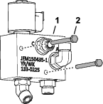
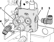
Assemble a 45° fitting into port-T of the auxiliary valve (Figure 11).
Note: Do not tighten the fitting.
-
Assemble a 90° fitting into port-P of the auxiliary valve.
Note: Do not tighten the fitting.
Installing the Low Flow Valve
Parts needed for this procedure:
| Low-flow valve | 1 |
| 90° fitting | 1 |
| 45° fitting | 1 |
| Bolt (1/4 x 2-1/2 inches) | 2 |
| Locknut (1/4 inch) | 2 |
Assembling the Low-Flow Valve Fittings
-
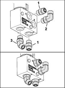
Assemble a 90° fitting into port-A of the low-flow valve (Figure 12).
-
Assemble a 45° fitting into port-T of the low-flow valve.
-
Assemble straight fittings port-C and port-P of the low-flow valve (Figure 12).
-
Align the fitting is 45° and 90° fittings as shown in Figure 12.
-
Torque the fittings to 79 to 98 N∙m (58 to 72 ft-lb).
Assembling the Low-Flow Valve to the Bracket
-
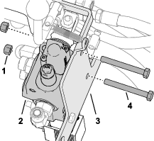
Remove the 2 rear bolts (5/16 x 2-3/4 inches) and 2 locknuts (5/16 inch) securing auxiliary valve to the valve bracket as shown in Figure 17.
-
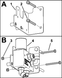
Assemble the bolts (5/16 x 2-3/4 inches) that you removed in step 1 through the holes in the low-flow valve bracket (Figure 14).
-
Install the low-flow valve to the bracket using 2 bolts (1/4 x 2-1/2 inches) and 2 locknuts (1/4 inch).
Assembling the Low-Flow Valve to the Bracket
Installing the Low-Flow Valve to the Auxiliary Valve
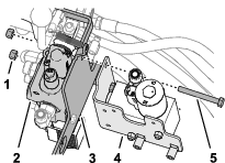
Loosely assemble the low-flow valve bracket to the valve bracket and auxiliary valve with the 2 rear bolts (5/16 x 2-3/4 inches) and locknut (5/16 inch).
Note: Do not tighten the locknuts and bolts.
Installing the Tubes
Parts needed for this procedure:
| 90° fitting | 1 |
| Manifold tube | 1 |
| S-shaped tube | 1 |
| U-shaped tube | 1 |
| L-shaped tube | 1 |
Installing the Manifold Tube and S-Shaped Tube
Note: Do not torque the tube nuts until all tubes are assembled.
-
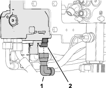
Loosely assemble the 90° fitting onto the straight fitting in the loader-arm valve port-T (Figure 18).
-
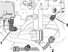
Loosely assemble the manifold tube to the 90° fitting of the loader-arm valve and the 45° fitting (bottom) in port-T of the low-flow valve (Figure 19).
-
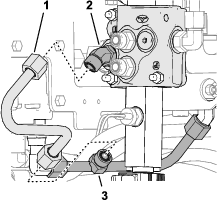
Loosely assemble the S-shaped tube to the fitting in the manifold tube and the 45° fitting in port-T of the auxiliary valve (Figure 20).
-
Torque the 90° fitting of loader-arm valve port-T (Figure 19) and the 45° fitting in auxiliary valve port-T (Figure 20) to 79 to 98 N∙m (58 to 72 ft-lb).
-
Torque the tube nuts of the manifold tube and S-shaped tube to 50 to 64 N∙m (37 to 47 ft-lb).
Installing the U-Shaped Tube
-
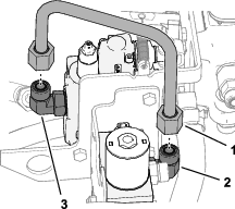
Assemble the U-shaped tube to the 90° fitting in port-P of the auxiliary valve and the 90° in port fitting in Port A in the low-flow valve (Figure 21).
-
Torque the 90° fitting in auxiliary valve port-P to 79 to 98 N∙m (58 to 72 ft-lb).
-
Torque the tube nuts to 50 to 64 N∙m (37 to 47 ft-lb).
Installing the L-Shaped Tube
-
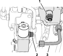
Assemble the L-shaped tube to the straight fitting in port-C of the low-flow valve and the straight fitting in port-T-1 of the loader-arm valve (Figure 22).
-
Torque the tube nuts to 50 to 64 N∙m (37 to 47 ft-lb).
Tightening the Valve Mounting Hardware
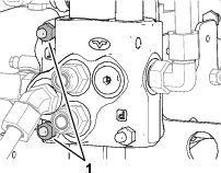
Tighten the 2 bolts and 2 locknuts that secure the low-flow valve bracket to the loader valve and bracket (Figure 23).
Installing the Hoses
Parts needed for this procedure:
| Hose 41.9 cm (16-1/2 inches) | 1 |
| Hose protector | 1 |
| Cable tie | 3 |
Installing the Right Loader Hosed
-
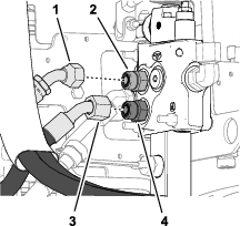
Assemble the upper loader hose marked “Port B” to the upper auxiliary valve fitting (Figure 24).
-
Torque the swivel nut of the hose to 50 to 64 N∙m (37 to 47 ft-lb).
-
Assemble the lower loader hose marked “Port A” to the lower auxiliary valve fitting.
-
Torque the swivel nut of the hose to 50 to 64 N∙m (37 to 47 ft-lb).
Installing the Low-Flow Valve and Pump Hoses
Machine serial numbers 408833816 and later are shown; machine serial numbers 408833815 and before are similar.
-
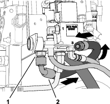
Assemble the 90° fitting of the 41.9 cm (16-1/2 inches) hose to the straight fitting in port-P of the low-flow valve (Figure 25).
-
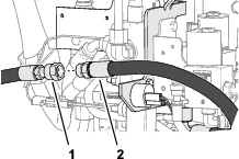
Assemble the straight fitting of the 41.9 cm (16-1/2 inches) hose to the fitting of the hose that you marked “Pump” (Figure 26).
-
Torque the 90° fitting of the 41.9 cm (16-1/2 inches) hose to 50 to 64 N∙m (37 to 47 ft-lb).
-
Torque the straight fittings of the 41.9 cm (16-1/2 inches) hose and the pump hose to 50 to 64 N∙m (37 to 47 ft-lb).
-
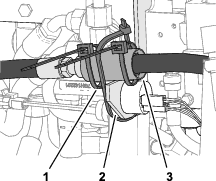
Wrap the straight fittings of the 2 hoses with the hose protector, and secure the protector to the fittings with 2 cable ties (Figure 27).
-
Secure the protector and hoses to the valve bracket as shown in Figure 27.
Installing the Switch and Wire Harness
Parts needed for this procedure:
| Switch | 1 |
| Decal | 1 |
| Wire harness | 1 |
-
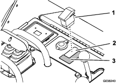
Remove the plug from the console and install the switch (Figure 28).
-
If the decal on the console does not show the rabbit and turtle symbols near the switch, affix the kit decal (Figure 28).
-
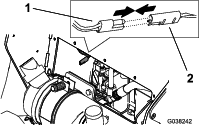
Unplug the cap from the auxiliary connector on the machine wire harness and connect the kit wire harness to the connector (Figure 29).
-
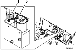
Connect the kit wire harness to the switch and the low-flow valve (Figure 30).
Assembling the Traction Enable Valve
-
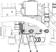
Align the notches in the body of the traction enable valve with the threaded support tubes if the low-flow valve bracket (Figure 31).
-
Secure the traction enable valve to the bracket with the 2 flange-head capscrews (1/4 x 2 inches).
Checking for Hydraulic Leaks
Positioning the Baffle
Move the baffle up over the hoses and components, toward the installation position.
Closing the Battery Disconnect Switch
Turn the battery disconnect switch to the OFF position (Figure 32).
Note: If the machine does not have a battery-disconnect switch, refer to Installing the Negative Battery Cable.

Installing the Negative Battery Cable
-
Install the negative battery cable onto the battery post (Figure 33), and tighten the tee bolt and nut.

-
Install the front screen; refer to Accessing Internal Components in the Operator’s Manual for your machine.
Checking for Leaks
Hydraulic Safety
-
Seek immediate medical attention if fluid is injected into skin. Injected fluid must be surgically removed within a few hours by a doctor.
-
Ensure that all hydraulic-fluid hoses and lines are in good condition and all hydraulic connections and fittings are tight before applying pressure to the hydraulic system.
-
Keep your body and hands away from pinhole leaks or nozzles that eject high-pressure hydraulic fluid.
-
Use cardboard or paper to find hydraulic leaks.
-
Safely relieve all pressure in the hydraulic system before performing any work on the hydraulic system.
-
Start the engine.
-
Check tubes, hoses, and fitting at the loader valve, low-flow valve, and auxiliary valve for hydraulic leaks.
Machine serial numbers 408833816 and late—check the traction enable valve fittings and hose.
Note: Repair any hydraulic leaks.
-
Shut off the engine.
-
Check the hydraulic fluid level; refer to Hydraulic System Maintenance in the OPERATOR’S MANUAL for your machine.
Note: If needed, add hydraulic fluid.
Installing Baffle and Cover Plate
-
Align the holes in the rubber baffle (Figure 34) with the holes in the bottom of the control panel frame.

-
Secure the baffle to the panel with the 3 flange-head capscrews (1/4 x 3/4 inch) and 3 washers (1/4 inch) that you removed in Removing the Cover Plate and Baffle.
-
Align the holes in the cover plate (Figure 35) with the holes in the front of the control panel frame.

-
Secure the cover plate to the panel with the flange-head capscrews (1/4 x 3/4 inch) that you removed in Removing the Cover Plate and Baffle.
-
Close and latch the hood.
