| Maintenance Service Interval | Maintenance Procedure |
|---|---|
| Before each use or daily |
|
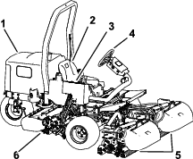
Introduction
This machine is a ride-on, reel-blade lawn mower intended to be used by professional, hired operators in commercial applications. It is primarily designed for cutting grass on well-maintained turf. Using this product for purposes other than its intended use could prove dangerous to you and bystanders.
Read this information carefully to learn how to operate and maintain your product properly and to avoid injury and product damage. You are responsible for operating the product properly and safely.
Visit www.Toro.com for more information, including safety tips, training materials, accessory information, help finding a dealer, or to register your product.
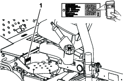
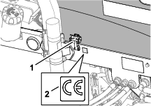
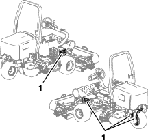
Whenever you need service, genuine Toro parts, or additional information, contact an Authorized Service Dealer or Toro Customer Service and have the model and serial numbers of your product ready. Figure 1 identifies the location of the model and serial numbers on the product. Write the numbers in the space provided.
Important: With your mobile device, you can scan the QR code on the serial number plate (if equipped) to access warranty, parts, and other product information.
This manual identifies potential hazards and has safety messages identified by the safety-alert symbol (Figure 2), which signals a hazard that may cause serious injury or death if you do not follow the recommended precautions.

This manual uses 2 words to highlight information. Important calls attention to special mechanical information and Note emphasizes general information worthy of special attention.
This product complies with all relevant European directives. For details, please see the separate product specific Declaration of Conformity (DOC) sheet.
It is a violation of California Public Resource Code Section 4442 or 4443 to use or operate the engine on any forest-covered, brush-covered, or grass-covered land unless the engine is equipped with a spark arrester, as defined in Section 4442, maintained in effective working order or the engine is constructed, equipped, and maintained for the prevention of fire.
The enclosed engine owner’s manual is supplied for information regarding the US Environmental Protection Agency (EPA) and the California Emission Control Regulation of emission systems, maintenance, and warranty. Replacements may be ordered through the engine manufacturer.
Warning
CALIFORNIA
Proposition 65 Warning
Diesel engine exhaust and some of its constituents are known to the State of California to cause cancer, birth defects, and other reproductive harm.
Battery posts, terminals, and related accessories contain lead and lead compounds, chemicals known to the State of California to cause cancer and reproductive harm. Wash hands after handling.
Use of this product may cause exposure to chemicals known to the State of California to cause cancer, birth defects, or other reproductive harm.
Safety
This machine has been designed in accordance with EN ISO 5395 (when you complete the setup procedures) and ANSI B71.4-2017.
General Safety
This product is capable of amputating hands and feet and of throwing objects.
-
Read and understand the contents of this Operator’s Manual before starting the engine.
-
Use your full attention while operating the machine. Do not engage in any activity that causes distractions; otherwise, injury or property damage may occur.
-
Do not put your hands or feet near moving components of the machine.
-
Do not operate the machine without all guards and other safety protective devices in place and functioning properly on the machine.
-
Keep bystanders and children out of the operating area. Never allow children to operate the machine.
-
Shut off the engine, remove the key, and wait for all movement to stop before you leave the operator’s position. Allow the machine to cool before adjusting, servicing, cleaning, or storing it.
Improperly using or maintaining this machine can result in injury.
To reduce the potential for injury, comply with these safety instructions
and always pay attention to the safety-alert symbol  , which means
Caution, Warning, or Danger—personal safety instruction. Failure
to comply with these instructions may result in personal injury or
death.
, which means
Caution, Warning, or Danger—personal safety instruction. Failure
to comply with these instructions may result in personal injury or
death.
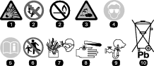
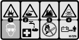
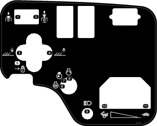
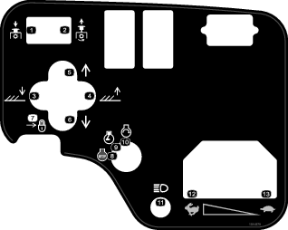
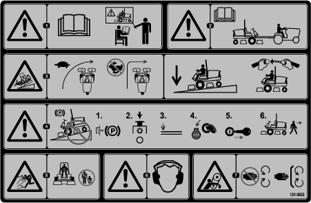
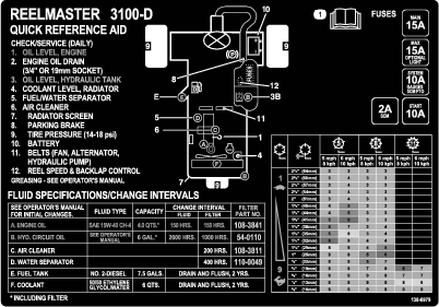
Safety and Instructional Decals
|
Safety decals and instructions are easily visible to the operator and are located near any area of potential danger. Replace any decal that is damaged or missing. |


CE Machines

Model 03170
Model 03171
Setup
Note: Determine the left and right sides of the machine from the normal operating position.
Installing the Wheels
Parts needed for this procedure:
| Front wheel assembly | 2 |
| Rear wheel assembly | 1 |
Important: The rim and tire of the rear wheel is narrower than that of the front 2 rims and tires.
-
Mount a wheel assembly onto the wheel hub with the valve stem aligned outward.
-
Secure the wheel to the hub with the lug nuts, and torque the nuts in a crossing pattern to 61 to 88 N∙m (45 to 65 ft-lb).
-
Repeat steps 1 and 2 for the other wheel assemblies.
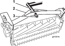
Installing the Steering Wheel
Parts needed for this procedure:
| Steering wheel | 1 |
| Steering-wheel cap | 1 |
| Large washer | 1 |
| Jam nut | 1 |
| Screw | 1 |
-
Slide the steering wheel onto the steering shaft (Figure 3).
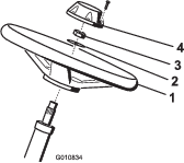
-
Slide the washer onto the steering shaft (Figure 3).
-
Secure the steering wheel to the shaft (Figure 3) with a jam nut and tighten it to 27 to 35 N∙m (20 to 26 ft-lb).
-
Install the cap to the steering wheel and secure it with a screw (Figure 3).
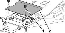
Charging and Connecting the Battery
Danger
Battery electrolyte contains sulfuric acid, which is lethal if consumed and causes severe burns.
-
Do not drink electrolyte and avoid contact with skin, eyes, or clothing. Wear safety glasses and rubber gloves.
-
Fill the battery where clean water is always available for flushing the skin.
-
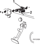
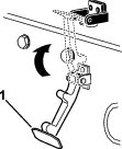
Remove the 2 knobs that secure the battery cover to the machine, and remove the cover (Figure 4).
-
Measure the battery voltage.
Note: If you measure 12.4 V or higher, the battery is charged.
-
If you measure 12.3 V or less, charge the battery at a rate of 3 to 4 A for 4 to 8 hours.
Warning
Charging the battery produces gasses that can explode.
-
Keep sparks and flames away from battery.
-
Never smoke near the battery.
-
-
When the battery is charged, disconnect the charger from the electrical outlet and battery posts.
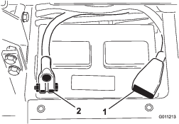
-
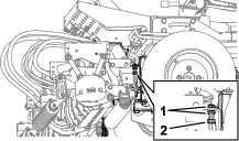
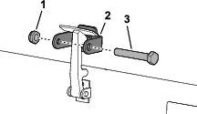
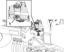
Install the positive cable (red) to the positive (+) battery terminal, and secure them with T-bolt and nut (Figure 5).
Note: Ensure that the positive (+) terminal is all the way onto the post and the cable is positioned snug to the battery.
Important: The cable must not contact the battery cover.
-
Install the negative cable (black) to the negative (–) battery terminal of the battery, and secure them with T-bolt and nut (Figure 5).
Warning
Incorrect battery cable routing could damage the tractor and cables, causing sparks. Sparks can cause the battery gasses to explode, resulting in personal injury.
-
Always disconnect the negative (black) battery cable before disconnecting the positive (red) cable.
-
Always connect the positive (red) battery cable before connecting the negative (black) cable.
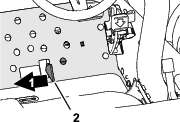
Important: If you ever remove the battery, ensure that the battery clamp bolts are installed with the bolt heads positioned on the bottom side and the nuts on the top side. If the clamp bolts are reversed, they may interfere with the hydraulic tubes when you shift the cutting units.
-
-
Coat both battery connections with Grafo 112X skin-over grease (Toro Part No. 505-47) or light grease to prevent corrosion.
-
Slide the rubber boot over the positive terminal to prevent a possible short from occurring.
-
Install the battery cover.
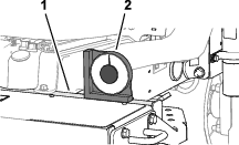
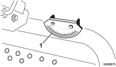
Checking the Slope Indicator
Parts needed for this procedure:
| Angle indicator (handheld) | 1 |
-
Park the machine on a flat, level surface.
-
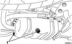
Verify that the machine is level by placing a handheld angle indicator (supplied with the machine) on the frame cross rail, by the fuel tank (Figure 6).
-
If the angle indicator does not read 0°, move the machine to a location where you can attain a 0° reading on the handheld angle indicator.
-
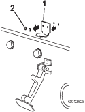
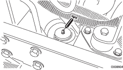
Check the slope indicator mounted on the steering tube of the machine (Figure 7).
Note: The slope indicator should read 0° when viewed from the operator’s position.
-
If the slope indicator does not read 0°, loosen the 2 screws and 2 locknuts securing the angle indicator to the mounting bracket, adjust the indicator to attain a 0° reading, and tighten the screws and nuts.
Installing the Roll Bar
Parts needed for this procedure:
| Roll-bar assembly | 1 |
| Flange-head bolt | 4 |
| Locknut | 4 |
| Hose clamp | 1 |
Warning
Operating the machine with a modified or damaged roll bar may not adequately protect you, causing possible injury or death in a rollover.
-
Do not install a damaged or modified roll bar on the machine.
-
Replace a damaged roll bar; do not repair or alter it.
-
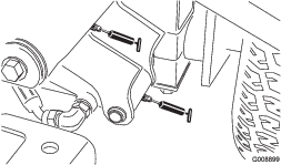
Lower the roll bar onto the traction unit mounting brackets, aligning the mounting holes. Ensure that the vent tube on the roll bar is on the left side of the machine (Figure 8).
-
Secure each side of the roll bar to the mounting brackets with 2 flange head bolts and 2 locknuts (Figure 8). Torque the fasteners to 81 N∙m (60 ft-lb).
-
Secure the fuel line vent hose to the vent tube on the roll bar with the hose clamp.
Caution
Starting the engine with the fuel line vent hose disconnected from the vent tube will cause fuel to flow from the hose, increasing the risk of fire or explosion. A fire or explosion from fuel can burn you and others and can cause property damage.
Connect the fuel line vent hose to the vent tube prior to starting the engine.
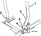
Installing the Front Lift Arms
Parts needed for this procedure:
| Lift arm kit (optional kit—order separately) | 1 |
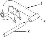
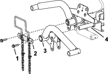
Preparing to Install the Lift Arms
-
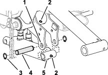
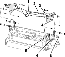
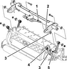
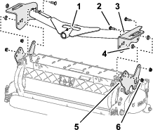
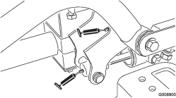
Insert a pivot rod into each lift arm and align the mounting holes (Figure 9).
-
Secure the pivot rods to the lift arms with 2 bolts (5/16 x 7/8 inch).
-
Torque the bolts to 37 to 45 N∙m (27 to 33 ft-lb).
-
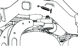
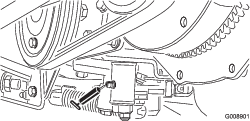
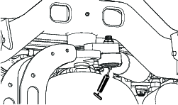
At the front of the machine, remove the 2 flange capscrews (1/2 x 2 inches) that secure the pivot-shaft link to the lift arm pivot shafts, and remove the link (Figure 10).
Note: Retain the pivot shaft link and capscrews.
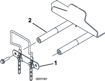
Assembling the Lift Arms to the Machine
-
Assemble the lift arms onto the lift arm pivot shafts as shown in Figure 11).
-
Assemble pivot-shaft link to the lift arm pivot shafts (Figure 11) with the 2 flange capscrews (1/2 x 2 inches) that you removed in Preparing to Install the Lift Arms.
-
Torque the capscrews to 95 N∙m (70 ft-lb).
Assembling the Lift Cylinder to the Left Lift Arm
Grease type: No. 2 lithium grease
Assembling the Lift Cylinder to the Right Lift Arm
Grease type: No. 2 lithium grease
-
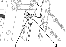
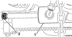
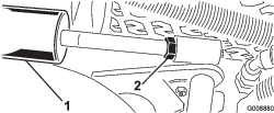
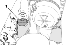
Align a drain pan below the hydraulic fittings of the lift cylinder (Figure 13).
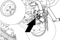
-
At the lift cylinder, loosen the straight swivel fitting of the return hose and the 90° swivel fitting of the lift hose (Figure 14).
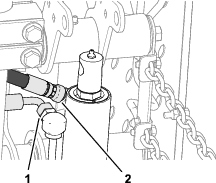
-
Wrap a rag around the hose fittings.
-
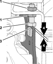
Slowly move the lift-cylinder rod until it aligns with the holes in the right lift-arm flanges (Figure 15).
Important: Some hydraulic fluid is forced out at the hose fittings when you move the lift-cylinder rod.
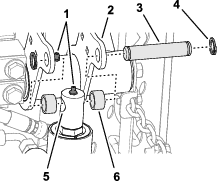
-
Assemble the rod to the flanges with the mounting pin, 2 spacers, and 2 snap rings (Figure 15).
-
Apply No. 2 lithium grease to the grease fittings of the lift arm and the hydraulic cylinder (Figure 15).
-
Torque the swivel fittings of the return and lift hoses to 37 to 45 N∙m (27 to 33 ft-lb).
-
Clean hydraulic fluid from the machine.
Installing the Carrier Frames to the Cutting Units
Parts needed for this procedure:
| Cutting Unit (optional part—order separately) | 3 |
Preparing the Cutting Units
-
Remove the cutting units from the cartons.
-
Adjust the cutting units as instructed in the Operator’s Manual for the cutting units.
Assembling the Carrier Frames for the Front Cutting Units
Cutting Unit with Links
Note: The front carrier frames are part of the optional lift arm kit.
-
Align the holes in the plates of the front-carrier frame with the holes in the cutting unit mounting plates (Figure 17).
-
Align a washer between the carrier plate and link (Figure 17), and loosely assemble the plates and spacer with a carriage bolt (3/8 x 2-1/4 inches), washer, and flange locknut (3/8 inch).
Note: If you are starting assembly at the back of the cutting unit, use the middle hole of the plate.
-
Repeat step 2 at the other plate holes and links.
-
Torque the flange locknuts to 37 to 45 N∙m (27 to 33 ft-lb).
-
Repeat steps 1 through 4 for the other front cutting unit and carrier frame.
Assembling the Cutting Unit and Rear Carrier Frame
Cutting Unit with Links
Note: The rear carrier frame is part of the optional lift arm kit.
-
Align the hole in the plates rear-carrier frame with the hole in the cutting unit mounting plates
-
Align a washer between the carrier plate and link (Figure 18), and loosely assemble the plates and spacer with a carriage bolt (3/8 x 2-1/4 inches), washer, and flange locknut (3/8 inch).
Note: If you are starting assembly at the back of the cutting unit, use the middle hole of the plate.
-
Repeat step 2 at the other plate holes and links.
-
Torque the flange locknuts to 37 to 45 N∙m (27 to 33 ft-lb).
Assembling the Carrier Frames for the Front Cutting Units
Cutting Unit with Mounting Plates
Note: The front carrier frames are part of the optional lift arm kit.
-
Align the holes in the plates of the front-carrier frame with the holes in the cutting unit mounting plates (Figure 19).
-
Align a spacer between the carrier plate and mounting plate (Figure 19), and loosely assemble the plates and spacer with a carriage bolt (3/8 x 1-1/4 inches) and flange locknut (3/8 inch).
Note: If you are starting assembly at the back of the cutting unit, use the middle holes of each plate.
-
Repeat step 2 at the other plate holes.
-
Torque the flange locknuts to 37 to 45 N∙m (27 to 33 ft-lb).
-
Repeat steps 1 through 4 for the other front cutting unit and carrier frame.
Assembling the Cutting Unit and Rear Carrier Frame
Cutting Unit with Mounting Plates
Note: The rear carrier frame is part of the optional lift arm kit.
-
Align the holes in the plates of the rear-carrier frame with the holes in the cutting unit mounting plates (Figure 15).

-
Align a spacer between the carrier plate and mounting plate (Figure 16), and loosely assemble the plates and spacer with a carriage bolt (3/8 x 1-1/4 inches) and flange locknut (3/8 inch).
Note: If you are starting assembly at the back of the cutting unit, use the middle holes of each plate.
-
Repeat step 2 at the other plate holes.
-
Torque the flange locknuts to 37 to 45 N∙m (27 to 33 ft-lb).
Installing the Cutting Units
-
Slide a thrust washer onto each front lift arm pivot rod.
-
Slide the cutting unit carrier frame onto the pivot rod and secure it with a lynch pin (Figure 21).
Note: On rear cutting unit, position the thrust washer between the rear of the carrier frame and the lynch pin.
-
Grease all the lift arm and carrier frame pivot points.
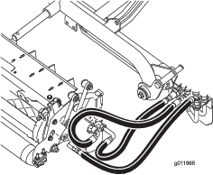
Important: Ensure that the hoses are free of twists or sharp bends and that the rear cutting unit hoses are routed as show in (Figure 22). Raise the cutting units and shift them to the left (Model 03171). The rear cutting unit hoses must not contact the traction cable bracket. Reposition the fittings and/or hoses if necessary.
-
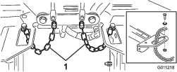
Route a tipper chain up through the slot on the end of each carrier frame. Secure the tipper chain to the top of the carrier frame with a bolt, a washer, and a locknut (Figure 23).
Installing the Cutting Unit Drive Motors
-
Position the cutting units in front of the lift arm pivot rods.
-
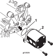
Remove the weight and O-ring (Figure 24) from the inside end of the right cutting unit.
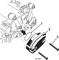
-
Remove the plug from the bearing housing on the outside end of the right cutting unit and install the weights and gasket.
-
Remove the shipping plug from the bearing housings on the remaining cutting units.
-
Insert the O-ring (supplied with the cutting unit) on the flange of the drive motor (Figure 25).
-
Mount the motor to the drive end of the cutting unit, and secure it with 2 capscrews provided with cutting unit (Figure 25).
Adjusting the Lift Arms
Checking Lift Arm and Rear Cutting Unit Clearance
-
Start the engine.
-
Raise the cutting units.
-
At the front cutting units, measure the distance between the left lift arm and the floor plate bracket, and the right lift arm and the floor plate bracket (Figure 26).
Note: The correct clearance is 5 to 8 mm (3/16 to 5/16 inch). If the clearance is not in this range, adjust the cutting unit lift cylinder; refer to Adjusting Lift Arm Clearance and Adjusting the Lift Arm Stop Bolts.
Important: A lack of clearance at the front plate bracket could damage the lift arms.
-
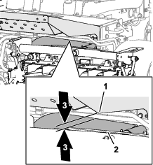
At the rear cutting unit, measure the clearance between the wear strap on the top of the rear cutting unit wear bar and the bumper stop (Figure 27).
Note: The correct clearance is 0.51 to 2.54 mm (0.02 to 0.10 inch). If the clearance is not in this range, adjust the cutting unit lift cylinder; refer to Adjusting the Rear Cutting Unit Clearance.
Important: A lack of clearance at the rear wear bar could damage the cutting unit.
-
Start the engine, lower the cutting units, shut off the engine, remove the key, and wait for all moving parts to stop.
Adjusting Lift Arm Clearance
-
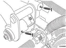
At each side of the machine, loosen the jam nuts and back off the lift arm-stop bolts (Figure 28).
-
Loosen the jam nut on the lift-cylinder rod (Figure 29).
-
Remove the pin from the rod end and rotate the clevis.
-
Install the pin and check the clearance.
-
Repeat steps 1 through 4 if necessary.
-
Start the engine, raise the cutting units, shut off the engine, remove the key and wait for all moving parts to stop.
-
Measure the distance between the left and right lift arms and the floor plate brackets.
Note: The correct clearance is 0.51 to 2.54 mm (0.02 to 0.10 inch).
-
Repeat steps 3 through 7 as needed.
-
Tighten the clevis jam nut.
-
Repeat steps 2 through 9 at the other side of the machine, then perform the Adjusting the Lift Arm Stop Bolts procedure.
Adjusting the Lift Arm Stop Bolts
Important: A lack of clearance at the stop bolts could damage the lift arms.
Note: If the rear lift arm clunks during transport, reduce the clearance.
-
Start the engine, raise the cutting units, shut off the engine, remove the key and wait for all moving parts to stop.
-
Adjust the stop bolt until you measure 0.13 to 1.02 mm (0.005 to 0.040 inches) between the stop bolt and the lift-arm plate.
-
Repeat step 2 at the stop bolt for the other lift arm.
-
Start the engine, lower the cutting units, shut off the engine, remove the key, and wait for all moving parts to stop.
Adjusting the Rear Cutting Unit Clearance
-
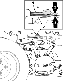
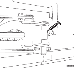
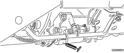
Loosen the jam nut of the lift cylinder (Figure 31).
-
Grasp the cylinder rod close to the nut with a pliers and rag, and rotate the rod.
Note: Shortening the rod reduces wear strap and bumper stop clearance.
-
Start the engine.
-
Raise the cutting units and measure the clearance between the wear strap on the top of the rear cutting unit wear bar and the bumper stop.
The correct clearance is 0.51 to 2.54 mm (0.02 to 0.10 inch).
-
Repeat steps 1 through 4 as needed.
-
Lower the cutting units, shut off the engine, remove the key, and wait for all moving parts to stop.
-
Tighten the jam nut.
Adjusting Tire Air Pressure
Adjust the tire air pressure at each of the tires; refer to Checking the Tire Pressure.
Note: The tires are over-inflated for shipping.
Installing the Hood Latch
CE Machines
Parts needed for this procedure:
| Lock bracket | 1 |
| Rivet | 2 |
| Washer | 1 |
| Screw (1/4 x 2 inches) | 1 |
| Locknut (1/4 inch) | 1 |
-
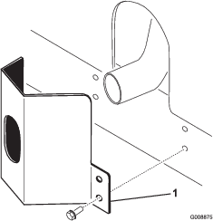
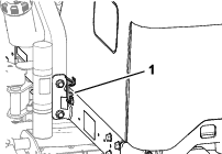
Unhook the hood latch from the hood-latch bracket.
-
Remove the rivets (2) securing the hood-latch bracket to the hood (Figure 32). Remove the hood-latch bracket from the hood.
-
While aligning the mounting holes, position the CE lock bracket and the hood-latch bracket onto the hood. The lock bracket must be against the hood (Figure 33). Do not remove the bolt and nut assembly from the lock bracket arm.
-
Align the washers with the holes on the inside of the hood.
-
Rivet the brackets and the washers to the hood (Figure 33).
-
Hook the latch onto the hood-latch bracket (Figure 34).
-
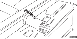
Screw the bolt into the other arm of hood-lock bracket to lock the latch in position (Figure 35).
Note: Tighten the nut and bolt until the bolt no longer moves forward and backward in the CE lock bracket.
Installing the Exhaust Guard
Installing the CE Decals
CE Machines
Parts needed for this procedure:
| Year of production decal | 1 |
| CE decal (Part No. 133-8095) | 1 |
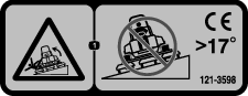
| Tilt danger decal (121-3598) |
Applying the Year of Production Decal and CE Decal
-
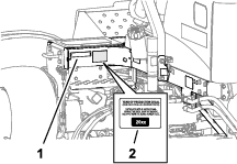
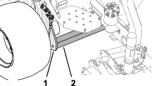
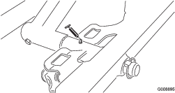
Wipe clean the left frame near the model/serial plate with alcohol, and allow the frame to dry (Figure 37).
-
Remove the backing and apply the Year of Production decal to the frame near the serial plate as shown in Figure 37.
-
Wipe clean the left frame near the hood lock with alcohol, and allow the frame to dry (Figure 38).
-
Remove the backing and apply the CE decal Part No. 133-8095 to the frame as shown in Figure 38.
Installing the Tipper Roller Kit (Optional)
Parts needed for this procedure:
| Tipper roller kit (not included) | 1 |
When cutting in higher heights of cut, install the Tipper Roller Kit.
-
Raise the cutting units all the way up.
-
Locate the frame bracket above the center cutting unit (Figure 40).
-
While pressing down on the front roller of the center cutting unit, determine which holes on the tipper bracket align with the frame bracket holes to attain the same roller contact when the tipper bracket is installed (Figure 40).
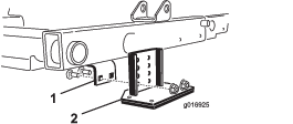
-
Lower the cutting units and mount the tipper bracket to the frame with the 2 carriage bolts and 2 nuts supplied with the kit (Figure 40).
Product Overview
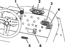
Traction Pedals
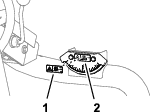
Mow/Transport Slide
Using your heel, move the mow/transport slide (Figure 42) left to the TRANSPORT position or right to the MOW position.
-
The cutting units only operate when the mow/transport slide is in the MOW position.
-
The cutting units do not lower when the mow/transport slide is in the TRANSPORT position.
Tilt-Steering Lever
Pull the tilt-steering lever (Figure 42) back to tilt the steering wheel to the desired position. Then push the lever forward to secure the position.
Indicator Slot
The slot in the operator platform (Figure 42) indicates when the cutting units are in the center position.
Slope Indicator
The slope indicator (Figure 42) indicates the side hill angle of the machine in degrees.
Control Console
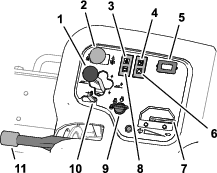
Cutting Unit Shift Lever—Raise/Lower
-
To lower the cutting units to the ground, push forward the cutting unit shift lever forward to the LOWER position (Figure 43).
Note: The cutting units do not lower unless the engine is running. You do not need to hold the lever in the forward position while the cutting units are lowered.
-
To raise the cutting units, pull the shift lever rearward to the RAISE position.
Note: The reels do not run while the cutting units are raised.
Cutting Unit Shift Lever—Side Shift
Model 03171
Move the lever to the right or left to move the cutting units in the same direction. Sideshift the cutting units only when they are raised or if they are on the ground and the machine is moving.
Danger
Shifting the cutting units downhill decreases machine stability. This could cause a rollover, which may result in personal injury or death.
Shift the cutting units uphill while on a side hill.
Cutting Unit Drive Switch
The cutting unit drive switch (Figure 43) has 2 positions: ENGAGE and DISENGAGE. The rocker switch operates a solenoid valve on the valve bank to drive the cutting units.
Oil Pressure Warning Light
The oil pressure warning light (Figure 43) glows if the engine oil pressure drops below a safe level.
Engine Coolant Temperature Warning Light
The temperature warning light (Figure 43) illuminates if the engine coolant temperature is high. At this temperature, the cutting units shut off. If the coolant temperature rises another 5.5°C (10°F), the engine shuts off to prevent further damage.
Hour Meter
The hour meter (Figure 43) indicates the total hours of machine operation. The hour meter starts to function whenever the key switch is on.
Glow-Plug Indicator
The glow-plug indicator light (Figure 43) illuminates when the glow plugs are energized.
Throttle
Move the throttle (Figure 43) forward to increase the engine speed and rearward to decrease the engine speed.
Alternator Light
The alternator light (Figure 43) shuts off when the engine runs. If the alternator light illuminates while the engine runs, check the charging system and repair it as necessary.
Ignition Switch
Use the ignition switch (Figure 43) to run the engine and lights. The ignition switch has 3 positions:
-
The SHUT OFF position shuts off the engine.
-
The RUN/PREHEAT position allows the engine to run or preheats the cylinder head of the engine.
-
The START position energizes the starter.
Note: When the key is in the RUN/PREHEAT position, the glow plug energizes and the indicator light illuminates for approximately 7 seconds.
Lift Lever Lock
Move the lift lever lock (Figure 43) rearward to prevent the cutting units from dropping.
Parking Brake
Whenever the engine is shut off, engage the parking brake (Figure 43) to prevent accidental movement of the machine. To engage the parking brake, pull up on the lever; to disengage the brake, push down the lever.
Note: The engine shuts off if you press the traction pedal with the parking brake engaged.
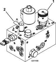
Mower Manifold
The mower manifold is located under the control-console cover (Figure 44).
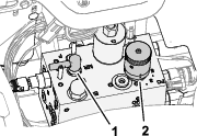
Reel Speed Knob
Use the reel speed knob of the mower manifold to adjust the clip rate (reel speed) of the cutting units (Figure 44).
-
Turn the reel speed knob counterclockwise to increase the reel speed.
-
Turn the knob clockwise to slow the reel speed.
Refer to Clip Rate (Reel Speed) and Adjusting Reel Speed for information on how to adjust the reel speed control.
Backlap Lever
The backlap lever to control the direction the cutting units rotate when you are mowing or when you backlap the reels and bedknives (Figure 44).
-
Rotate the backlap lever to the F position when mowing.
-
Rotate the lever to the R position when backlapping the cutting units.
Important: Do not change the backlap lever position while the reels are rotating.
Fuel Gauge
The fuel gauge (Figure 45) registers the amount of fuel in the tank.
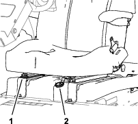
Seat Adjustment Lever
Move the lever (Figure 45) on the side of the seat outward, slide the seat to the desired position, and release the lever to lock the seat into position.
Note: Specifications and design are subject to change without notice.
| Transport width | 203 cm (80 inches) in 183 cm (72 inches) width of cut234 cm (92 inches) in 216 cm (85 inches) width of cut |
| Width of cut | 183 cm (72 inches) or 216 cm (85 inches) |
| Length | 248 cm (93 inch) |
| Height | 193 cm (76 inches) with ROPS |
| Net weight* | 844 kg (1,860 lb) |
| Fuel tank capacity | 28 L (7.5 US gallons). |
| Ground speed | Mow: 0 to 10 km/h (0 to 6 mph); Transport: 0 to 14 km/h (0 to 9 mph). Reverse: 0 to 6 km/h (0 to 4 mph) |
| * With cutting units and fluids | |
Attachments/Accessories
A selection of Toro approved attachments and accessories is available for use with the machine to enhance and expand its capabilities. Contact your Authorized Service Dealer or authorized Toro distributor or go to www.Toro.com for a list of all approved attachments and accessories.
To ensure optimum performance and continued safety certification of the machine, use only genuine Toro replacement parts and accessories. Replacement parts and accessories made by other manufacturers could be dangerous, and such use could void the product warranty.
Operation
Note: Determine the left and right sides of the machine from the normal operating position.
Before Operation
Before Operation Safety
General Safety
-
Never allow children or untrained people to operate or service the machine. Local regulations may restrict the age of the operator. The owner is responsible for training all operators and mechanics.
-
Become familiar with the safe operation of the equipment, operator controls, and safety signs.
-
Before you leave the operator’s position, do the following:
-
Park the machine on a level surface.
-
Disengage and lower the cutting units.
-
Engage the parking brake.
-
Shut off the engine and remove the key.
-
Wait for all movement to stop.
-
Allow the machine to cool before adjusting, servicing, cleaning, or storing it.
-
-
Know how to stop the machine and shut off the engine quickly.
-
Do not operate the machine without all guards and other safety protective devices in place and functioning properly on the machine.
-
Before mowing, always inspect the machine to ensure that the cutting units are in good working condition.
-
Inspect the area where you will use the machine and remove all objects that the machine could throw.
Fuel Safety
-
Use extreme care in handling fuel. It is flammable and its vapors are explosive.
-
Extinguish all cigarettes, cigars, pipes, and other sources of ignition.
-
Use only an approved fuel container.
-
Do not remove the fuel cap or fill the fuel tank while the engine is running or hot.
-
Do not add or drain fuel in an enclosed space.
-
Do not store the machine or fuel container where there is an open flame, spark, or pilot light, such as on a water heater or other appliance.
-
If you spill fuel, do not attempt to start the engine; avoid creating any source of ignition until the fuel vapors have dissipated.
Fuel Specification
Use only clean, fresh diesel fuel with ultra low (<15 ppm) or low (<1000 ppm) sulfur content. Purchase fuel in quantities that can be used within 180 days to ensure fuel freshness.
Important: If you use high-sulfur diesel fuel (sulfur content 0.50 % (5000 ppm) to 1.0 % (10000 ppm), change the engine oil and oil filter every 75 hours.
Use summer-grade diesel fuel (No. 2-D) at temperatures above -7°C (20°F) and winter-grade (No. 1-D or No. 1-D/2-D blend) below that temperature. Using winter-grade fuel at lower temperatures provides a lower flash point and cold flow characteristics, which eases starting and reduces plugging of the fuel filter.
Using summer-grade fuel above -7°C (20°F) contributes toward longer fuel pump life and increased power compared to winter-grade fuel.
Biodiesel
This machine can also use a biodiesel blended fuel of up to B20 (20% biodiesel, 80% petrodiesel). The petrodiesel portion should be low or ultra low sulfur. Observe the following precautions:
-
The biodiesel portion of the fuel must meet specification ASTM D6751 or EN14214.
-
The blended fuel composition should meet ASTM D975 or EN590.
-
Biodiesel blends may damage painted surfaces.
-
Use B5 (biodiesel content of 5%) or lesser blends in cold weather.
-
Monitor seals, hoses, gaskets in contact with fuel as they may degrade over time.
-
The fuel filter may plug up for a period after converting to biodiesel blends.
-
Contact a distributor for more information on biodiesel blended fuel.
Filling the Fuel Tank
Fuel tank capacity: approximately 28 L (7.5 US gallons)
-
Park the machine on a level surface, lower the cutting units, engage the parking brake, shut off the engine, and remove the key.
-
Clean the area around the fuel-tank cap (Figure 46).
-
Remove the fuel-tank cap.
-
Fill the tank to the bottom of the filler neck.
Note: Do not overfill the fuel tank.
-
Install the cap.
-
Wipe up any spilled fuel.
Performing Daily Maintenance
Before starting the machine each day, perform the Each Use/Daily procedures listed in .
Checking the Interlock System
| Maintenance Service Interval | Maintenance Procedure |
|---|---|
| Before each use or daily |
|
Caution
If safety interlock switches are disconnected or damaged, the machine could operate unexpectedly, causing personal injury.
-
Do not tamper with the interlock switches.
-
Check the operation of the interlock switches daily and replace any damaged switches before operating the machine.
Important: If your machine fails any of the interlock switch checks, contact your authorized Toro distributor.
Preparing the Machine
-
Drive the machine slowly to an open area.
-
Lower the cutting units, shut off the engine, and engage the parking brake.
Checking the Traction Pedal Start-Interlock
-
Sit in the operator’s seat.
-
Engage the parking brake.
-
Press the cutting unit drive switch to the DISENGAGE position.
-
Press the traction pedal.
-
Rotate the key to the START position.
Note: The starter should not crank the engine with the traction pedal pressed.
Checking the Cutting Unit Drive Switch Start-Interlock
-
Sit in the operator’s seat.
-
Engage the parking brake.
-
Press the cutting unit drive switch to the ENGAGE position.
-
Keep you foot off the traction pedal.
-
Rotate the key to the START position.
Note: The starter should not crank the engine with the cutting unit drive switch to the ENGAGE position.
Checking the Parking Brake and Seat Run-Interlock
-
Sit in the operator’s seat.
-
Engage the parking brake.
-
Press the cutting unit drive switch to the DISENGAGE position.
-
Keep you foot off the traction pedal.
-
Start the engine.
-
Disengage the parking brake.
-
Rise off the operator’s seat.
Note: The engine should shut off if you are out of the operator’s seat and the parking brake is disengaged.
Checking the Parking Brake and Traction Pedal Run-Interlock
-
Sit in the operator’s seat.
-
Engage the parking brake.
-
Press the cutting unit drive switch to the DISENGAGE position.
-
Keep you foot off the traction pedal.
-
Start the engine.
-
Press the traction pedal.
Note: The engine should shut off if the parking brake is ENGAGED and the traction pedal is pressed.
Checking the Seat and Traction Pedal Run-Interlock
-
Sit in the operator’s seat.
-
Engage the parking brake.
-
Press the cutting unit drive switch to the DISENGAGE position.
-
Keep you foot off the traction pedal.
-
Start the engine.
-
Disengage the parking brake.
-
Rise off the operator’s seat.
-
Press the traction pedal.
Note: The engine should shut off in 1 second if you are out of the operator’s seat and press the traction pedal.
During Operation
During Operation Safety
General Safety
-
The owner/operator can prevent and is responsible for accidents that may cause personal injury or property damage.
-
Wear appropriate clothing, including eye protection; long pants; substantial, slip-resistant footwear; and hearing protection. Tie back long hair and do not wear loose clothing or loose jewelry.
-
Do not operate the machine while ill, tired, or under the influence of alcohol or drugs.
-
Use your full attention while operating the machine. Do not engage in any activity that causes distractions; otherwise, injury or property damage may occur.
-
Before you start the engine, ensure that all drives are in neutral, the parking brake is engaged, and you are in the operating position.
-
Do not carry passengers on the machine and keep bystanders and children out of the operating area.
-
Operate the machine only in good visibility to avoid holes or hidden hazards.
-
Avoid mowing on wet grass. Reduced traction could cause the machine to slide.
-
Keep your hands and feet away from the cutting units.
-
Look behind and down before backing up to be sure of a clear path.
-
Use care when approaching blind corners, shrubs, trees, or other objects that may obscure your vision.
-
Stop the cutting units whenever you are not mowing.
-
Slow down and use caution when making turns and crossing roads and sidewalks with the machine. Always yield the right-of-way.
-
Operate the engine only in well-ventilated areas. Exhaust gases contain carbon monoxide, which is lethal if inhaled.
-
Do not leave a running machine unattended.
-
Before you leave the operator’s position, do the following:
-
Park the machine on a level surface.
-
Disengage and lower the cutting units.
-
Engage the parking brake.
-
Shut off the engine and remove the key.
-
Wait for all movement to stop.
-
Allow the machine to cool before adjusting, servicing, cleaning, or storing it.
-
-
Operate the machine only in good visibility and appropriate weather conditions. Do not operate the machine when there is the risk of lightning.
Rollover Protection System (ROPS) Safety
-
Do not remove any of the ROPS components from the machine.
-
Ensure that the seat belt is attached and that you can release it quickly in an emergency.
-
Always wear your seat belt.
-
Check carefully for overhead obstructions and do not contact them.
-
Keep the ROPS in safe operating condition by thoroughly inspecting it periodically for damage and keeping all the mounting fasteners tight.
-
Replace all damaged ROPS components. Do not repair or alter them.
Slope Safety
-
Slopes are a major factor related to loss of control and rollover accidents, which can result in severe injury or death. You are responsible for safe slope operation. Operating the machine on any slope requires extra caution.
-
Evaluate the site conditions to determine if the slope is safe for machine operation, including surveying the site. Always use common sense and good judgment when performing this survey.
-
Review the slope instructions, listed below, for operating the machine on slopes. Before you operate the machine, review the site conditions to determine whether you can operate the machine in the conditions on that day and at that site. Changes in the terrain can result in a change in slope operation for the machine.
-
Avoid starting, stopping, or turning the machine on slopes. Avoid making sudden changes in speed or direction. Make turns slowly and gradually.
-
Do not operate a machine under any conditions where traction, steering, or stability is in question.
-
Remove or mark obstructions such as ditches, holes, ruts, bumps, rocks, or other hidden hazards. Tall grass can hide obstructions. Uneven terrain could overturn the machine.
-
Be aware that operating the machine on wet grass, across slopes, or downhill may cause the machine to lose traction.
-
Use extreme caution when operating the machine near drop-offs, ditches, embankments, water hazards, or other hazards. The machine could suddenly roll over if a wheel goes over the edge or the edge caves in. Establish a safety area between the machine and any hazard.
-
Identify hazards at the base of the slope. If there are hazards, mow the slope with a pedestrian-controlled machine.
-
If possible, keep the cutting units lowered to the ground while operating on slopes. Raising the cutting units while operating on slopes can cause the machine to become unstable.
-
This triplex mower has a unique drive system for superior traction on hills. The uphill wheel does not spin out and limit traction like conventional triplex mowers. If you operate the machine on a side hill that is too steep, rollover will occur before losing traction.
-
When possible, mow up and down a hill rather than across it.
-
On side hills, shift the cutting units uphill (if equipped).
-
If the tires lose traction, disengage the blade(s) and proceed slowly straight down the slope.
-
If you must turn, turn slowly and gradually downhill, if possible.
Starting the Engine
Note: You may need to bleed the fuel system if any of the following situations have occurred; refer to Bleeding the Fuel System:
-
It is the initial startup of a new engine.
-
The engine has shut off because lack of fuel.
-
You performed maintenance for the fuel system components, such as replacing the fuel filter.
-
Ensure that the parking brake is engaged, and the reel drive switch is in the DISENGAGE position.
-
Remove your foot from the traction pedal and ensure that the pedal is in the NEUTRAL position.
-
Move the throttle lever to the 1/2 throttle position.
-
Insert the key into the switch and rotate it to the ON/PREHEAT position until the glow plug indicator light goes out (approximately 7 seconds); then rotate the key to the START position to engage the starter motor. Release the key when the engine starts.
Note: The key moves automatically to the ON/RUN position.
Important: To prevent overheating of the starter motor, do not engage the starter longer than 15 seconds. After 10 seconds of continuous cranking, wait 60 seconds before engaging the starter motor again.
-
When the engine is started for the first time or after an overhaul of the engine, operate the machine in forward and reverse for 1 to 2 minutes. Also operate the lift lever and cutting unit drive switch to ensure proper operation of all parts.
Note: Turn the steering wheel to the left and right to check the steering response, then shut the engine off and check for oil leaks, loose parts, and any other wear or damage.
Caution
Checking for oil leaks, loose parts, and other malfunctions could result in injury.
Shut off the engine and wait for all moving parts to stop before checking for oil leaks, loose parts, and other malfunctions.
Shutting Off the Engine
-
Move the throttle control to the IDLE position.
-
Engage the parking brake.
-
Move the cutting unit drive switch to DISENGAGE position.
-
Lower the cutting units.
-
Shut off the engine, remove the key, and wait for all moving parts to stop.
Cutting Grass with the Machine
-
Move the machine to the job site and align the machine outside the cutting area for the first cutting pass.
-
Ensure that the cutting-unit drive switch is pulled up (the DISENGAGE position); Cutting Unit Drive Switch.
-
Move the throttle to the FAST position; refer to Throttle.
-
Use the cutting-unit shift lever to lower the cutting units to the ground; refer to Cutting Unit Shift Lever—Raise/Lower.
-
Press the cutting-unit drive switch to prepare cutting units for operation (the ENGAGE position).
-
Use the cutting-unit shift lever to raise the cutting units off the ground.
-
Begin moving the machine toward the cutting area and lower the cutting units.
Note: The cutting units run.
-
Before reaching the turnaround location, pull back the cutting-unit shift lever only long enough to raise the cutting units, and release the control lever.
Important: Do not hold the cutting-unit shift lever back while turning.
-
Perform a tear-shaped turn to quickly line up for your next pass.
Driving the Machine in Transport Mode
-
Move the cutting unit drive switch to the DISENGAGE position.
-
Raise the cutting units to the transport position.
-
Move the mow/transport slide left to the TRANSPORT position.
Important: Be careful when driving between objects so that you do not accidentally damage the machine or the cutting units. Use extra care when operating the machine on slopes. Drive slowly and avoid sharp turns on slopes to prevent rollovers.
Note: You cannot lower the cutting units while operating the machine the transport mode.
Clip Rate (Reel Speed)
To achieve a consistent, high quality of cut and a uniform after-cut appearance, it is important that the reel speed be matched to the height of cut.
Important: If the reel speed is too slow, you may notice visible clip marks. If the reel speed is too fast, the cut may have a fuzzy appearance.
| 5-Blade Reel | 8-Blade Reel | 11-Blade Reel | |||||
|---|---|---|---|---|---|---|---|
| Height of Cut | 8 km/h(5 mph) | 9.6 km/h(6 mph) | 8 km/h(5 mph) | 9.6 km/h(6 mph) | 8 km/h(5 mph) | 9.6 km/h(6 mph) | |
| 63.5 mm | 2-1/2 inches | 3 | 3 | 3* | 3* | – | – |
| 60.3 mm | 2-3/8 inches | 3 | 4 | 3* | 3* | – | – |
| 57.2 mm | 2-1/4 inches | 3 | 4 | 3* | 3* | – | – |
| 54.0 mm | 2-1/8 inches | 3 | 4 | 3* | 3* | – | – |
| 50.8 mm | 2 inches | 3 | 4 | 3* | 3* | – | – |
| 47.6 mm | 1-7/8 inches | 4 | 5 | 3* | 3* | – | – |
| 44.5 mm | 1-3/4 inches | 4 | 5 | 3* | 3* | – | – |
| 41.3 mm | 1-5/8 inches | 5 | 6 | 3* | 3* | – | – |
| 38.1 mm | 1-1/2 inches | 5 | 7 | 3 | 4 | – | – |
| 34.9 mm | 1-3/8 inches | 5 | 8 | 3 | 4 | – | – |
| 31.8 mm | 1-1/4 inches | 6 | 9 | 4 | 4 | – | – |
| 28.8 mm | 1-1/8 inches | 8 | 9* | 4 | 5 | – | – |
| 25. mm | 1 inch | 9 | 9* | 5 | 6 | – | – |
| 22.2 mm | 7/8 inch | 9* | 9* | 5 | 7 | – | – |
| 19.1 mm | 3/4 inch | 9* | 9* | 7 | 9 | 6 | 7 |
| 15.9 mm | 5/8 inch | 9* | 9* | 9 | 9* | 7 | 7 |
| 12.7 mm | 1/2 inch | 9* | 9* | 9 | 9* | 8 | 8 |
| 9.5 mm | 3/8 inch | 9* | 9* | 9 | 9* | 9 | 9 |
|
* Toro does not recommend this height of cut and/or mowing speed. |
|||||||
|
Note: The higher the number, the higher the speed. |
|||||||
Adjusting Reel Speed
-
Verify the height-of-cut setting on the cutting units. Use the column of the Reel Speed Selection Chart listing either 5-blade, 8-blade, or 11-blade reels, and find the height-of-cut listing nearest the actual height-of-cut setting. Look across the chart to find the reel-speed number that corresponds to that height of cut.
-
Lift the cover from the control arm (Figure 48).
-
Turn the reel speed control knob (Figure 49) to the reel-speed number determined in Step 1.
-
Assemble the cover onto the control arm.
-
Operate the machine for several days, then examine the cut to ensure the quality of cut. The reel speed knob may be set 1 position on either side of the reel-speed number indicated on the chart to account for differences in grass condition, grass length removed, and personal preference.
Bleeding the Fuel System
-
Park the machine on a level surface, lower the cutting units, engage the parking brake, shut off the engine, and remove the key.
-
Ensure that the fuel tank is at least half full.
-
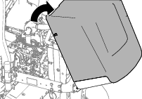
Unlatch and raise the hood.
-
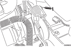
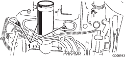
Open the air-bleed screw on the fuel-injection pump (Figure 50).
-
Turn the key in the ignition switch to the ON position.
The electric fuel pump runs, forcing air out around the air-bleed screw.
Note: Leave the key in the ON position until a solid stream of fuel flows out around the screw.
-
Tighten the screw and turn the ignition key to OFF.
Note: The engine should start after you follow the procedure above. However, if the engine does not start, air may be trapped between the injection pump and injectors; refer to Bleeding Air from the Injectors.
Operating Tips
Mowing Techniques
-
To begin cutting, engage the cutting units, then approach the mowing area slowly. Once the front cutting units are over the mowing area, lower the cutting units.
-
To achieve the professional straight-line cut and striping that is desirable for some applications, find a tree or other object in the distance and drive straight toward it.
-
As soon as the front cutting units reach the edge of the mowing area, lift the cutting units and perform a tear drop shaped turn to quickly line you up for your next pass.
-
To mow around bunkers, ponds, or other contours easily, use the Sidewinder and move the control lever left or right, depending on your mowing application. You can also shift the cutting units to vary tire tracking.
-
The cutting units tend to throw grass to the front or the rear of the machine. Front throw grass clippings when cutting smaller amounts of grass, which produces better after-cut appearance. To throw clippings to the front, simply close the rear shield on the cutting units.
Caution
To prevent personal injury or damage to the machine, do not open or close the cutting unit shields while the engine is running.
Shut off the engine and wait for all moving parts to stop before opening or closing the cutting unit shields.
-
When cutting larger amounts of grass, position the shields to just below horizontal. Do not open the shields too far or an excessive amount of clippings could build up on the frame, rear radiator screen, and engine area.
-
The cutting units are also equipped with balance weights on the non-motor end to give an even cut. You can add or remove weights if a mismatch occurs on your turf.
After Operation
After Operation Safety
General Safety
-
Park the machine on a level surface.
-
Disengage and lower the cutting units.
-
Engage the parking brake.
-
Shut off the engine and remove the key.
-
Wait for all movement to stop.
-
Allow the machine to cool before adjusting, servicing, cleaning, or storing it.
-
Clean grass and debris from the cutting units, drives, mufflers, cooling screens, and engine compartment to help prevent fires. Clean up oil or fuel spills.
-
Disengage the drive to the attachment whenever you are hauling or not using the machine.
-
Maintain and clean the seat belt(s) as necessary.
-
Do not store the machine or fuel container where there is an open flame, spark, or pilot light, such as on a water heater or on other appliances.
After Mowing
Wash the machine and grease it; refer to Washing the Machine and Greasing the Bearings and Bushings.
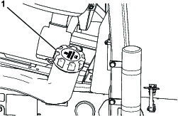
Towing the Machine
In case of an emergency, you can tow the machine for a short distance; however, Toro does not recommend this as a standard procedure.
Important: Do not tow the machine faster than 3 to 4 km/h (2 to 3 mph) because it may damage the drive system. If you must move the machine a considerable distance, transport it on a truck or trailer.
-
Unlatch and open the hood.
-
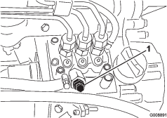
Near the right hood latch, rotate the handle bypass valve on the pump (Figure 51) and rotate the valve 90°.
-
Close and latch the hood.
-
Connect the tow vehicle to the machine at the tie-down points; refer to Identifying the Tie-Down Points.
-
Sit in the operator’s seat, and if needed, use the parking brake to control your machine while being towed.
Important: Do not start the engine while the bypass valve is open.
-
Before starting the engine, close the bypass valve by rotating it 90° (1/4 turn).
Identifying the Tie-Down Points
Hauling the Machine
-
Use full-width ramps for loading the machine onto a trailer or truck.
-
Tie the machine down securely.
Maintenance
Note: Determine the left and right sides of the machine from the normal operating position.
Note: Download a free copy of the electrical or hydraulic schematic by visiting www.Toro.com and searching for your machine from the Manuals link on the home page.
Important: Refer to your engine owner’s manual and cutting unit Operator's Manual for additional maintenance procedures.
Maintenance Safety
-
Before you leave the operator’s position, do the following:
-
Park the machine on a level surface.
-
Disengage and lower the cutting units.
-
Engage the parking brake.
-
Shut off the engine and remove the key.
-
Wait for all movement to stop.
-
Allow the machine to cool before adjusting, servicing, cleaning, or storing it.
-
-
Allow machine components to cool before performing maintenance.
-
If possible, do not perform maintenance while the engine is running. Keep away from moving parts.
-
Support the machine with jack stands whenever you work under the machine.
-
Carefully release pressure from components with stored energy.
-
Keep all parts of the machine in good working condition and all hardware tightened.
-
Replace all worn or damaged decals.
-
To ensure safe, optimal performance of the machine, use only genuine Toro replacement parts. Replacement parts made by other manufacturers could be dangerous, and such use could void the product warranty.
Recommended Maintenance Schedule(s)
| Maintenance Service Interval | Maintenance Procedure |
|---|---|
| After the first hour |
|
| After the first 10 hours |
|
| After the first 50 hours |
|
| Before each use or daily |
|
| Every 25 hours |
|
| Every 50 hours |
|
| Every 100 hours |
|
| Every 150 hours |
|
| Every 200 hours |
|
| Every 400 hours |
|
| Every 500 hours |
|
| Every 800 hours |
|
| Every 1,000 hours |
|
| Every 2,000 hours |
|
| Every 2 years |
|
Pre-Maintenance Procedures
Preparing for Maintenance
-
Park the machine on a level surface.
-
Lower the cutting units.
-
Engage the parking brake.
-
Shut off the engine, and remove the key.
-
Wait for all parts to stop moving.
Lifting the Front of the Machine
-
Chock the tires.
-
Jack the front of the machine under the square tube of the lower frame as closely to the side plate as possible.
-
Support the machine with jack stands rated for the weight of the machine under the square tube or wheel motors; refer to Specifications.
Lifting the Back of the Machine
Using a Hoist
-
Chock the tires.
-
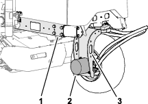
Secure the hoist to the tie-down loop of the rear-wheel fork (Figure 54).
-
Carefully raise the machine.
-
Support the machine with jack stands rated for the weight of the machine under the frame; refer to Specifications.
Lifting the Back of the Machine
Using a Jack
-
Chock the tires.
-
Jack the back of the machine under the rear wheel motor. (Figure 66).
-
Support the machine with jack stands rated for the weight of the machine under the frame; refer to Specifications.
Removing the Battery Cover
Remove the 2 knobs that secure the battery cover to the machine, and remove the cover (Figure 52).
Lubrication
Greasing the Bearings and Bushings
| Maintenance Service Interval | Maintenance Procedure |
|---|---|
| Every 50 hours |
|
| Every 500 hours |
|
Grease Specification: No. 2 lithium grease
The machine has grease fittings that must be lubricated regularly. Dusty and dirty operating conditions could cause dirt to get into the bearings and bushings, resulting in accelerated wear. Lubricate the grease fittings immediately after every washing, regardless of the interval specified.
-
Prepare the machine for maintenance; refer to Preparing for Maintenance.
-
Grease fittings at the locations and for quantities are as follows:
-
Rear cutting unit pivot (Figure 59)
-
Front cutting unit pivot (Figure 60)
-
Sidewinder cylinder ends (2 fittings; Model 03171 only—Figure 61)
-
Steering pivot (Figure 62)
-
Rear lift arm pivot and lift cylinder (2 fittings—Figure 63)
-
Left front lift arm pivot and lift cylinder (2 fittings—Figure 64)
-
Right front lift arm pivot and lift cylinder (2 fittings—Figure 65)
-
Neutral adjust mechanism (Figure 66)
-
Mow/transport slide (Figure 67)
-
Belt tension pivot (Figure 68)
-
Steering cylinder (Figure 69).
Note: If desired, install an additional grease fitting in the other end of the steering cylinder. Remove the tire, install the fitting, grease the fitting, remove the fitting, and install the plug (Figure 70).
-
Checking the Sealed Bearings
Bearings rarely fail from defects in materials or workmanship. The most common reason for failure is moisture and contamination working its way past the protective seals. Bearings that are greased rely upon regular maintenance to purge harmful debris from the bearing area. Sealed bearings rely on an initial fill of special grease and a robust integral seal to keep contaminants and moisture out of the rolling elements.
The sealed bearings require no lubrication or short-term maintenance. This minimizes routine service required and reduces the potential of turf damage due to grease contamination. These sealed bearing packages will provide good performance and life under normal use, but you should periodically inspect the bearing condition and seal integrity to avoid downtime. Inspect the bearings seasonally and replace the them if they are damaged or worn. Bearings should operate smoothly with no detrimental characteristics such as high heat, noise, looseness, or indications of corrosion (rust).
Due to the operating conditions these bearing/seal packages are subject to (i.e., sand, turf chemicals, water, impacts, etc.) they are considered normal wear items. Bearings that fail due to causes other than defects in materials or workmanship are typically not covered under the warranty.
Note: Bearing life can be negatively affected by improper wash-down procedures. Do not wash down the machine when it is still hot and avoid directing high-pressure or high-volume spray at the bearings.
Engine Maintenance
Engine Safety
-
Shut off the engine before checking the oil or adding oil to the crankcase.
-
Do not change the governor speed or overspeed the engine.
Engine Oil Specification
Use high-quality, low-ash engine oil that meets or exceeds the following specifications:
|
ACEA—E6 |
|
API—CH-4 or higher |
|
JASO—DH-2 |
Preferred oil viscosity: SAE 15W-40 [-17ºC (above 0°F)]
Alternate oil viscosity: SAE 10W-30 or 5W-30 (all temperatures)
Toro Premium Engine Oil is available from your authorized Toro distributor in either 15W-40 or 10W-30 viscosity grades.
Checking the Engine-Oil Level
| Maintenance Service Interval | Maintenance Procedure |
|---|---|
| Before each use or daily |
|
The engine is shipped with oil in the crankcase; however, check the oil level before and after you first start the engine.
Note: Toro Premium Engine oil is available from a distributor in either 15W-40 or 10W-30 viscosity. See the parts catalog for part numbers.
Note: The best time to check the engine oil is when the engine is cool before it has been started for the day. If it has already been run, allow the oil to drain back down to the sump for at least 10 minutes before checking. If the oil level is at or below the Add mark on the dipstick, add oil to bring the oil level to the Full mark. Do not overfill. If the oil level is between the Full and Add marks, you do not need to add oil.
-
Prepare the machine for maintenance; refer to Preparing for Maintenance.
-
Unlatch and open the hood.
-
Remove the dipstick (Figure 71) and wipe it with a clean rag.

-
Push the dipstick down into the dipstick tube and ensure that it is seated fully, then pull the dipstick out and check the oil level.
-
If the oil level is low, remove the oil-fill cap (Figure 72) and gradually add small quantities of oil, checking the level frequently, until the level reaches the Full mark on the dipstick.
Important: Keep the engine-oil level between the upper and lower limits on the dipstick. Overfilling or underfilling the engine oil may cause severe engine damage.
-
Install the oil-fill cap and dipstick.
-
Close and latch the hood.
Changing the Engine Oil and the Filter
| Maintenance Service Interval | Maintenance Procedure |
|---|---|
| After the first 50 hours |
|
| Every 150 hours |
|
Crankcase capacity: approximately 3.8 L (4.0 US qt) with the filter
-
Prepare the machine for maintenance; refer to Preparing for Maintenance.
-
Unlatch and open the hood, and wait for the engine to cool.
-
Remove either drain plug (Figure 73) and let the oil flow into a drain pan; when the oil stops flowing, install the drain plug.
-
Remove the oil filter (Figure 74).
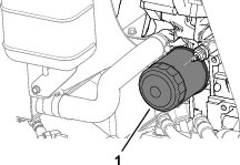
-
Apply a light coat of clean oil to the new filter seal and install the oil filter.
Note: Do not overtighten the filter.
-
Add oil to the crankcase; refer to Engine Oil Specification and Checking the Engine-Oil Level.
-
Close and latch the hood.
Servicing the Air Cleaner
| Maintenance Service Interval | Maintenance Procedure |
|---|---|
| Every 200 hours |
|
Removing the Air Filter
-
Check the air cleaner body for damage which could cause an air leak. Replace it if it is damaged. Check the whole intake system for leaks, damage, or loose hose clamps.
-
Service the air cleaner at the recommended service interval or earlier if engine performance declines due to extremely dusty, dirty conditions. Changing the air filter before it is necessary only increases the chance of dirt entering the engine when the filter is removed.
-
Ensure that the cover is seated correctly and seals with the air-cleaner body.
-
Prepare the machine for maintenance; refer to Preparing for Maintenance.
-
Open the hood.
-
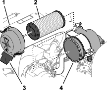
Release the latches that secure the air-cleaner cover to the air-cleaner body (Figure 75).
-
Remove the cover from the air-cleaner body.
-
Before removing the filter, use low-pressure air—276 kPa (40 psi), clean and dry—to help remove large accumulations of debris packed between the outside of primary filter and the canister. Avoid using high-pressure air which could force dirt through the filter into the intake tract. This cleaning process prevents debris from migrating into the intake when you remove the primary filter.
-
Remove the filter element (Figure 75).
Note: Cleaning the used element may damage the filter media.
-
Remove the rubber outlet valve (Figure 75) from the dirt ejection port of the air-cleaner cover.
-
Clean the ejection and outlet valve, and install the outlet valve to the port.
Installing the Air Filter
-
Inspect the new filter for shipping damage and check the sealing end of the filter and the body.
Important: Do not use a damaged element.
-
Insert the new filter by applying pressure to the outer rim of the element to seat it in the canister.
Important: Do not apply pressure to the flexible center of the filter.
-
Install the cover orienting the rubber outlet valve in a downward position—between approximately 5 o'clock to 7 o'clock when viewed from the end.
-
Secure the cover with the 2 latches.
-
Close and latch the hood.
Fuel System Maintenance
Servicing the Fuel Tank
| Maintenance Service Interval | Maintenance Procedure |
|---|---|
| Every 2 years |
|
Prepare the machine for maintenance; refer to Preparing for Maintenance.
Drain and clean the tank if the fuel system becomes contaminated or if the machine will be stored for an extended period. Use clean fuel to flush out the tank.
Inspecting the Fuel Lines and Fittings
| Maintenance Service Interval | Maintenance Procedure |
|---|---|
| Every 400 hours |
|
-
Prepare the machine for maintenance; refer to Preparing for Maintenance.
-
Unlatch and open the hood.
-
Inspect the fuel lines and fittings for deterioration, damage, or loose connections.
Note: Repair or replace any damaged or worn the fuel lines or fittings.
-
Close and latch the hood.
Draining the Water Separator
| Maintenance Service Interval | Maintenance Procedure |
|---|---|
| Before each use or daily |
|
-
Prepare the machine for maintenance; refer to Preparing for Maintenance.
-
Unlatch and open the hood, and wait for the engine to cool.
-
Place a clean container under the fuel filter.
-
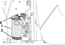
Loosen the drain valve on the bottom of the filter canister (Figure 76).
-
Tighten the valve after draining.
-
Start the engine, check for leaks, and shut off the engine.
Note: Repair all fuel leaks.
-
Close and latch the hood.
Changing the Fuel Filter Canister
| Maintenance Service Interval | Maintenance Procedure |
|---|---|
| Every 400 hours |
|
-
Prepare the machine for maintenance; refer to Preparing for Maintenance.
-
Unlatch and open the hood, and wait for the engine to cool.
-
Clean the area where the filter canister mounts (Figure 76).
-
Remove the filter canister and clean the mounting surface.
-
Lubricate the gasket on the filter canister with clean oil.
-
Install the filter canister by hand until the gasket contacts the mounting surface; then rotate an additional 1/2 turn.
-
Start the engine, check for leaks, and shut off the engine.
Note: Repair all fuel leaks.
-
Close and latch the hood.
Bleeding Air from the Injectors
Note: Use this procedure only if the fuel system has been purged of air through normal priming procedures and the engine does not start; refer to Bleeding the Fuel System.
-
When possible, preform each step in Preparing for Maintenance.
-
Unlatch and open the hood, and if the engine is hot wait for it to cool.
-
Loosen the tube nut for the fuel line to the No. 1 fuel-injector nozzle.
-
Move the throttle to the FAST position.
-
Turn the key in the key switch to the START position and watch the fuel flow around the connector. Turn the key to the OFF position when there is a continuous flow.
Important: To prevent overheating of the starter motor, do not engage the starter for longer than 15 seconds. After 10 seconds of continuous cranking, wait 60 seconds before engaging the starter motor again.
-
Tighten the tube nut securely.
-
Clean any fuel from the engine.
-
Repeat steps 3 through 7 for the remaining fuel-injector nozzles.
-
Start the engine, check for leaks, and shut off the engine.
Note: Repair all fuel leaks.
-
Close and latch the hood.
Electrical System Maintenance
Electrical System Safety
-
Disconnect the battery before repairing the machine. Disconnect the negative terminal first and the positive last. Connect the positive terminal first and the negative last.
-
Charge the battery in an open, well-ventilated area, away from sparks and flames. Unplug the charger before connecting or disconnecting the battery. Wear protective clothing and use insulated tools.
Servicing the Battery
| Maintenance Service Interval | Maintenance Procedure |
|---|---|
| Every 25 hours |
|
Danger
Battery electrolyte contains sulfuric acid which is fatal if consumed and causes severe burns.
-
Do not drink electrolyte and avoid contact with your skin, eyes, or clothing. Wear eye protection and rubber gloves.
-
Fill the battery where clean water is always available for flushing the skin.
Warning
Incorrect battery cable routing could damage the tractor and cables, causing sparks. Sparks can cause the battery gasses to explode, resulting in personal injury.
-
Always disconnect the negative (black) battery cable before disconnecting the positive (red) cable.
-
Always connect the positive (red) battery cable before connecting the negative (black) cable.
-
Prepare the machine for maintenance; refer to Preparing for Maintenance.
-
Remove the battery cover; refer to Removing the Battery Cover.
-
Remove the filler caps of the battery.
-
Maintain the battery electrolyte level in the battery cells with distilled or demineralized water.
Note: Do not fill the cells above the bottom of the split ring inside each cell.
-
Install the filler caps with the vents pointing to the rear (toward the fuel tank).
-
Clean the top of the battery by washing it periodically with a brush dipped in ammonia or bicarbonate of soda solution. Flush the top surface with water after cleaning.
Important: Do not remove the filler caps while cleaning.
-
Check the battery cable clamps and battery posts for corrosion. If corrosion occurs, perform the following:
-
Disconnect the negative (–) battery cable.
-
Disconnect the positive (+) battery cable.
-
Clean the clamps and posts separately.
-
Connect the positive (+) battery cable.
-
Connect the negative (–) battery cable.
-
Coat the clamps and terminals with battery terminal protector.
-
-
Check that the battery cable clamps are tight on the battery posts.
-
Install the battery cover.
Note: Store the machine where the temperature is cooler rather than warmer to prevent the battery from discharging more rapidly.
Drive System Maintenance
Checking the Tire Pressure
| Maintenance Service Interval | Maintenance Procedure |
|---|---|
| Before each use or daily |
|
Danger
Low tire pressure decreases machine side hill stability. This could cause a rollover, which may result in personal injury or death.
Do not under-inflate the tires.
Note: Maintain the recommended pressure in all tires to ensure a good quality of cut and proper machine performance.
-
Measure the air pressure in each tire. The correct air pressure in the tires is 97 to 110 kPa (14 to 16 psi).
-
If needed, add air to of remove air from the tires until you measure 97 to 110 kPa (14 to 16 psi).
Torquing the Wheel Nuts
| Maintenance Service Interval | Maintenance Procedure |
|---|---|
| After the first hour |
|
| After the first 10 hours |
|
| Every 200 hours |
|
Torque the wheel nuts in a crossing pattern to 61 to 88 N∙m (45 to 65 ft-lb).
Warning
Failure to maintain proper torque of the wheel nuts could result in personal injury.
Ensure that the wheel nuts are torqued to 61 to 88 N∙m (45 to 65 ft-lb).
Adjusting the Traction Drive for Neutral
If the machine moves when the traction pedal is in the NEUTRAL position, adjust the traction cam.
-
Park the machine on a level surface, lower the cutting units, engage the parking brake, shut off the engine, and remove the key from the ignition switch.
-
Raise a front wheel and a rear wheel off the floor and place support blocks under the frame.
Warning
If the machine is not supported adequately, it may accidentally fall, injuring anyone under the machine.
Raise a front wheel and the rear wheel off the ground; otherwise, the machine will move during adjustment.
-
Loosen the locknut on the traction adjustment cam (Figure 79).
Warning
The engine must be running so that you can make a final adjustment of the traction adjustment cam. Contact with hot or moving parts can result in personal injury.
Keep your hands, feet, face, and other body parts away from the muffler, other hot parts of the engine, and rotating parts.
-
Start the engine and rotate the cam hex in both directions to determine the mid position of the neutral span.
-
Tighten the locknut securing the adjustment.
-
Shut off the engine.
-
Remove the support blocks and lower the machine to the shop floor. Test drive the machine to ensure that it does not move when the traction pedal is in neutral.
Cooling System Maintenance
Cooling System Safety
-
Swallowing engine coolant can cause poisoning; keep out of reach from children and pets.
-
Discharge of hot, pressurized coolant or touching a hot radiator and surrounding parts can cause severe burns.
-
Always allow the engine to cool at least 15 minutes before removing the radiator cap.
-
Use a rag when opening the radiator cap, and open the cap slowly to allow steam to escape.
-
Coolant Specification
The coolant reservoir is filled at the factory with a 50/50 solution of water and ethylene glycol base extended-life coolant. Check the coolant level before you first start the engine and daily thereafter; refer to Checking the Coolant Level.
The following commercially available coolants or a manufacturer-specified equivalent meeting the long-life coolant specification:
|
Ford (Motorcraft™) |
WSS-M97B44-D |
|
FCA—Chrysler (Mopar™) |
MS-12106 |
|
General Motors (AC Delco™) |
GM6277M (Dex-Cool™) |
|
GMW 3420 |
|
|
Volkswagen |
G12 |
|
G12+ |
|
|
G12++ |
|
|
Coolants meeting technical standards ASTM D3306 or D4985, or SAE J1034, J814, or 1941. |
|
|
Important: Do not rely on the color of the coolant to identify the difference between conventional (IAT) and extended-life (OAT) coolant types.Coolant manufacturers may dye extended-life coolant (OAT) in one of the following colors: red, pink, orange, yellow, blue, teal, violet, and green. |
|
|
Ethylene-Glycol Coolant Type |
Corrosion Inhibitor Type |
Service Interval |
|
Extended-life antifreeze |
Organic-acid technology (OAT) |
5 years |
|
Conventional antifreeze (green) |
Inorganic-acid technology (IAT) |
2 years |
Note: When adding coolant to the machine, you will not damage the cooling system by mixing conventional (IAT) antifreeze with extended-life (OAT) antifreeze. However, mixing antifreeze types degrades the long life/extended life attribute of the OAT formulation.
Important: The service interval of conventional (IAT) and extended-life (OAT) blended-coolant mixture—at any ratio—lasts as long as the coolant with the shortest service interval: 2 years.
Checking the Coolant Level
| Maintenance Service Interval | Maintenance Procedure |
|---|---|
| Before each use or daily |
|
Cooling system capacity: approximately 5.7 L (6 US qt)
Caution
If the engine has been running, the pressurized, hot coolant can escape and cause burns.
-
Do not open the radiator cap when the engine is running.
-
Use a rag when opening the radiator cap, and open the cap slowly to allow steam to escape.
-
Prepare the machine for maintenance; refer to Preparing for Maintenance.
-
Unlatch and open the hood.
-
Check the coolant level in the expansion tank (Figure 80).
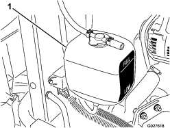
Note: With a cold engine, the coolant level should be approximately midway between the marks on the side of the tank.
-
If the coolant level is low remove the expansion tank cap, add the specified coolant to the tank until the coolant level is midway between the marks on the side of the tank, and assemble the cap to the tank.
Important: Do not overfill the expansion tank.
-
Close and latch the hood.
Cleaning the Engine Cooling System
| Maintenance Service Interval | Maintenance Procedure |
|---|---|
| Before each use or daily |
|
| Every 2 years |
|
Remove debris from the oil cooler and radiator daily. Clean them more frequently in dirty conditions.
-
Prepare the machine for maintenance; refer to Preparing for Maintenance.
-
Raise the hood.
-
Clean the engine area thoroughly of all debris.
-
Remove the lower radiator shield (Figure 81).
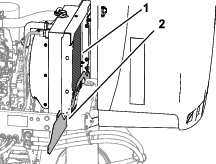
-
Clean both sides of the radiator area thoroughly with water or compressed air (Figure 81).
-
Install the lower radiator shield.
-
Close and latch the hood.
Brake Maintenance
Adjusting the Parking Brake
| Maintenance Service Interval | Maintenance Procedure |
|---|---|
| Every 200 hours |
|
-
Prepare the machine for maintenance; refer to Preparing for Maintenance.
-
Loosen the setscrew securing the knob to the parking-brake lever (Figure 82).
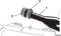
-
Rotate the knob until a force of 133 to 178 N (30 to 40 lb) is required to actuate the lever.
-
Tighten the setscrew.
Belt Maintenance
Servicing the Engine Belts
| Maintenance Service Interval | Maintenance Procedure |
|---|---|
| After the first 10 hours |
|
| Every 100 hours |
|
Tensioning the Alternator/Fan Belt
-
Prepare the machine for maintenance; refer to Preparing for Maintenance.
-
Unlatch and open the hood.
-
Check the belt tension by pressing the belt midway between the alternator and crankshaft pulleys.
Note: With 98 N (22 lb) of force, the belt should deflect 11 mm (7/16 inch).
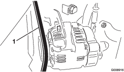
-
If the deflection is incorrect, complete the following procedure to tension the belt:
-
Loosen the bolt securing the brace to the engine and the bolt securing the alternator to the brace.
-
Insert a pry bar between the alternator and engine and pry the alternator outward.
-
When you achieve proper belt tension, tighten the alternator and brace bolts to secure the adjustment.
-
-
Close and latch the hood.
Replacing the Hydrostat Drive Belt
-
Insert a nut driver or small piece of tubing onto the end of the belt tensioning spring.
Warning
When you replace the hydrostat drive belt, you must release the tension on the spring, which is under a heavy load. Releasing the tension on the spring improperly may result in serious personal injury.
Be careful when releasing the tension on the spring.
-
Push down the end of the belt-tension spring down and out of the notch in the tab of the pump mount, and move the spring end forward (Figure 84).
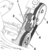
-
Replace the belt.
-
Push down the end of the belt-tension spring, and inward, and align it into the notch in the pump mount tab.
Controls System Maintenance
Adjusting Mow Ground Speed
-
Prepare the machine for maintenance; refer to Preparing for Maintenance.
-
Loosen the jam nut for the speed stop screw.
-
Adjust the speed stop screw as follow:
Note: The mow speed is set at the factory to 9.7 km/h (6 mph).
-
To decrease the mow speed, rotate the speed stop screw (Figure 85) clockwise.
-
To increase the mow speed, rotate the speed stop screw counterclockwise.
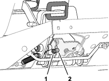
-
-
Hold the stop screw and tighten the jam nut.
-
Test drive the machine to confirm the maximum mow speed adjustment.
Adjusting the Throttle
-
Prepare the machine for maintenance; refer to Preparing for Maintenance.
-
Unlatch and open the hood.
-
Position the throttle lever rearward so that it stops against the control panel slot.
-
Loosen the throttle cable connector on the injection pump lever arm (Figure 86).
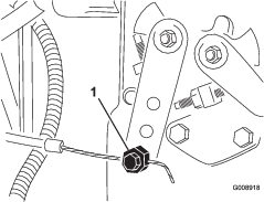
-
Hold the injection pump lever arm against the low idle stop and tighten the cable connector.
-
Loosen the screws securing the throttle control to the control panel.
-
Push the throttle control lever all the way forward.
-
Slide the stop plate until it contacts the throttle lever and tighten the screws securing the throttle control to the control panel.
-
If the throttle does not stay in position during operation, torque the locknut, used to set the friction device on the throttle lever, to 5 to 6 N∙m (44 to 53 in-lb).
Note: The maximum force required to operate the throttle lever should be 89 N (20 lb).
-
Close and latch the hood.
Hydraulic System Maintenance
Hydraulic System Safety
-
Seek immediate medical attention if fluid is injected into skin. Injected fluid must be surgically removed within a few hours by a doctor.
-
Ensure that all hydraulic-fluid hoses and lines are in good condition and all hydraulic connections and fittings are tight before applying pressure to the hydraulic system.
-
Keep your body and hands away from pinhole leaks or nozzles that eject high-pressure hydraulic fluid.
-
Use cardboard or paper to find hydraulic leaks.
-
Safely relieve all pressure in the hydraulic system before performing any work on the hydraulic system.
Checking the Hydraulic Lines and Hoses
| Maintenance Service Interval | Maintenance Procedure |
|---|---|
| Before each use or daily |
|
Check the hydraulic lines and hoses for leaks, kinked lines, loose mounting supports, wear, loose fittings, weather deterioration, and chemical deterioration. Make all necessary repairs before operating.
Hydraulic Fluid Specifications
The reservoir is filled at the factory with high-quality hydraulic fluid. Check the level of the hydraulic fluid before you first start the engine and daily thereafter; refer to Checking the Hydraulic Fluid.
Recommended hydraulic fluid: Toro PX Extended Life Hydraulic Fluid; available in 19 L (5 US gallon) pails or 208 L (55 US gallon) drums.
Note: A machine using the recommended replacement fluid requires less frequent fluid and filter changes.
Alternative hydraulic fluids: If Toro PX Extended Life Hydraulic Fluid is not available, you may use another conventional, petroleum-based hydraulic fluid having specifications that fall within the listed range for all the following material properties and that it meets industry standards. Do not use synthetic fluid. Consult with your lubricant distributor to identify a satisfactory product.
Note: Toro does not assume responsibility for damage caused by improper substitutions, so use products only from reputable manufacturers who will stand behind their recommendation.
| Material Properties: | ||
| Viscosity, ASTM D445 | cSt @ 40°C (104°F) 44 to 48 | |
| Viscosity Index ASTM D2270 | 140 or higher | |
| Pour Point, ASTM D97 | -37°C to -45°C (-34°F to -49°F) | |
| Industry Specifications: | Eaton Vickers 694 (I-286-S, M-2950-S/35VQ25 or M-2952-S) | |
Note: Many hydraulic fluids are almost colorless, making it difficult to spot leaks. A red dye additive for the hydraulic fluid is available in 20 ml (0.67 fl oz) bottles. A bottle is sufficient for 15 to 22 L (4 to 6 US gallons) of hydraulic fluid. Order Part No. 44-2500 from your authorized Toro distributor.
Important: Toro Premium Synthetic Biodegradable Hydraulic Fluid is the only synthetic biodegradable fluid approved by Toro. This fluid is compatible with the elastomers used in Toro hydraulic systems and is suitable for a wide-range of temperature conditions. This fluid is compatible with conventional mineral oils, but for maximum biodegradability and performance, the hydraulic system should be thoroughly flushed of conventional fluid. The oil is available in 19 L (5 US gallon) pails or 208 L (55 US gallon) drums from your authorized Toro distributor.
Checking the Hydraulic Fluid
| Maintenance Service Interval | Maintenance Procedure |
|---|---|
| Before each use or daily |
|
The reservoir is filled at the factory with high-quality hydraulic fluid. The best time to check the hydraulic oil is when the fluid is cold. The machine should be in its transport configuration.
-
Prepare the machine for maintenance; refer to Preparing for Maintenance.
-
Clean the area around the filler neck and cap of the hydraulic-fluid tank (Figure 87) and remove the cap.
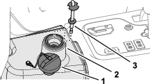
-
Remove the dipstick from the filler neck and wipe it with a clean rag.
-
Insert the dipstick into the filler neck; then remove it and check the fluid level.
Note: The fluid level should be within 6 mm (1/4 inch) of the mark on the dipstick.
-
If the level is low, add the specified fluid to raise the level to the full mark; refer to Hydraulic Fluid Specifications.
Important: Do not overfill the hydraulic reservoir.
-
Install the dipstick and cap onto the filler neck.
Hydraulic Fluid Capacity
13.2 L (3.5 US gallons); refer to Hydraulic Fluid Specifications
Changing the Hydraulic Fluid
| Maintenance Service Interval | Maintenance Procedure |
|---|---|
| Every 800 hours |
|
| Every 2,000 hours |
|
Warning
Hot hydraulic fluid can cause severe burns.
Allow the hydraulic fluid to cool before performing any maintenance to the hydraulic system.
If the fluid becomes contaminated, contact your authorized Toro distributor because the system must be flushed. Contaminated fluid looks milky or black when compared to clean oil.
-
Prepare the machine for maintenance; refer to Preparing for Maintenance.
-
Disconnect the hydraulic hose (Figure 88) or remove the hydraulic filter (Figure 89) and drain the hydraulic fluid into a drain pan.
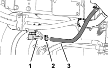
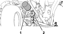
-
Install the hydraulic hose when hydraulic fluid stops draining.
-
Fill the reservoir (Figure 90) with approximately 22.7 L (6 US gallons) of hydraulic fluid; refer to Hydraulic Fluid Specifications.
Important: Use only the hydraulic fluids specified. Other fluids could cause system damage.
-
Install the dipstick and cap onto the filler neck.
-
Start the engine and use all the hydraulic controls to distribute the hydraulic fluid throughout the system.
-
Check for leaks; then shut off the engine.
-
Check the fluid level and add enough to raise the level to Full mark on the dipstick.
Important: Do not overfill the reservoir.
Changing the Hydraulic Filter
| Maintenance Service Interval | Maintenance Procedure |
|---|---|
| Every 800 hours |
|
| Every 1,000 hours |
|
Warning
Hot hydraulic fluid can cause severe burns.
Allow the hydraulic fluid to cool before performing any maintenance to the hydraulic system.
Use a genuine Toro replacement filter (Part No. 86-3010).
Important: Use of any other filter may void the warranty on some components.
-
Prepare the machine for maintenance; refer to Preparing for Maintenance.
-
Clean around the filter mounting area. Place a drain pan under the filter (Figure 91) and remove the filter.
-
Lubricate the new filter gasket and fill the filter with hydraulic fluid.
-
Ensure that the filter mounting area is clean. Screw the filter on until the gasket contacts the mounting plate; then tighten the filter 1/2 turn.
-
Start the engine and let it run for about 2 minutes to purge air from the system. Shut off the engine and check for leaks.
Cutting Unit System Maintenance
Blade Safety
A worn or damaged blade or bedknife can break, and a piece could be thrown toward you or bystanders, resulting in serious personal injury or death.
-
Inspect the blades and bedknives periodically for excessive wear or damage.
-
Use care when checking the blades. Wear gloves and use caution when servicing them. Only replace or backlap the blades and bedknives; never straighten or weld them.
-
On machines with multiple cutting units, take care when rotating a cutting unit; it can cause the reels in the other cutting units to rotate.
Checking the Reel-to-Bedknife Contact
| Maintenance Service Interval | Maintenance Procedure |
|---|---|
| Before each use or daily |
|
Check the reel-to-bedknife contact even if the quality of cut had been acceptable previously. There must be light contact across the full length of the reel and bedknife; refer to Adjusting Reel to Bedknife in the cutting unit operator’s manual.
Backlapping the Cutting Units
Warning
Contact with the cutting units or other moving parts can result in personal injury.
-
Keep your fingers, hands, and clothing away from the cutting units and other moving parts.
-
Never attempt to turn the cutting units by hand or foot while the engine is running.
Note: Additional instructions and procedures on backlapping are available in the Toro Reel Mower Basics (with sharpening guidelines), Form 09168SL.
Preparing the Machine
-
Prepare the machine for maintenance; refer to Preparing for Maintenance.
-
Make the initial reel-to-bedknife adjustments appropriate for backlapping; refer to the cutting unit Operator's Manual.
-
Lift the magnetically mounted console cover (Figure 92) to expose the mower manifold.
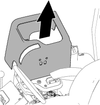
-
Move the backlap lever to the R (backlap) position (Figure 93).
Lapping the Reels and Bedknife
Danger
Changing the engine speed while backlapping may cause the cutting units to stall.
-
Never change the engine speed while backlapping
-
Backlap only at idle engine speed.
Note: The seat switch is bypassed when the backlap control is in the backlap position. You do not need to be in the seat, but the parking brake must be engaged for the engine to run.
-
Start the engine and allow it to run at low idle speed.
-
Press the cutting unit drive switch to the ENGAGE position.
-
Apply lapping compound to the reel with a long-handle brush.
Danger
Contacting the cutting units when they are moving could cause personal injury.
To avoid personal injury, be certain that you are clear of the cutting units before proceeding.
Important: Never use a short-handled brush.
-
If you need to make an adjustment to the cutting units while backlapping, perform the following steps:
-
Press the cutting unit drive switch to the DISENGAGE position.
-
Shut off the engine and remove the key.
-
Adjust to the cutting units.
-
Repeat steps 1 through 3.
-
-
Repeat steps 3 for the other cutting units that you want to backlap.
Finishing Backlapping
-
Press the cutting unit control switch to the DISENGAGE position.
-
Shut off the engine.
-
Move the backlap lever to the F (mow) position (Figure 94).
Important: If you do not change backlap lever to the F (mow) position after backlapping, the cutting units will not function properly.
-
Assemble the console cover to the control console.
-
Wash all lapping compound off from the cutting units.
-
For a better cutting edge, run a file across the front face of the bedknife after lapping.
Note: This removes any burrs or rough edges that may have built up on the cutting edge.
Cleaning
Washing the Machine
Wash the machine as needed using water alone or with a mild detergent. You may use a rag when washing the machine.
Important: Do not use brackish or reclaimed water to clean the machine.
Important: Do not use power-washing equipment to wash the machine. Power-washing equipment may damage the electrical system, loosen important decals, or wash away necessary grease at friction points. Avoid excessive use of water near the control panel, engine, and battery.
Important: Do not wash the machine with the engine running. Washing the machine with the engine running may result in internal engine damage.
Storage
Storage Safety
-
Before you leave the operator’s position, do the following:
-
Park the machine on a level surface.
-
Disengage and lower the cutting units.
-
Engage the parking brake.
-
Shut off the engine and remove the key.
-
Wait for all movement to stop.
-
Allow the machine to cool before adjusting, servicing, cleaning, or storing it.
-
-
Do not store the machine or fuel container where there is an open flame, spark, or pilot light, such as on a water heater or other appliance.
Preparing the Traction Unit
-
Park the machine on a level surface, lower the cutting units, engage the parking brake, shut off the engine, and remove the key.
-
Thoroughly clean the traction unit, cutting units, and the engine.
-
Check the tire pressure; refer to Checking the Tire Pressure.
-
Check all fasteners for looseness; tighten them as necessary.
-
Grease or oil all grease fittings and pivot points. Wipe up any excess lubricant.
-
Lightly sand and use touch-up paint on painted areas that are scratched, chipped, or rusted. Repair any dents in the metal body.
-
Service the battery and cables as follows; refer to Electrical System Safety:
-
Remove the battery terminals from the battery posts.
-
Clean the battery, terminals, and posts with a wire brush and baking-soda solution.
-
Coat the cable terminals and battery posts with Grafo 112X skin-over grease (Toro Part No. 505-47) or petroleum jelly to prevent corrosion.
-
Slowly charge the battery every 60 days for 24 hours to prevent lead sulfation of the battery.
-
Preparing the Engine
-
Drain the engine oil from the oil pan and install the drain plug.
-
Remove and discard the oil filter. Install a new oil filter.
-
Fill the engine with specified motor oil.
-
Start the engine and run it at idle speed for approximately 2 minutes.
-
Shut off the engine and remove the key.
-
Flush the fuel tank with fresh, clean fuel.
-
Secure all the fuel-system fittings.
-
Thoroughly clean and service the air-cleaner assembly.
-
Seal the air-cleaner inlet and the exhaust outlet with weatherproof tape.
-
Check the antifreeze protection and add a 50/50 solution of water and ethylene glycol antifreeze as needed for the expected minimum temperature in your area.
Storing the Battery
If you are storing the machine for more than 30 days, remove the battery and charge it fully. Either store it on the shelf or on the machine. Leave the cables disconnected if they are stored on the machine. Store the battery in a cool atmosphere to avoid quick deterioration of the charge in the battery. To prevent the battery from freezing, ensure that it is fully charged. The specific gravity of a fully charged battery is 1.265 to 1.299.
Troubleshooting
Using the Standard Control Module (SCM)
The Standard Control Module is a potted electronic device produced in a one-size-fits-all configuration. The module uses solid state and mechanical components to monitor and control standard electrical features required for safe product operation.
The module monitors inputs including neutral, parking brake, PTO, start, backlap, and high temperature. The module energizes outputs including PTO, Starter, and ETR (energize to run) solenoid.
The module is divided into inputs and outputs. Inputs and outputs are identified by green LED indicators mounted on the printed circuit board.
The start circuit input is energized by 12 VDC. All other inputs are energized when the circuit is closed to ground. Each input has a LED that is illuminated when the specific circuit is energized. Use the input LEDs for switch and input circuit troubleshooting.
Output circuits are energized by an appropriate set of input conditions. The 3 outputs include PTO, ETR, and START. Output LEDs monitor relay condition indicating the presence of voltage at 1 of 3 specific output terminals.
Output circuits do not determine output device integrity, so electrical troubleshooting includes output LED inspection and conventional device and wire harness integrity testing. Measure the disconnected component impedance, the impedance through wire harness (disconnect at SCM), or by temporarily ”test energizing” the specific component.
The SCM does not connect to an external computer or handheld device, cannot be re-programmed, and does not record intermittent fault troubleshooting data.
The decal on the SCM only includes symbols. Three LED output symbols are shown in the output box. All other LEDs are inputs. The chart below identifies the symbols.

Here are the logical troubleshooting steps for the SCM device.
-
Determine the output fault you are trying to resolve (PTO, START, or ETR).
-
Move the key switch to the ON position and ensure that the red power LED is illuminated.
-
Move all the input switches to ensure that all LEDs change state.
-
Position the input devices at the appropriate position to achieve the appropriate output. Use the following logic chart to determine the appropriate input condition.
-
If the specific output LED is illuminated without the appropriate output function, check the output harness, connections, and component. Repair as needed.
-
If the specific output LED is not illuminated, check both fuses.
-
If the specific output LED is not illuminated and the inputs are in the appropriate condition, install a new SCM and determine if the fault disappears.
Each row (across) in the logic chart that follows identifies input and output requirements for each specific product function. The product functions are listed in the left column. The symbols identify the specific circuit condition including energized to voltage, closed to ground, and open to ground.
| INPUTS | OUTPUTS | ||||||||||
|---|---|---|---|---|---|---|---|---|---|---|---|
| Function | Power ON | In Neutral | Start ON | Brake ON | PTO ON | In Seat | Hi Temp | Backlap | Start | ETR | PTO |
| Start | — | — | + | O | O | — | O | O | + | + | O |
| Run (Off Unit) | — | — | O | O | O | O | O | O | O | + | O |
| Run (On Unit) | — | O | O | — | O | — | O | O | O | + | O |
| Mow | — | O | O | — | — | — | O | O | O | + | + |
| Backlap | — | — | O | O | — | O | O | — | O | + | + |
| Hi Temp | — | O | — | O | O | O | |||||
-
(–) Indicates a circuit closed to ground—LED ON.
-
(O) Indicates a circuit open to ground or de-energized—LED OFF.
-
(+) Indicates an energized circuit (clutch coil, solenoid, or start input)—LED ON.
-
A blank indicates a circuit that is not involved with the logic.
To troubleshoot, turn on the key without starting the engine. Identify the specific function that does not work and work across the logic chart. Inspect the condition of each input LEDs to ensure that it matches the logic chart.
If the input LEDs are correct, check the output LED. If the output LED is illuminated but the device is not energized, measure the available voltage at the output device, the continuity of the disconnected device, and the potential voltage on the ground circuit (floating ground). Repairs will vary depending on your findings.