Safety
Safety and Instructional Decals
 |
Safety decals and instructions are easily visible to the operator and are located near any area of potential danger. Replace any decal that is damaged or lost. |


Installation
Preparing the Machine
-
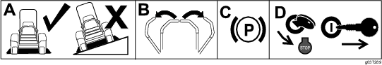
Park the machine on a level surface.
-
Move the motion-control levers to the NEUTRAL-LOCK position.
-
Engage the parking brake.
-
Shut off the engine and remove the key.
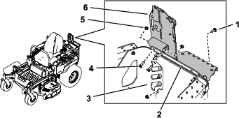
Assembling the Kit
Parts needed for this procedure:
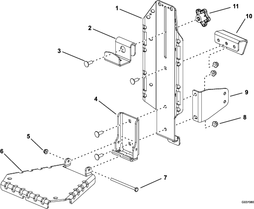
| Upper mount | 1 |
| Main bracket | 1 |
| Top bracket | 1 |
| Lower support bracket | 1 |
| Welded support bracket | 1 |
| Carriage bolt (5/16 x 7/8 inch) | 4 |
| Nut (5/16 inch) | 3 |
| Knob | 1 |
| Hinge bracket | 1 |
| Nut (1/4 inch) | 1 |
| Bolt (1/4 x 4-1/4 inches) | 1 |
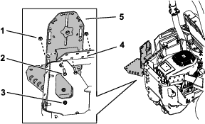
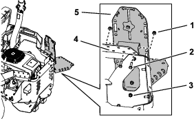
Assemble the kit as shown in Figure 2. Ensure to loosely install the upper mount to the main bracket; refer to Figure 3 to determine which hole to use in the upper mount.
Note: Do not overtighten the bolt (1/4 x 4-1/4 inches) and nut (1/4 inch); the hinge bracket must pivot freely.
Note: Install the lower support bracket only if you are mounting the kit in front of the rear tires. Install the bracket so that the large face is oriented rearward on the machine; Figure 2 shows the bracket orientation for mounting the kit on the left side of the machine.
For 2021 and newer machines, you cannot install the kit in front of the rear tire on the right side of the machine.
Mounting the Kit to the Machine
Parts needed for this procedure:
| Bolt (5/16 x 1 inch) | 3 |
| Nut (5/16 inch)—use only 4 for 2017 and older machines | 6 |
| Carriage bolt (5/16 x 7/8 inch)—use only 1 for 2017 and older machines | 4 |
| Inner support bracket—2018 and newer machines only | 1 |
| Left pod support bracket—2021 and newer machines only | 1 |
| Thread-forming screw (3/8 x 1 inch)—2021 and newer machines only | 2 |
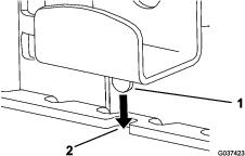
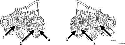
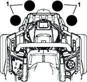
Mounting Locations
You can mount this kit in 6 locations on the machine (Figure 4). Refer to 1 of the following procedures to mount the kit in the desired location.
Note: For 1500 Series Titan HD machines, you can only mount the kit in the 2 locations in front of the rear tires.
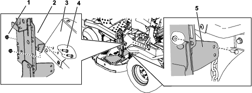
Mounting the Kit in Front of the Rear Tires
-
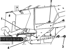
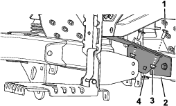
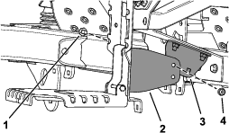
Secure the mount assembly to the console cover using 2 bolts (5/16 x 1 inch) and 2 nuts (5/16 inch) as shown in Figure 5 or Figure 6.
-
Tighten the fasteners securing the upper mount to the main bracket.
-
Secure the lower support bracket to the rear side of the bracket under the console cover using 1 bolt (5/16 x 1 inch) and 1 nut (5/16 inch) as shown in Figure 5 or Figure 6.
Note: You will not use the bottom hole in the main bracket or lower support bracket.
Note: Ensure that the assembly is vertical. If it hangs at an angle, the lower support bracket may be installed incorrectly.
Mounting the Kit in Front of the Rear Tires
-
For 2021 and newer machines only, do the following:
-
Remove the 2 torx-head screws (1/4 x 1-5/16 inches) and 2 locknuts (1/4 inch) from the left pod (Figure 7).
Retain the 2 torx-head screws (1/4 x 1-5/16 inches) and 2 locknuts (1/4 inch).
-
Secure the left pod support bracket using the 2 new thread-forming screws (3/8 x 1 inch) and the previously removed 2 torx-head screws (1/4 x 1-5/16 inches) and 2 locknuts (1/4 inch) as shown in Figure 8.
Note: Ensure that you install the left pod support bracket behind the left pod. Do not install the bracket between the pod and cladding piece.
-
-
Secure the mount assembly to the console cover using 2 bolts (5/16 x 1 inch) and 2 nuts (5/16 inch) as shown in Figure 5 or Figure 6.
-
Tighten the fasteners securing the upper mount to the main bracket.
-
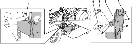
Secure the inner support bracket to the pod support bracket using 2 carriage bolts (5/16 x 7/8 inch) and 2 nuts (5/16 inch) as shown in Figure 9.
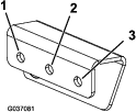
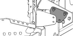
When installing the inner support bracket on the left side of the machine, orient the inner support bracket as shown in Figure 10.
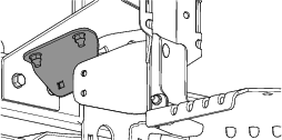
When installing the inner support bracket on the right side of the machine, orient the inner support bracket as shown in Figure 11.
-
Secure the lower support bracket to the inner support bracket under the console cover using 1 bolt (5/16 x 7/8 inch) and 1 nut (5/16 inch) as shown in Figure 12.
Note: You will not use the bottom hole in the main bracket or lower support bracket.
Note: Ensure that the assembly is vertical. If it hangs at an angle, the lower support bracket may be installed incorrectly.
Mounting the Kit to the Side of the Engine Guard
-
Secure the mount assembly to the side upper guard using 2 bolts (5/16 x 1 inch) and 2 nuts (5/16 inch) as shown in Figure 13 or Figure 14.
-
Tighten the fasteners securing the upper mount to the main bracket.
-
Secure the bottom of the main bracket to the engine guard using 1 carriage bolt (5/16 x 7/8 inch) and 1 nut (5/16 inch) as shown in Figure 13 or Figure 14.
Mounting the Kit to the Rear Engine Guard
-
Secure the mount assembly to the rear upper guard using 2 bolts (5/16 x 1 inch) and 2 nuts (5/16 inch) as shown in Figure 15 or Figure 16.
-
Tighten the fasteners securing the upper mount to the main bracket.
-
Secure the bottom of the main bracket to the rear engine guard using 1 carriage bolt (5/16 x 7/8 inch) and 1 nut (5/16 inch) as shown in Figure 15 or Figure 16.
Installing a Front-Weight Kit
Parts needed for this procedure:
| Front-weight kit (sold seperately) | 1 |
If 2 or more accessory-mount kits (i.e., bucket kit or universal mount kit) are added to any of the 4 locations shown in Figure 17, add a front-weight kit. Contact your Authorized Service Dealer for the front-weight kit.
Operation
Mounting Attachments
Use only Toro-approved attachments and accessories. The maximum capacity is 11.3 kg (25 lb).
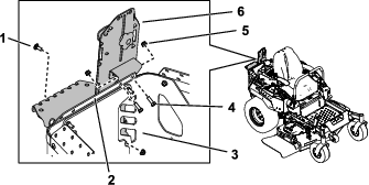
Use the top bracket and hinge bracket for mounting attachments or accessories; secure them using the holes in the mounting brackets.
Secure the hinge bracket when not in use; refer to Securing the Hinge Bracket.
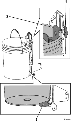
Mounting a Bucket
Note: If desired, you can remove the hinge bracket and mount the bucket using the welded support bracket.
-
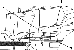
Loosen the knob and raise the top bracket. Tighten the knob to hold it in place (Figure 18).
-
If you removed the hinge bracket, place the bottom lip of the bucket over the bottom ledge of the welded support bracket (Figure 18).
-
Loosen the knob and lower the top bracket as far as possible over the rim of the bucket. Tighten the knob (Figure 18).
Securing the Hinge Bracket
-
Raise the hinge bracket.
-
Loosen the knob and lower the top bracket, inserting the tab into the notch in the hinge bracket (Figure 19).
-
Tighten the knob.