| Maintenance Service Interval | Maintenance Procedure |
|---|---|
| Before each use or daily |
|
Introduction
This rotary-blade, walk-behind lawn mower is intended to be used by residential homeowners or professional, hired operators. It is designed primarily for cutting grass on well-maintained lawns on residential or commercial properties. It is not designed for cutting brush or for agricultural uses.
Read this information carefully to learn how to operate and maintain your product properly and to avoid injury and product damage. You are responsible for operating the product properly and safely.
You may contact Toro directly at www.Toro.com for product and accessory information, help finding a dealer, or to register your product.
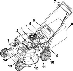
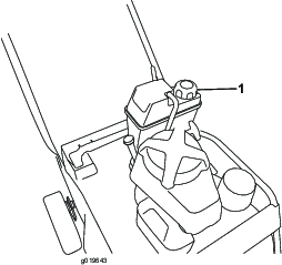
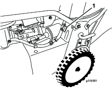
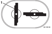
Whenever you need service, genuine Toro parts, or additional information, contact an Authorized Service Dealer or Toro Customer Service and have the model and serial numbers of your product ready. Figure 1 identifies the location of the model and serial numbers on the product. Write the numbers in the space provided.
This manual identifies potential hazards and has safety messages identified by the safety alert symbol (Figure 2), which signals a hazard that may cause serious injury or death if you do not follow the recommended precautions.

This manual uses 2 words to highlight information. Important calls attention to special mechanical information and Note emphasizes general information worthy of special attention.
It is a violation of California Public Resource Code Section 4442 or 4443 to use or operate the engine on any forest-covered, brush-covered, or grass-covered land unless the engine is equipped with a spark arrester, as defined in Section 4442, maintained in effective working order or the engine is constructed, equipped, and maintained for the prevention of fire.
This spark ignition system complies with Canadian ICES-002.
The enclosed Engine Owner’s Manual is supplied for information regarding the US Environmental Protection Agency (EPA) and the California Emission Control Regulation of emission systems, maintenance, and warranty. Replacements may be ordered through the engine manufacturer.
Net Torque: The gross or net torque of this engine was laboratory rated by the engine manufacturer in accordance with the Society of Automotive Engineers (SAE) J1940. As configured to meet safety, emission, and operating requirements, the actual engine torque on this class of mower will be significantly lower. Go to www.Toro.com to view specifications on your mower model.
Warning
CALIFORNIA
Proposition 65 Warning
The engine exhaust from this product contains chemicals known to the State of California to cause cancer, birth defects, or other reproductive harm.
Safety
This machine has been designed in accordance with ANSI B71.1-2012.
General Safety
This product is capable of amputating hands and feet and of throwing objects. Always follow all safety instructions to avoid serious personal injury.
Using this product for purposes other than its intended use could prove dangerous to you and bystanders.
-
Read and understand the contents of this Operator’s Manual before you start the engine. Ensure that everyone using this product knows how to use it and understands the warnings.
-
Do not put your hands or feet near moving components of the machine.
-
Do not operate the machine without all guards and other safety protective devices in place and working on the machine.
-
Keep clear of any discharge opening. Keep bystanders a safe distance from the machine.
-
Keep children out of the operating area. Never allow children to operate the machine.
-
Stop the machine and shut off the engine before servicing, fueling, or unclogging the machine.
Improperly using or maintaining this machine can result in injury. To reduce the potential for injury, comply with these safety instructions and always pay attention to the safety-alert symbol, which means Caution, Warning, or Danger—personal safety instruction. Failure to comply with these instructions may result in personal injury or death.
You can find additional items of safety information in their respective sections throughout this manual.
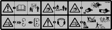
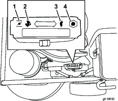
Safety and Instructional Decals
Safety decals and instructions are easily visible to the operator and are located near any area of potential danger. Replace any decal that is damaged or lost.


Setup
Installing the Handle
Warning
Folding or unfolding the handle improperly can damage the cables, causing an unsafe operating condition.
-
Do not damage the cables when folding or unfolding the handle.
-
If a cable is damaged, contact an Authorized Service Dealer.
-
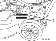
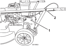
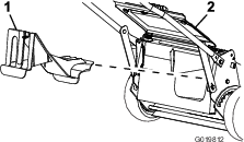
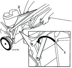
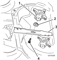
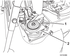
Remove the 2 bolts from the machine frame in the location shown in Figure 3.
-
Rotate the handle rearward to the operating position.
-
Secure the handle to the machine with the bolts that you removed in step 1
-
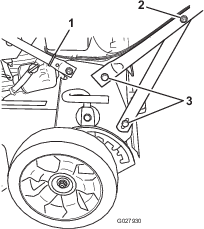
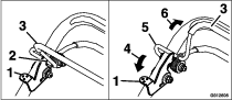
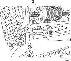
Tighten the fasteners that support the handle on both sides of the machine as shown in Figure 4.
-
Use a cable tie to secure the cables to the lower handle in the location shown in Figure 4.
-
Secure the cable tie on the handle and trim off the excess material from the tie.
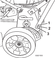
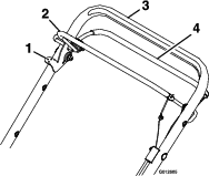
Adjusting the Handle Height
-
Stand in the operating position to determine the most comfortable handle height.
-
Remove the handle bolt and insert it in 1 of the 3 holes located at the bottom of the handle bracket (Figure 5).
-
Tighten the handle bolt until it is snug.
-
Repeat the steps above for the other side of the machine.
Filling the Crankcase with Oil
Important: This machine does not come with oil in the engine. Before starting the engine, fill the engine with oil.
-
Move the machine to a level surface.
-
Remove the dipstick by rotating the cap counterclockwise and pulling it out.
-
If the crankcase is empty, add about 3/4 of the crankcase capacity of oil into the oil-fill tube (Figure 6).
Note: Max. fill: 0.85 L (29 oz) with oil filter; 0.65 L (22 oz) without oil filter; type: SAE 30 or SAE 10W30 weight detergent oil with an API service classification of SF, SG, SH, SJ, SL, or higher.
-
Wipe the dipstick clean with a clean cloth.
-
Insert the dipstick into the filler neck, then remove it.
Note: To ensure an accurate oil level reading, install the dipstick fully.
-
Read the oil level on the dipstick (Figure 6).
-
If the oil level is below the Add mark, add a small amount of oil slowly to the oil-fill tube, then repeat steps 4 through 6 until the oil level is at the Full mark on the dipstick.
-
If the oil level above the Full mark, drain the excess oil until the oil level is at the Full mark on the dipstick; refer to Changing the Engine Oil.
Important: If the oil level in the crankcase is too low or too high and you run the engine, you may damage the engine.
-
-
Insert the dipstick into the filler neck and rotate the cap clockwise until it is tight.
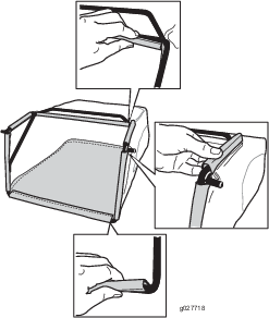
Assembling the Grass Bag
Product Overview
Operation
Before Operation
Before Operation Safety
General Safety
-
Become familiar with the safe operation of the equipment, operator controls, and safety signs.
-
Check that all guards and safety devices, such as deflectors and/or grass catcher, are in place and working properly.
-
Always inspect the machine to ensure that the blades, blade bolts, and cutting assembly are not worn or damaged.
-
Inspect the area where you will use the machine and remove all objects that the machine could throw.
-
Adjusting the cutting height may bring you into contact with the moving blade, causing serious injury.
-
Shut off the engine and wait for all moving parts to stop.
-
Do not put your fingers under the housing when adjusting the cutting height.
-
Fuel Safety
Danger
Fuel is extremely flammable and highly explosive. A fire or explosion from fuel can burn you and others and can damage property.
-
To prevent a static charge from igniting the fuel, place the container and/or machine directly on the ground before filling, not in a vehicle or on an object.
-
Fill the fuel tank outdoors, in an open area, when the engine is cold. Wipe up any fuel that spills.
-
Do not handle fuel when smoking or around an open flame or sparks.
-
Store fuel in an approved container and keep it out of the reach of children.
Warning
Fuel is harmful or fatal if swallowed. Long-term exposure to vapors can cause serious injury and illness.
-
Avoid prolonged breathing of vapors.
-
Keep your hands and face away from the nozzle and the fuel-tank opening.
-
Keep fuel away from your eyes and skin.
Checking the Engine-Oil Level
Before each use, ensure that the oil level is between the Add and Full marks on the dipstick (Figure 13).
-
Move the machine to a level surface.
-
Clean around the dipstick (Figure 13).
-
Remove the dipstick by rotating the cap counterclockwise and pulling it out.
-
Wipe the dipstick clean with a clean cloth.
-
Insert the dipstick into the filler neck, then remove it.
Note: To ensure an accurate oil level reading, install the dipstick fully.
-
Read the oil level on the dipstick (Figure 13).
-
If the oil level is below the Add mark, add a small amount of oil slowly to the oil-fill tube, then repeat steps 4 through 6 until the oil level is at the Full mark on the dipstick.
-
If the oil level above the Full mark, drain the excess oil until the oil level is at the Full mark on the dipstick; refer to Changing the Engine Oil.
Important: If the oil level in the crankcase is too low or too high and you run the engine, you may damage the engine.
-
-
Insert the dipstick into the filler neck and rotate the cap clockwise until it is tight.
Filling the Fuel Tank
-
For best results, use only clean, fresh (less than 30 days old), unleaded gasoline with an octane rating of 87 or higher ((R+M)/2 rating method).
-
Oxygenated fuel with up to 10% ethanol or 15% MTBE by volume is acceptable.
-
Ethanol: Gasoline with up to 10% ethanol (gasohol) or 15% MTBE (methyl tertiary butyl ether) by volume is acceptable. Ethanol and MTBE are not the same. Gasoline with 15% ethanol (E15) by volume is not approved for use. Never use gasoline that contains more than 10% ethanol by volume, such as E15 (contains 15% ethanol), E20 (contains 20% ethanol), or E85 (contains up to 85% ethanol). Using unapproved gasoline may cause performance problems and/or engine damage which may not be covered under warranty.
-
Do not use gasoline containing methanol.
-
Do not store fuel either in the fuel tank or in fuel containers over the winter unless a fuel stabilizer is used.
-
Do not add oil to gasoline.
Fill the fuel tank with fresh unleaded regular gasoline from a major name-brand service station (Figure 14).
Important: To reduce starting problems, add fuel stabilizer to the fuel all season, mixing it with gasoline less than 30 days old.
Note: The capacity of the fuel tank is 3.76 L (0.99 US gallon).
Adjusting the Cutting Height
The cutting heights range from 38 mm (1-1/2 inches) to 127 mm (5 inches) in 13 mm (1/2 inch) increments.
The cutting height is controlled with a front lever and a rear lever, both on the left side of the machine (Figure 16 and Figure 17). To raise or lower the machine, engage the lever, raise or lower the machine, and then disengage the lever.
Checking the Blade-Stop System Operation
Before each use, check that the blades stop within 3 seconds of releasing the control bar.
Using the Grass Bag
| Maintenance Service Interval | Maintenance Procedure |
|---|---|
| Before each use or daily |
|
You can use the grass bag to check the blade-stop system.
-
Remove the rear-discharge plug.
-
Install the empty grass bag on the machine.
-
Start the engine.
-
Engage the blades.
Note: The bag should begin to inflate, indicating that the blades are rotating.
-
While watching the bag, release the control bar.
Note: If the bag does not deflate within 3 seconds of releasing the control bar, the blade-stop system may be deteriorating and, if ignored, could result in an unsafe operating condition. Have the machine inspected and serviced by an Authorized Service Dealer.
-
Stop the engine and wait for all moving parts to stop.
Not Using the Grass Bag
-
Move the machine onto a paved surface in a non-windy area.
-
Set all 4 wheels to the 3-1/2 inch (89 mm) cutting height setting.
-
Take a half sheet of newspaper and crumple it into a ball small enough to go under the machine (about 3 inches or 75 mm in diameter).
-
Place the newspaper ball about 5 inches (13 cm) in front of the machine.
-
Start the engine.
-
Engage the blades.
-
Release the control bar and begin counting out 3 seconds.
-
On the count of 3, push the machine quickly forward over the newspaper.
-
Stop the engine and wait for all moving parts to stop.
-
Go to the front of the machine and check the newspaper ball.
Note: If the newspaper ball did not go under the machine, repeat steps 4 through 10.
Important: If the newspaper is unravelled or shredded, the blades did not stop properly, which could result in an unsafe operating condition. Contact an Authorized Service Dealer.
During Operation
During Operating Safety
General Safety
-
Wear appropriate clothing, including eye protection; slip-resistant, substantial footwear; and hearing protection. Tie back long hair, secure loose clothing, and do not wear jewelry.
-
Do not operate the machine while ill, tired, or under the influence of alcohol or drugs.
-
The blade is sharp; contacting the blade can result in serious personal injury. Shut off the engine and wait for all moving parts to stop before leaving the operating position.
-
When you release the blade-control bar, the engine should shut off and the blade should stop within 3 seconds. If not, stop using your machine immediately and contact an Authorized Service Dealer.
-
Operate the machine only in good visibility and appropriate weather conditions. Do not operate the machine when there is the risk of lighting.
-
Wet grass or leaves can cause serious injury if you slip and contact the blade. Mow only in dry conditions.
-
Use extreme care when approaching blind corners, shrubs, trees, or other objects that may block your view.
-
Watch for holes, ruts, bumps, rocks, or other hidden objects. Uneven terrain could cause a slip-and-fall accident.
-
Stop the machine and inspect the blades after striking an object or if there is an abnormal vibration in the machine. Make all necessary repairs before resuming operation.
-
Before leaving the operating position, shut off the engine, remove the key, and wait for all moving parts to stop.
-
If the engine has been running the muffler will be hot and can severely burn you. Keep away from the hot muffler.
-
Check the grass catcher components and the discharge guard frequently and replace them with the manufacturer’s recommended parts when necessary.
-
Use accessories and attachments approved by the The Toro® Company only.
Slope Safety
-
Mow across the face of slopes; never up and down. Use extreme caution when changing direction on slopes.
-
Do not mow on excessively steep slopes. Poor footing could cause a slip-and-fall accident.
-
Do not mow near drop-offs, ditches, or embankments. You could lose your footing or balance.
Starting the Engine
-
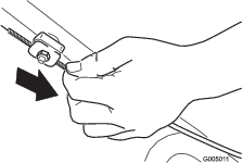
Connect the wire to the spark plug (Figure 9).
-
Open the fuel shut-off valve (Figure 18).
Note: When the fuel shut-off valve is open, the lever is parallel with the fuel line.
-
Move the throttle control to the Choke position (Figure 11).
-
Pull the starter handle lightly until you feel resistance, then pull it sharply.
-
Move the throttle control lever to the Fast position when the engine starts (Figure 10).
Note: If the engine fails to start after 3 pulls, repeat steps 3 through 5.
Stopping the Engine
-
Move the throttle control to the Off position and wait for all moving parts to stop.
-
Close the fuel shut-off valve and disconnect the wire from the spark plug if you do not use the machine or leave it unattended.
Operating the Self-Propel Drive and Engaging the Cutting Blades
To operate the self-propel drive, hold the drive bail against the handle (Figure 19).
To engage the cutting blades, do the following:
-
Push and hold the blade control lock lever forward to release the blade control bail (Figure 20).
-
Squeeze the blade control bail against the handle and release the blade control lock lever; the blade should engage.
-
Release the blade control bail to disengage the blade. The blade control lock lever will reset to lock the blade control bail.
Recycling the Clippings
This machine comes from the factory ready to recycle grass and leaf clippings back into the lawn. To prepare the machine to recycle:
-
If the side-discharge chute is on the machine, remove it and install the side-discharge deflector; refer to Removing the Side-Discharge Chute.
-
If the grass bag is on the machine, remove it; refer to Removing the Grass Bag.
-
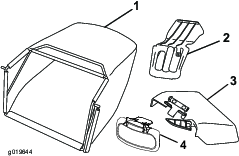
If the rear-discharge plug is not installed, grip it by the handle, raise the rear deflector, and insert it into the rear-discharge chute until the latch locks into place; refer to Figure 21.
Bagging the Clippings
Use the grass bag when you want to collect grass and leaf clippings from the lawn.
If the side-discharge chute is on the machine, remove it and install the side-discharge deflector before bagging the clippings; refer to Installing the Side-Discharge Chute.
Installing the Grass Bag
-
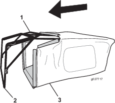
Raise and hold up the rear deflector (Figure 22).
-
Remove the rear-discharge plug by pulling down on the latch with your thumb and pulling the plug out from the machine (Figure 21).
-
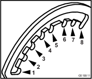
Install the bag rod into the notches at the base of the handle, and rock the bag back and forth to ensure that the rod is seated at the bottom of both notches; refer to Figure 22.
-
Lower the rear deflector until it rests on the grass bag.
Removing the Grass Bag
To remove the bag, reverse the steps in Installing the Grass Bag above.
Side-Discharging the Clippings
Use the side discharge for cutting very tall grass.
Installing the Side-Discharge Chute
Important: Ensure that the rear-discharge plug is in place before you recycle the clippings.
-
Stop the engine and wait for all moving parts to stop.
-
Remove the grass bag if it is installed on the machine; refer to Removing the Grass Bag.
-
Insert the rear-discharge plug; refer to Bagging the Clippings.
-
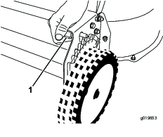
Remove the side-discharge deflector by pulling up on the spring that holds the deflector in place and removing the deflector (Figure 23).
-
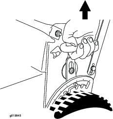
Install the side-discharge chute (Figure 24) by pulling up on the spring, placing the chute over the opening, and lowering the spring over the tabs on top of the discharge chute.
Removing the Side-Discharge Chute
To remove the side-discharge chute, reverse the steps in Installing the Side-discharge Chute.
Operating Tips
General Tips
-
Review the safety instructions and read this manual carefully before operating the machine.
-
Clear the area of sticks, stones, wire, branches, and other debris that the blades could hit and throw.
-
Keep everyone, especially children and pets, away from the area of operation.
-
Avoid striking trees, walls, curbs, or other solid objects. Never deliberately mow over any object.
-
If the machine strikes an object or starts to vibrate, immediately stop the engine, disconnect the wire from the spark plug, and examine the machine for damage.
-
Maintain sharp blades throughout the cutting season. Periodically file down nicks on the blades.
-
Replace the blades when necessary with original Toro replacement blades.
-
Mow only dry grass or leaves. Wet grass and leaves tend to clump on the yard and can cause the machine to plug or the engine to stall.
-
Clean the under the machine after each mowing. Refer to Cleaning under the Machine.
-
Keep the engine in good running condition.
-
Set the engine speed to the fastest position for the best cutting results.
-
Clean the air filter frequently. Mulching stirs up more clippings and dust which clogs the air filter and reduces engine performance.
Cutting Grass
-
Grass grows at different rates at different times of the year. In the summer heat, it is best to cut grass at the 51 mm (2 inch), 64 mm (2-1/2 inch), or 83 mm (3 inch) cutting-height settings. Cut only about a third of the grass blade at a time. Do not cut below the 51 mm (2 inch) setting unless the grass is sparse or it is late fall when grass growth begins to slow down.
-
When cutting grass over 15 cm (6 inches) tall, first mow at the highest cutting height setting and walk slower; then mow again at a lower setting for the best lawn appearance. If the grass is too long and the leaves clump on top of the lawn, the machine may plug and cause the engine to stall.
-
Alternate the mowing direction. This helps disperse the clippings over the lawn for even fertilization.
If the finished lawn appearance is unsatisfactory, try 1 or more of the following:
-
Sharpen the blades.
-
Walk at a slower pace while mowing.
-
Raise the cutting height on your machine.
-
Cut the grass more frequently.
-
Overlap cutting swaths instead of cutting a full swath with each pass.
-
Set the cutting height on the front wheels a notch lower than the rear wheels. For example, set the front wheels at 51 mm (2 inches) and the rear wheels at 64 mm (2-1/2 inches).
Cutting Leaves
-
After cutting the lawn, ensure that half of the lawn shows through the cut leaf cover. You may need to make more than a single pass over the leaves.
-
For light leaf coverage, set all the wheels at the same cutting height setting.
-
If there are more than 12.7 cm (5 inches) of leaves on the lawn, set the front cutting height 1 or 2 notches higher than the rear cutting height. This makes it easier to feed the leaves under the machine deck.
-
Slow down your mowing speed if the machine does not cut the leaves finely enough.
After Operation
After Operating Safety
General Safety
-
Clean grass and debris from the machine to help prevent fires. Clean up oil or fuel spills.
-
Allow the engine to cool before storing the machine in any enclosure.
-
Never store the machine or fuel container where there is an open flame, spark, or pilot light, such as on a water heater or on other appliances.
Hauling Safety
-
Use care when loading or unloading the machine into a trailer or truck.
-
Use full-width ramps for loading the machine into a trailer or truck. Do not exceed a 15° angle between the ramp and the trailer or truck.
-
Tie the machine down securely using straps, chains, cable, or ropes. Both front and rear straps should be directed down and outward from the machine.
Cleaning under the Machine
For optimal cutting performance, keep the underside of the machine clean. You may either wash or scrape the clippings away from under the machine.
Washing under the Machine
| Maintenance Service Interval | Maintenance Procedure |
|---|---|
| Before each use or daily |
|
-
Position the machine on a flat concrete or asphalt surface near a garden hose.
-
Start the engine.
-
Hold the running garden hose at handle level and direct the water to flow on the ground just in front of the right rear tire (Figure 25).

Note: The blades will draw in water and wash out clippings. Let the water run until you no longer see clippings being washed out from under the housing.
-
Stop the engine and wait for all moving parts to stop.
-
Turn off the water.
-
Start the machine and let it run for a few minutes to dry out the moisture on the machine and its components.
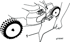
Scraping under the Machine
If washing does not remove all debris from under the machine, scrape it clean.
-
Disconnect the wire from the spark plug.
-
Drain the fuel from the fuel tank; refer to Emptying the Fuel Tank and Cleaning the Filter.
-
Tip the machine onto its side, with the air filter up in the air, until the upper handle rests on the ground.
-
Remove the dirt and grass clippings with a hardwood scraper; avoid burrs and sharp edges.
-
Turn the machine upright.
-
Fill the fuel tank.
-
Connect the wire to the spark plug.
Maintenance
Recommended Maintenance Schedule(s)
| Maintenance Service Interval | Maintenance Procedure |
|---|---|
| After the first 5 hours |
|
| Before each use or daily |
|
| Every 25 hours |
|
| Every 50 hours |
|
| Every 100 hours |
|
| Every 250 hours |
|
| Every 300 hours |
|
| Yearly or before storage |
|
Important: Refer to your engine owner’s manual for additional maintenance procedures.
Maintenance Safety
-
Disconnect the spark-plug wire from the spark plug before performing any maintenance procedure.
-
Wear gloves and eye protection when servicing the machine.
-
The blade is sharp; contacting the blade can result in serious personal injury. Wear gloves when servicing the blade.
-
Never tamper with safety devices. Check their proper operation regularly.
-
Tipping the machine may cause the fuel to leak. Fuel is flammable and explosive, and can cause personal injury. Run the engine dry to remove the fuel with a hand pump; never siphon the fuel.
Servicing the Air Filter
| Maintenance Service Interval | Maintenance Procedure |
|---|---|
| Before each use or daily |
|
| Every 25 hours |
|
| Every 300 hours |
|
Important: Do not operate the engine without the air filter assembly; extreme engine damage will occur.
-
Stop the engine and wait for all moving parts to stop.
-
Disconnect the wire from the spark plug.
-
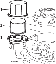
Remove the cover and clean it thoroughly (Figure 26).
-
Remove the foam pre-filter and paper filter (Figure 26).
-
Remove the foam pre-filter from the paper filter (Figure 26), and replace the paper filter if it is excessively dirty.
Important: Do not try to clean a paper filter.
-
Wash the foam pre-cleaner with a mild detergent and water, then blot it dry.
Note: Do not add oil to the foam pre-cleaner.
-
Install the foam pre-cleaner onto the paper filter.
-
Install the air-filter assembly.
-
Install the cover.
Changing the Engine Oil
| Maintenance Service Interval | Maintenance Procedure |
|---|---|
| After the first 5 hours |
|
| Every 50 hours |
|
-
Run the engine to warm the engine oil.
Note: Warm oil flows better and carries more contaminants.
Warning
Oil may be hot after engine has been run, and contact with hot oil can cause severe personal injury.
Avoid contacting the hot engine oil when you drain it.
-
Stop the engine and wait for all moving parts to stop.
-
Disconnect the wire from the spark plug.
-
Place a suitable drain pan under the right side of the machine.
-
Remove the dipstick by rotating the cap counterclockwise and pulling it out.
-
Tip the machine, with the air filter up, to drain the oil into the drain pan (Figure 26).
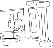
Note: You can also remove the oil from the crankcase using an oil extractor.
-
Return the machine to the operating position.
-
Insert the dipstick into the filler neck and rotate the cap clockwise until it is tight.
-
Recycle the used oil according to local codes.
-
Fill the crankcase to the Full line on the dipstick with fresh oil. Refer to Filling the Crankcase with Oil.
-
Wipe up any spilled oil.
Changing the Oil Filter
| Maintenance Service Interval | Maintenance Procedure |
|---|---|
| Every 100 hours |
|
-
Run the engine to warm the oil.
-
Stop the engine and wait for all moving parts to stop.
-
Disconnect the wire from the spark plug.
-
Drain the engine oil; refer to Changing the Engine Oil.
-
Place a rag under the oil filter to catch any oil that may leak out as you remove the filter.
-
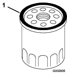
Remove the oil filter (Figure 28).
-
Use your finger to coat the gasket on the new filter with oil (Figure 29).
-
Install the new filter until the gasket contacts the filter base, then hand tighten the filter an additional 2/3 turn.
-
Fill the crankcase to the Full line on the dipstick with fresh oil; refer to Filling the Crankcase with Oil.
-
Connect the wire to the spark plug.
-
Run the engine for about 3 minutes.
-
Stop the engine, wait for all moving parts to stop, and check for oil leakage around the filter.
-
Add oil to compensate for the oil in the oil filter; refer to Checking the Engine-Oil Level
-
Recycle the used oil filter according to local codes.
Servicing the Spark Plug
| Maintenance Service Interval | Maintenance Procedure |
|---|---|
| Every 100 hours |
|
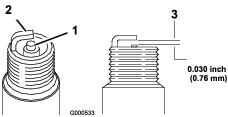
Use an NGK BPR5ES spark plug or equivalent.
-
Stop the engine and wait for all moving parts to stop.
-
Disconnect the wire from the spark plug.
-
Clean around the spark plug.
-
Remove the spark plug from the cylinder head.
Important: Replace a cracked, fouled, or dirty spark plug. Do not clean the electrodes because grit entering the cylinder can damage the engine.
-
Set the gap on the plug to 0.76 mm (0.030 inch); refer to Figure 30.
-
Install the spark plug and the gasket seal.
-
Torque the plug to 17 ft-lb (23 N-m).
-
Connect the wire to the spark plug.
Checking the Condition of the Belts
| Maintenance Service Interval | Maintenance Procedure |
|---|---|
| Every 50 hours |
|
-
Stop the engine and wait for all moving parts to stop.
-
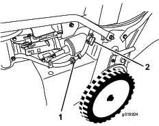
Remove the belt cover (Figure 9) by removing the 4 bolts that hold it to the machine housing.
-
Check the belts for any cracks, frayed edges, burn marks, or any other damage.
-
Replace all damaged belts.
-
If you replace the blade-drive belt, you must adjust it. Refer to Servicing the Blade-Drive System.
-
Install the belt cover with the 4 bolts that you removed in step 2.
Emptying the Fuel Tank and Cleaning the Filter
| Maintenance Service Interval | Maintenance Procedure |
|---|---|
| Every 50 hours |
|
| Every 100 hours |
|
| Yearly or before storage |
|
Note: The fuel tank filter (screen) element is located inside the fuel tank at the outlet. This filter is a part of the fuel tank and cannot be removed.
-
Stop the engine and wait for it to cool down.
Important: Drain gasoline from a cold engine only.
-
Disconnect the wire from the spark plug.
-
Close the fuel shut-off valve.
-
Disconnect the fuel line by loosening the tube clamp at the carburetor.
-
Open the fuel shut-off valve and drain the gasoline completely from the tank and fuel line into an approved fuel container.
-
Remove the fuel tank from the machine.
-
Pour a small amount of fuel in the fuel tank, move the fuel around in the tank, and pour it out into an approved fuel container.
-
Install the fuel tank and the fuel line.
Changing the Fuel Filter
| Maintenance Service Interval | Maintenance Procedure |
|---|---|
| Every 100 hours |
|
-
Stop the engine and wait for all moving parts to stop.
-
Disconnect the wire from the spark plug.
-
Close the fuel shut-off valve (Figure 31).
-
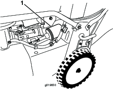
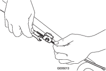
Remove the fuel filter (Figure 31) from the fuel line by loosening the tube clamps surrounding the fuel filter.
-
Install a new fuel filter in the fuel line using the tube clamps that you removed in step 4.
Servicing the Blade-Drive System
| Maintenance Service Interval | Maintenance Procedure |
|---|---|
| After the first 5 hours |
|
| Every 50 hours |
|
-
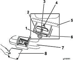
Loosen the 2 screws on the belt-cover-access panel and remove the panel (Figure 32).
-
Brush or blow out debris from the inside of the belt cover and around all the parts.
-
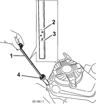
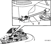
Hold a feeler gauge set between 0.005 and 0.03 inches (0.13 and 0.76 mm) against the wall and slide it down behind the belt tension spring; refer to Figure 33.
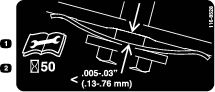
Note: If there is a visible gap between the gauge and the spring, tighten the adjusting bolt and the nut until the feeler gauge barely slides freely in and out of the gap (Figure 32).
Important: Do not overtighten the adjusting bolt. This could damage the blade-drive belt.
-
Install the belt-cover-access panel.
Servicing the Cutting Blades
| Maintenance Service Interval | Maintenance Procedure |
|---|---|
| Before each use or daily |
|
Important: You will need a torque wrench to install the blades properly. If you do not have a torque wrench or are uncomfortable performing this procedure, contact an Authorized Service Dealer.
Examine the blades for sharpness and any wear or damage whenever you run out of gasoline; refer to Inspecting the Blades. If the blade edge is dull or nicked, have it sharpened or replace it. If the blades are worn, bent, damaged or cracked, replace them immediately with a genuine Toro replacement blades.
Danger
A worn or damaged blade can break, and a piece of the blade could be thrown toward the operator or a bystander, resulting in serious personal injury or death.
-
Inspect the blades periodically for wear or damage.
-
Replace worn or damaged blades.
Note: Maintain sharp blades throughout the cutting season, because sharp blades cut cleanly without tearing or shredding the grass blades. Tearing and shredding turns grass brown at the edges, which slows growth and increases the chance of disease.
Preparing to Service the Cutting Blades
Tip the machine onto its side, with the air filter up in the air, until the upper handle rests on the ground.
Warning
The blades are sharp; contacting a blade could result in serious personal injury.
-
Disconnect the wire from the spark plug.
-
Wear gloves when servicing the blades.
Inspecting the Blades
| Maintenance Service Interval | Maintenance Procedure |
|---|---|
| Before each use or daily |
|
-
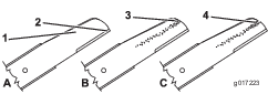
Inspect the cutting edges (Figure 34). If the edges are not sharp or have nicks, remove the blades and have them sharpened or replace them.
-
Inspect the blades themselves, especially the curved area (Figure 42). If you notice any damage, wear, or a slot forming in this area (Figure 34), immediately replace them with new blades.
Danger
If you allow a blade to wear, a slot will form between the sail and flat part of the blade. Eventually a piece of the blade may break off and be thrown from under the housing, possibly resulting in serious injury to you or bystanders.
-
Inspect the blades periodically for wear or damage.
-
Never try to straighten a blade that is bent or weld a broken or cracked blade.
-
Check for bent blades; refer to Checking for Bent Blades.
-
Checking for Bent Blades
-
Rotate the blades until they are positioned as shown in Figure 35.
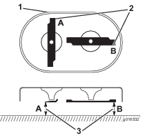
-
Measure from a level surface to the cutting edges at locations A and B, (Figure 35), and record both dimensions.
-
Rotate the blades so that their opposite ends are at locations A and B.
-
Repeat the measurements in step 2 and record them.
Note: If the difference between the dimensions A and B obtained in steps 2 and 4 exceeds 1/8 inch, replace the blades; refer to Removing the Blades and Installing the Blades.
Warning
A blade that is bent or damaged could break apart and could seriously injure or kill you or bystanders.
-
Always replace a bent or damaged blade with a new blade.
-
Never file or create sharp notches in the edges or surfaces of a blade.
-
Removing the Blades
Replace the blades when they strike a solid object, are out of balance, bent, or worn. Use only genuine Toro replacement blades.
Installing the Blades
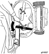
-
Install the first blade so that it is horizontal, along with all mounting hardware as shown in Figure 37.
Note: Tighten the bolt with your fingers.
Important: Position the curved ends of the blades to point toward the machine housing. Be sure to nest the raised areas on each blade driver with the recesses in the head of its corresponding spindle, and the pins on the other side of each blade driver with the holes in its corresponding blade.
-
Steady each blade with a board and turn the blade bolt clockwise with a torque wrench as shown in Figure 38; torque each blade bolt to 82 N-m (60 ft-lb).
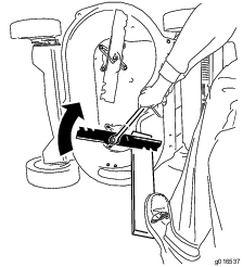
Important: A bolt torqued to 82 N-m (60 ft-lb) is very tight. Put your weight behind the wrench and tighten the bolt securely. This bolt is very difficult to overtighten.
-
Rotate the installed blade 1/4 turn until it is vertical, and install the other blade in the same manner as the first (refer to step 1).
Note: The blades should be perpendicular, forming an inverted “T” as shown in Figure 39.
-
Tighten the second blade; refer to step 2.
-
Rotate the blades by hand a full 360° turn to ensure that they do not touch.
Note: If the blades touch each other, they are not mounted correctly. Repeat steps 1 through 3 until the blades no longer touch each other.
Warning
Incorrectly installing the blades could damage the machine or cause an injury to the operator or to bystanders.
Changing the Blade-Brake-Clutch (BBC) Belt
| Maintenance Service Interval | Maintenance Procedure |
|---|---|
| Every 250 hours |
|
-
Stop the engine and wait for all moving parts to stop.
-
Disconnect the wire from the spark plug.
-
Remove the 4 bolts that hold the belt cover to the machine housing.
Note: Save the bolts for installing the belt cover to the machine housing.
-
Remove the belt cover.
-
Remove any debris from under the belt cover.
-
Remove the BBC belt guard (Figure 40).
Note: Save the mounting hardware for installing the BBC belt guard later.
-
Remove the BBC belt from the brake-drum pulley.
-
Move the tab forward (Figure 41).
Note: The tab prevents the transmission from tipping to the point where the transmission belt comes off.
-
Remove the transmission tension spring.
-
Remove the transmission belt from the transmission pulley.
-
Remove the BBC belt.
Note: Hold one of the blades using a glove or a rag and turn the blade spindle to help remove the BBC belt.
-
To install a new BBC belt, reverse the steps above.
-
Adjust the BBC cable; refer to Adjusting the Blade-Brake Cable.
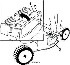
Adjusting the Self-Propel Cable
If the machine does not self-propel or tends to creep forward when you release the control bar, adjust the drive cable.
-
Stop the engine and wait for all moving parts to stop.
-
Loosen the cable support nut (Figure 42).
-
Pull down the cable jacket (toward the mower) until there is no slack in the cable (Figure 43).
-
Tighten the nut on the cable support.
-
Check the operation for desired drive control.
Note: If the unit creeps forward without the bail engaged or if the wheels spin when you lift the rear wheels off the ground, the cable is too tight; repeat steps1 and 2.
Note: Adjustment to obtain desired ground speed at full bail travel may be made in order to accommodate slower speeds.
Adjusting the Blade-Brake Cable
Adjust the blade-brake cable whenever you install a new cable or replace the BBC belt.
-
Stop the engine and wait for all moving parts to stop.
-
Disconnect the wire from the spark plug.
-
Remove the belt cover (Figure 9) by removing the 4 bolts that hold it to the machine housing.
Note: Save the bolts for installing the belt cover to the machine housing.
-
Remove any debris from under the belt cover.
-
Loosen the cable-clamp screw (Figure 44).
-
Pull the cable jacket until there is approximately 1/8 inch (3 mm) of slack.
Note: Do not put tension on the spring.
-
Tighten the cable-clamp screw to lock the adjustment in place.
-
Install the belt cover with the 4 bolts that you removed in step 3.
-
Connect the wire to the spark plug.
-
Check the operation of the blade-brake clutch; refer to Checking the Blade-Stop System Operation.
Changing the Blade-Drive Belt
Change the blade-drive belt as needed.
-
Stop the engine and wait for all moving parts to stop.
-
Disconnect the wire from the spark plug.
-
Remove the belt cover (Figure 9) by removing the 4 bolts that hold it to the machine housing.
Note: Save the bolts for installing the belt cover to the machine housing.
-
Remove any debris from under the belt cover.
-
Remove the BBC belt guard and the mounting hardware.
Note: Save the BBC belt guard and hardware for installation later.
-
Remove the BBC belt from the front left-hand pulley.
-
Loosen the adjusting bolt (Figure 32).
-
Remove the fixed idler pulley and the hardware (Figure 46).
Note: Save the idler pulley and hardware for installation later.
-
Remove the blade-drive belt.
-
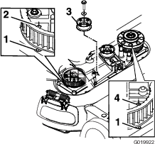
Align the holes in the right-hand and left-hand sprockets with the holes in the housing as shown in Figure 46.
Note: Hold the sprockets in place with a rod or a screwdriver.
-
When you have locked the sprockets in place, install the blade-drive belt and the fixed idler pulley.
Note: Ensure that the teeth are engaged in the sprockets.
-
Tighten the belt tension to the recommended settings; refer to Servicing the Blade-Drive System.
-
Remove the rod or screwdriver from the sprockets.
-
Ensure that the blades under the housing are properly aligned; refer to Servicing the Cutting Blades.
-
Install the BBC belt and the BBC belt guard and hardware.
-
Install the belt cover using the 4 bolts that you removed in step 3.
-
Connect the wire to the spark plug.
-
Check the operation of the control bar and the blade-brake clutch.
Storage
Store the machine in a cool, clean, dry place. Cover the machine to keep it clean and protected.
General Information
Store the machine in a cool, clean, dry place. Cover the machine to keep it clean and protected.
-
Perform the recommended annual maintenance procedures; refer to .
-
Clean under the machine; refer to Cleaning under the Machine.
-
Remove chaff, dirt, and grime from the external parts of the engine, the shrouding, and the top of the machine.
-
Check the condition of the blades; refer to Inspecting the Blades.
-
Service the air filter; refer to Servicing the Air Filter (page 16).
-
Tighten all nuts, bolts, and screws.
-
Touch up all rusted or chipped paint surfaces with paint available from an Authorized Service Dealer.
Preparing the Fuel System
Warning
Gasoline can vaporize if you store it over long periods of time and explode if it comes into contact with an open flame.
-
Do not store gasoline over long periods of time.
-
Do not store the machine with gasoline in the fuel tank or the carburetor in an enclosure with an open flame. (For example, a furnace or a water heater pilot light.)
-
Allow the engine to cool before storing it in any enclosure.
On the last refueling of the year, add fuel stabilizer to the fuel as directed by the engine manufacturer. Empty the fuel tank when mowing the last time before storing the machine.
-
Run the machine until the engine stops from running out of fuel.
-
Start the engine again.
-
Allow the engine to run until it stops. When you can no longer start the engine, it is sufficiently dry.
Preparing the Engine
-
While the engine is still warm, change the engine oil and the oil filter; refer to Changing the Engine Oil and Changing the Oil Filter.
-
Remove the spark plug.
-
Using an oil can, add about 30 ml (1 oz), of motor oil to the engine through the spark-plug hole.
-
Slowly pull the starter rope several times to distribute oil throughout the cylinder.
-
Install the spark plug but do not connect the wire to the spark plug. Secure the wire so that it does not come into contact with the spark plug.
Removing the Machine from Storage
-
Check and tighten all fasteners.
-
Remove the spark plug and spin the engine rapidly using the starter to blow excess oil from the cylinder.
-
Inspect the spark plug and replace it if it is dirty, worn, or cracked; refer to the engine owner’s manual.
-
Install the spark plug and tighten it to the recommended torque of 20 N-m (180 in-lb).
-
Perform any needed maintenance procedures; refer to .
-
Check the engine-oil level; refer to Checking the Engine-Oil Level.
-
Fill the fuel tank with fresh gasoline; refer to Filling the Fuel Tank.
-
Connect the wire to the spark plug.
Troubleshooting
| Problem | Possible Cause | Corrective Action |
|---|---|---|
| The engine does not start. |
|
|
| The engine starts hard or loses power. |
|
|
| The engine runs rough. |
|
|
| The machine or engine vibrates excessively. |
|
|
| There is an uneven cutting pattern. |
|
|
| The discharge chute gets plugged up. |
|
|
| The machine does not self-propel. |
|
|
| The blades do not rotate or they slip. |
|
|
| The blades contact each other. |
|
|