| Maintenance Service Interval | Maintenance Procedure |
|---|---|
| Before each use or daily |
|
Introduction
This aerator, which is controlled by a walking operator, is intended to be used by trained operators in residential and commercial applications. It is primarily designed for aerating small to mid-sized areas of well-maintained lawns on residential grounds, parks, sports fields, and on commercial grounds.
Read this information carefully to learn how to operate and maintain your product properly and to avoid injury and product damage. You are responsible for operating the product properly and safely.
You may contact Toro directly at www.Toro.com for product and accessory information, help finding a dealer, or to register your product.
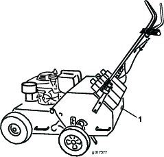
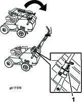
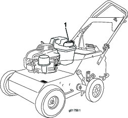
Whenever you need service, genuine Toro parts, or additional information, contact an Authorized Service Dealer or Toro Customer Service and have the model and serial numbers of your product ready. Figure 1 illustrates the location of the model and serial numbers on the product. Write the numbers in the space provided.
This manual identifies potential hazards and has safety messages identified by the safety alert symbol (Figure 2), which signals a hazard that may cause serious injury or death if you do not follow the recommended precautions.

This manual uses 2 words to highlight information. Important calls attention to special mechanical information and Note emphasizes general information worthy of special attention.
This spark ignition system complies with Canadian ICES-002.
Important: This engine is not equipped with a spark arrester muffler. It is a violation of California Public Resource Code Section 4442 to use or operate the engine on any forest-covered, brush-covered, or grass-covered land. Other states or federal areas may have similar laws.
Warning
CALIFORNIA
Proposition 65 Warning
The engine exhaust from this product contains chemicals known to the State of California to cause cancer, birth defects, or other reproductive harm.
Safety
Improper use or maintenance by the operator or owner can result in injury. To reduce the potential for injury, comply with these safety instructions and always pay attention to the safety alert symbol, which means Caution, Warning, or Danger—personal safety instruction. Failure to comply with the instruction may result in personal injury or death.
Safe Operating Practices
The following instructions are adapted from the ANSI B71.4—2004 and B71.8—2004 standard.
Training
-
Read the Operator’s Manual and other training material. If the operator(s) or mechanic(s) cannot read English it is the owner’s responsibility to explain this material to them.
-
Become familiar with the safe operation of the equipment, operator controls, and safety signs.
-
All operators and mechanics should be trained. The owner is responsible for training the users.
-
Never let children or untrained people operate or service the equipment. Local regulations may restrict the age of the operator.
-
The owner/user can prevent and is responsible for accidents or injuries occurring to himself or herself, other people or property.
Preparation
-
Evaluate the terrain to determine what accessories and attachments are needed to properly and safely perform the job. Only use accessories and attachments approved by the manufacturer.
-
Wear appropriate clothing including safety glasses and hearing protection. Long hair, loose clothing, or jewelry may get tangled in moving parts.
-
Inspect the area where the equipment is to be used and remove all objects such as rocks, toys, and wire which can be contacted by the aerator.
-
Use extra care when handling gasoline and other fuels. They are flammable and vapors are explosive.
-
Use only an approved container.
-
Never remove the gas cap or add fuel with the engine running.
-
Allow the engine to cool before refueling.
-
Do not smoke.
-
Never refuel or drain the aerator indoors.
-
-
Check that the controls, safety switches, and shields are attached and functioning properly. Do not operate unless they are functioning properly.
Operation
-
Never run an engine in an enclosed area.
-
Only operate in good light, keeping away from holes and hidden hazards.
-
Be sure all drives are in neutral before starting engine.
-
Never operate without the shields, covers, or other guards securely in place. Be sure all interlocks are functioning properly.
-
Do not change the engine governor setting or overspeed the engine.
-
Raise the tines, stop the machine, and stop the engine before leaving the operator’s position for any reason.
-
Stop the equipment and inspect the tines after striking an object or if an abnormal vibration occurs. Make necessary repairs before resuming operation.
-
Keep hands and feet away from the tine area.
-
Be alert, slow down, and use caution when making turns. Look behind and to the side before changing directions.
-
Slow down and use caution when crossing roads and sidewalks.
-
Do not operate the aerator under the influence of alcohol or drugs.
-
Lightning can cause severe injury or death. If lightning is seen or thunder is heard in the area, do not operate the machine; seek shelter.
-
Use extreme care when loading or unloading the aerator into a trailer or truck.
-
Use care when approaching blind corners, shrubs, trees, or other objects that may obscure vision.
-
Always be aware of obstacles that may be in the area of operation. Plan your aeration path to avoid contact with any obstacle by you or the machine.
Slope Operation
-
Do not make sudden turns or rapid speed changes.
-
Reduce speed and use extreme caution on slopes.
-
Remove or mark obstacles such as rocks, tree limbs, etc. from the operating area. Tall grass can hide obstacles.
Maintenance and Storage
-
Wait for all movement to stop before adjusting, cleaning, or repairing. Raise the tines, stop the machine, stop the engine, and disconnect the spark plug wire.
-
Clean grass and debris from the tines, drives, mufflers, and engine to help prevent fires. Clean up oil or fuel spillage.
-
Let the engine cool before storing and do not store near flame.
-
Shut off the fuel while storing or transporting on trailers. Do not store fuel near flames or drain indoors.
-
Park the aerator on level, hard ground. Never allow untrained personnel to service it.
-
Use jack stands or safety latches to support the machine when working under it.
-
Remove the spark plug wire before making any repairs.
-
Keep hands and feet away from moving parts. If possible, do not make adjustments with the engine running.
-
Keep all parts in good working condition and all hardware tightened. Replace all worn or damaged decals.
-
Use only Toro-approved attachments. The warranty may be voided if the machine is used with unapproved attachments.
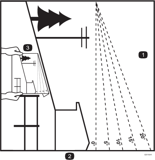
Slope Indicator
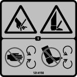
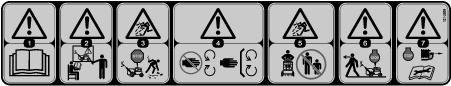
Safety and Instructional Decals
 |
Safety decals and instructions are easily visible to the operator and are located near any area of potential danger. Replace any decal that is damaged or lost. |


Setup
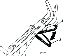
Unfolding the Handle
-
Raise the handle to the operating position.
-
Slide the oval locking rings down each side of the upper handle over the lower handle, locking the handle sections together.
Checking the Oil Level
Before operating, check the engine oil level to ensure that it has enough oil. Refer to Checking the Engine Oil Level, for oil specifications and instructions.
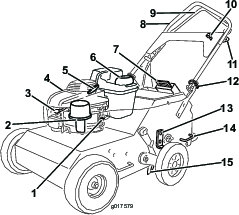
Product Overview
Recoil Starter
Pull the recoil starter handle to start engine (Figure 5).
Fuel Shut-off Valve
Close the fuel shut-off valve when transporting or storing the machine (Figure 5).
Throttle Lever
Before starting a cold engine, move the throttle lever forward to the Choke position. After the engine starts, pull the throttle lever back to the Fast position.
Note: A warm engine requires little or no choking.
Traction-Control Lever
The traction-control lever controls the forward, reverse, and neutral actions of the machine. Refer to Driving the Machine for more information.
Tine-Control Lever
The tine-control lever lifts the rear wheels, causing the rear of the machine to be supported on the aerating tines. Push the tine control lever down to lift the wheels and drop the tines. Pull it up to lower the wheels and raise the tines out of the ground.
| Length (handle in lowest position) | 147 cm (58 inches) |
| Length (handle in middle position) | 150 cm (59 inches) |
| Length (handle in highest position) | 155 cm (61 inches) |
| Length (with handle stored) | 107 cm (42 inches) |
| Width | 79 cm (31 inches) |
| Height (handle in lowest position) | 122 cm (48 inches) |
| Height (handle in middle position) | 127 cm (50 inches) |
| Height (handle in highest position) | 132 cm (52 inches) |
| Height (with handle stored) | 86 cm (34 inches) |
| Weight (as shipped with 1 weight) | 140.6 kg (310 lb) |
Attachments/Accessories
A selection of Toro approved attachments and accessories is available for use with the machine to enhance and expand its capabilities. Contact your Authorized Service Dealer or Distributor or go to www.Toro.com for a list of all approved attachments and accessories.
Operation
Note: Determine the left and right sides of the machine from the normal operating position.
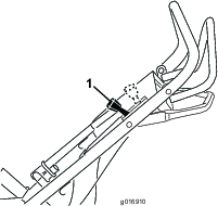
Adjusting the Handle
The height of the handle can be adjusted for comfortable operation. Stand behind the handle to determine the appropriate height settings.
-
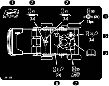
To adjust the handle height, position the hardware into one of three sets of holes on each side of the mainframe as shown in Figure 7, Figure 8, and Figure 9.
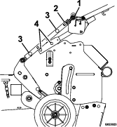
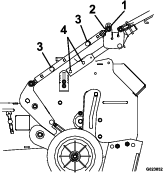
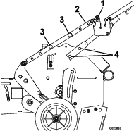
-
Secure the handle with both mounting bolts.
-
Adjust the tine ground engagement lever; refer to Adjusting the Tine Ground Engagement Lever.
Checking the Engine Oil Level
The engine crankcase can hold 0.55 liters (20 ounces) of oil. Use only high-quality SAE 10W-30 weight detergent oil that has the American Petroleum Institute (API) service classification SH, SJ, Sl or higher.
Note: When the crankcase is empty, pour about 3/4 of the crankcase capacity of oil in the crankcase, then follow the procedure in this section.
-
Move the machine to a level surface.
-
Clean around the dipstick (Figure 10).
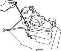
-
Remove the dipstick by rotating the cap counterclockwise and pulling it out.
-
Wipe the dipstick clean with a clean cloth.
-
Insert the dipstick into the filler neck, but do not rotate the cap clockwise to secure it, then remove it.
-
Read the oil level on the dipstick.
-
If the oil level reading is below the lower limit mark on the dipstick, remove the dipstick and slowly pour only enough oil into the filler hole to raise the oil level to the upper limit mark on the dipstick.
Important: Do not overfill the crankcase with oil and run the engine; engine damage will result. Drain the excess oil until the oil level reaches the upper limit mark on the dipstick.
-
Insert the dipstick into the filler neck and rotate the cap clockwise until it is tight.
Filling the Fuel Tank with Gasoline
Fuel tank capacity: 3.76 L (0.99 US gallon)
Danger
In certain conditions, gasoline is extremely flammable and highly explosive. A fire or explosion from gasoline can burn you and others and can damage property.
-
Fill the fuel tank outdoors, in an open area, and when the engine is cold. Wipe up any gasoline that spills.
-
Do not fill the fuel tank completely full. Add gasoline to the fuel tank until the level is 6 to 13 mm (1/4 to 1/2 in) below the bottom of the filler neck. This empty space in the tank allows the gasoline to expand.
-
Never smoke when handling gasoline, and stay away from an open flame or where a spark may ignite the gasoline fumes.
-
Store gasoline in an approved fuel container and keep it out of the reach of children.
-
Never buy more than a 30-day supply of gasoline.
Danger
When fueling, under certain circumstances, a static charge can develop, igniting the gasoline. A fire or explosion from gasoline can burn you and others and damage property.
-
Always place gasoline containers on the ground and away from your vehicle before filling.
-
Do not fill gasoline containers inside a vehicle or on a truck or trailer bed because interior carpets or plastic truck bed liners may insulate the container and slow the loss of any static charge.
-
When practical, remove gasoline-powered equipment from the truck or trailer and refuel the equipment with its wheels on the round.
-
If this is not possible, then refuel such equipment on a truck or trailer from a portable container, not from a gasoline dispenser nozzle.
-
If you must use a gasoline dispenser nozzle, keep the nozzle in contact with the rim of the fuel tank or container opening at all times until fueling is complete.
-
For best results, use only clean, fresh, unleaded gasoline with an octane rating of 87 or higher ((R+M)/2 rating method).
-
Oxygenated fuel with up to 10% ethanol or 15% MTBE by volume is acceptable.
-
Do not use ethanol blends of gasoline (such as E15 or E85) with more than 10% ethanol by volume. Performance problems and/or engine damage may result which may not be covered under warranty.
-
Do not use gasoline containing methanol.
-
Do not store fuel either in the fuel tank or fuel containers over the winter unless a fuel stabilizer is used.
-
Do not add oil to gasoline.
Important: Do not use fuel additives other than a fuel stabilizer/conditioner. Do not use fuel stabilizers with an alcohol base such as ethanol, methanol, or isopropanol.
-
Clean around the fuel tank cap (Figure 11).
-
Remove the cap from the tank.
-
Fill the fuel tank with unleaded gasoline to within 6 to 13 mm (1/4 to 1/2 inch) from the top of the tank. Do not fill into the filler neck.
Important: Do not fill the tank more than 6 mm (1/4 inch) from the top of the tank because the gasoline must have room to expand.
-
Install the fuel tank cap and wipe up any spilled gasoline.
Starting the Engine
-
Connect the wire to the spark plug.
-
Open the fuel valve by turn it in-line with the fuel hose ().
-
Move the throttle control all the way forward to the Choke position (Figure 12).
Note: Do not use the choke when the engine is warm.
-
Pull the starter handle lightly until you feel resistance, then pull it sharply. Allow the rope to return to the handle slowly.
-
When the engine starts, move the throttle control to the Fast position.
Note: The throttle setting governs the maximum drive speed of the aerator.
Stopping the Engine
-
Release the traction control lever and allow it to return to neutral.
-
Move the throttle lever all the way rearward to stop the engine.
Driving the Machine
-
To move forward, press the control lever forward (Figure 14). The further forward you push it, the faster the machine will travel.
-
To move in reverse, pull the control lever rearward (Figure 14). The further rearward you pull it, the faster the machine will travel.
Warning
The aerator tines are sharp and can puncture your feet or other body parts.
Use extreme care when moving in reverse so that you do not allow your feet to go close to the tines. Watch for and avoid obstacles you could trip over.
-
To turn the machine, move slowly and press down on the handles; turn the machine in the desired direction then resume normal operation.
-
To make zero turns, pull up on the tine ground engagement lever and raise the tines.
Important: Do not make a zero turn when the tines are down. Turning with the tines down will result in turf tearing.
-
To stop, release the control lever (Figure 14).
Note: If your machine is moving too slowly and not properly aerating, see Adjusting the Machine Ground Speed
Aerating
-
Drive the machine to the desired location and stop it.
-
Push the tine control lever down and forward to raise the rear wheels and engage the tines.
-
Drive the machine to aerate the desired area.
Note: The machine with aerate in both forward and reverse.
-
When finished, stop the machine and pull the tine control lever rearward and up to lower the rear wheels and lifts the tines out of the ground.
Important: Do not drive the machine across pavement or other hard surfaces without first raising the tines. Crossing hard surfaces with the tines lowered will damage the tines.
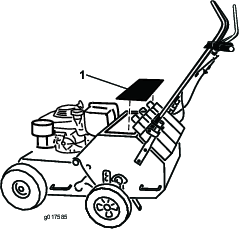
Adding Weight
To ensure that the tines penetrate fully into the soil, you can add weight to the back of the machine. The machine has three weight pockets that hold the weights (Figure 16). When placing weight, ensure that you have a balanced load; if using only one weight, place it in the center pocket and if using two, place them in the side pockets.
Adjusting the Coring Depth
A coring depth of 6.35 cm (2-1/2 inches) is recommended, but you can change the depth as follows:
-
Raise the tines, stop the machine, stop the engine, and disconnect the spark plug wire.
-
Loosen the nuts securing the wheel stop on the right side of the machine (Figure 17).
-
Raise the wheel stop to increase the coring depth and lower it to reduce the depth as required.
-
Tighten the nuts securely to lock the wheel stop in place.
-
Repeat steps 2 through 4 for the wheel stop on the left side of the machine. Set the wheel stops to the same height on each side.
Adjusting the Tine Ground Engagement Lever
-
Raise the tines, stop the machine, stop the engine, and disconnect the spark plug wire.
-
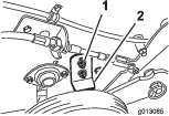
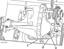
The wheel arm and the pivot shaft assembly should have surface-to-surface contact (Figure 18). If not, check the distance of the lower lift linkage and adjust if necessary.
-
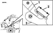
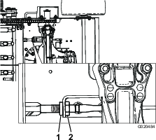
The lower ball joint bolt on the upper link rod should be in line with the handle pivot bolt (Figure 19). If not, loosen the lock nuts on the lift link strap ball joints, adjust as necessary, and tighten the locknuts. Care should be taken to adjust the upper and lower ball joints evenly.
-
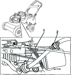
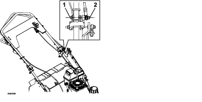
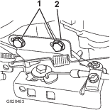
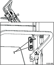
Check the distance between the tine ground engagement lever and the self-propel drive bail as shown in Figure 20 .
Note: The distance should be approximately 38-44 mm (1 1/2–1 3/4 inches); if it is not, then proceed to step 5.
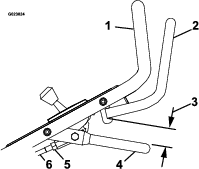
-
Loosen both jam nuts on both ends of the link rod next to the ball joints.
-
Turn the link rod until the proper distance is reached.
-
Tighten both jam nuts on the link rod next to the ball joints.
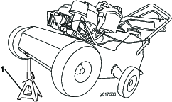
Securing the Machine for Transport
When transporting the machine on a trailer, always use the following procedure:
Important: Do not operate or drive the machine on roadways.
-
Drive the machine onto that trailer, stop the machine, stop the engine, turn off the fuel valve, and disconnect the spark plug wire.
Important: If you do not turn off the fuel valve, the engine may flood during transport.
-
Secure the machine to the trailer with chains or straps using the tie-down/lift loops (Figure 5).
Operating Tips
-
For best performance and maximum tine penetration, water the turf thoroughly the day before aerating.
-
Clean the area of debris before using the machine.
-
Mark and avoid shallow obstacles such as sprinkler heads and invisible fence wires.
Maintenance
Recommended Maintenance Schedule(s)
| Maintenance Service Interval | Maintenance Procedure |
|---|---|
| After the first 8 hours |
|
| After the first 10 hours |
|
| After the first 25 hours |
|
| Before each use or daily |
|
| Every 25 hours |
|
| Every 50 hours |
|
| Every 100 hours |
|
| Every 200 hours |
|
| Every 250 hours |
|
| Every 300 hours |
|
| Yearly or before storage |
|
Caution
If you leave the spark pug wire connected, someone could accidently start the engine and seriously injure you or other bystanders.
Before performing any maintenance, park the unit on a level surface, stop the engine, and disconnect the spark plug wire. Set the wire aside so that it does not accidentally contact the spark plug.
Pre-Maintenance Procedures
Accessing the Tines
The machine has a rear access panel that you can remove to access and maintain the tines (Figure 21).
Warning
If you operate the machine with the rear access panel removed, some one could be severely injured by contact with the moving tines or by flying debris.
Always securely install the rear access panel before operating the machine.
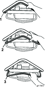
Tipping the Machine
If you need to work on the underside of the machine, you can tip it back until it is resting on the rear guard (Figure 22). Do not tip the machine forward or you will foul the air cleaner with gasoline. Secure the machine with a jack stand before working under it.
Warning
Mechanical or hydraulic jacks may fail to support machine and cause a serious injury.
-
Use jack stands when supporting machine.
-
Do not use hydraulic jacks.
Lubrication
Greasing the Center Tines
| Maintenance Service Interval | Maintenance Procedure |
|---|---|
| Before each use or daily |
|
-
Raise the tines, stop the machine, stop the engine, and disconnect the spark plug wire.
-
Remove the rear access panel; refer to Accessing the Tines
-
Manually rotate the 2 center tine assemblies until you can see the grease fittings (Figure 23).
-
Wipe the grease fittings with a clean rag.
-
Install a grease gun onto the fitting and gently apply 2 or 3 pumps of #2 multi-purpose lithium base grease.
Important: Excessive grease pressure may damage the seals.
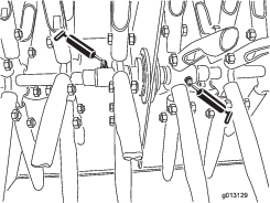
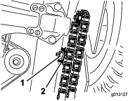
Lubricating the Drive Chains
| Maintenance Service Interval | Maintenance Procedure |
|---|---|
| Every 25 hours |
|
-
Raise the tines, stop the machine, stop the engine, and disconnect the spark plug wire.
-
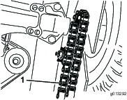
Raise the front of the machine to gain access to the chains (Figure 24) and block it in place.
Caution
If you do not securely block the up the front of the machine, the machine could fall on you during service, injuring you.
Ensure that you place a jack-stand or block under the front of the machine to hold it up securely.
Important: Do not raise the rear of the machine. Raising the rear of the machine will cause the engine to flood and the air cleaner to be fouled with gasoline.
-
Apply a general purpose oil (10W30) onto the lower chain span while rotating the front wheel to expose un-oiled chain links until the whole chain is oiled.
-
Repeat step 3 for the other chain.
-
Wipe up any oil that spilled and lower the machine to the ground when finished.
Engine Maintenance
Servicing the Air Cleaner
| Maintenance Service Interval | Maintenance Procedure |
|---|---|
| Every 25 hours |
|
| Every 300 hours |
|
Important: Do not operate the engine without the air filter assembly; extreme engine damage may occur.
-
Stop the engine and wait for all moving parts to stop.
-
Disconnect the wire from the spark plug.
-
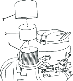
Remove the cover and clean it thoroughly ().
Note: Be careful to prevent dirt and debris from falling into the base.
-
Remove the foam pre-cleaner and wash it with a mild detergent and water, then blot it dry (Figure 25).
-
Remove and inspect the paper air filter (); discard it if it is excessively dirty.
Important: Do not try to clean a paper filter.
-
Wipe dirt from the base and the cover with a moist rag.
Note: Be careful to prevent dirt and debris from entering the air duct leading to the carburetor.
-
Install the foam pre-cleaner onto the paper air filter.
Note: Use a new paper air filter if you discarded the old one.
-
Install the air filter assembly and cover.
Changing the Engine Oil
| Maintenance Service Interval | Maintenance Procedure |
|---|---|
| After the first 8 hours |
|
| Every 50 hours |
|
| Oil Capacity | |
| With oil filter | 0.85 L (29 ounces) |
| Without oil filter | 0.65 L (22 ounces) |
-
Run the engine to warm the engine oil.
Note: Warm oil flows better and carries more contaminants.
Warning
Oil may be hot after engine has been run, and contact with hot oil can cause severe personal injury.
Avoid contacting the hot engine oil when you drain it.
-
Stop the engine and wait for all moving parts to stop.
-
Disconnect the wire from the spark plug.
-
Place a drain pan on the ground to the right of the machine.
-
Remove the dipstick (Figure 26).
-
Remove the drain plug (Figure 27) and tip the machine so the oil flows to the pan.
-
Tip the machine upright again, clean the oil from the frame with a rap and replace the drain plug.
-
Insert the dipstick into the filler neck and rotate the cap clockwise until it is tight.
-
Slowly pour oil into the oil fill tube, periodically checking the level with the dipstick, until the dipstick indicates that the engine is full. Do not overfill. (Max. fill: 0.55 L (20 oz), type: SAE 30W detergent oil with an API service classification of SH, SJ, SL, or higher.)
Note: If you overfill the engine, pour some oil out of it.
-
Install the dipstick securely.
-
Recycle the used oil according to local codes.
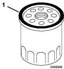
Changing the Oil Filter
| Maintenance Service Interval | Maintenance Procedure |
|---|---|
| Every 100 hours |
|
-
Drain the engine oil; refer to Changing the Engine Oil.
-
Place a rag under the oil filter (Figure 27) to catch any oil that may leak out as you remove the filter.
-
Remove the oil filter.
-
Use your finger to coat the gasket on the new filter with oil (Figure 28).
-
Install the new filter and hand tighten it 2/3 turn only.
-
Insert the dipstick into the filler neck and rotate the cap clockwise until it is tight.
-
Slowly pour oil into the oil fill tube, periodically checking the level with the dipstick, until the dipstick indicates that the engine is full. Do not overfill. (Max. fill: 0.55 L (20 oz), type: SAE 30W detergent oil with an API service classification of SH, SJ, SL, or higher.)
Note: If you overfill the engine, pour some oil out of it.
-
Install the dipstick securely.
-
Connect the wire to the spark plug.
-
Run the engine for about 3 minutes.
-
Stop the engine, wait for all moving parts to stop, and check for oil leakage around the filter.
-
Check and add oil to compensate for the oil in the oil filter. Do not overfill.
-
Recycle the used oil filter according to local codes.
Servicing the Spark Plug
| Maintenance Service Interval | Maintenance Procedure |
|---|---|
| Every 100 hours |
|
| Every 200 hours |
|
Use an NGK BPR6ES spark plug or equivalent.
-
Stop the engine and wait for all moving parts to stop.
-
Disconnect the wire from the spark plug.
-
Clean around the spark plug.
-
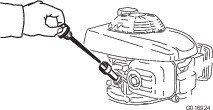
Remove the spark plug from the cylinder head.
Important: Replace a cracked, fouled, or dirty spark plug. Do not clean the electrodes because grit entering the cylinder can damage the engine.
-
Set the gap on the plug to 0.76 mm (0.030 inch) ().

-
Carefully install the spark plug by hand (to avoid cross threading) until it is hand tight.
-
Tighten the spark plug an additional 1/2 turn if it is new; otherwise, tighten it an additional 1/8 to 1/4 turn.
Important: A loose spark plug can become very hot and can damage the engine; overtightening a spark plug may damage the threads in the cylinder head.
-
Connect the wire to the spark plug.
Fuel System Maintenance
Replacing the Fuel Filter
| Maintenance Service Interval | Maintenance Procedure |
|---|---|
| Every 250 hours |
|
-
Stop the engine and wait for it to cool down.
Important: Drain gasoline from a cold engine only.
-
Disconnect the wire from the spark plug.
-
Close the fuel valve.
-
Clamp off the fuel line on either side of the fuel filter (Figure 30) to prevent fuel from leaking out when you remove the filter.
-
Squeeze the ends of the hose clamps together and slide them away from the filter (Figure 30).
-
Remove the filter from the fuel lines.
-
Install a new filter and move the hose clamps close to the filter (Figure 30).
-
Remove the clamps from the fuel lines.
-
Open the fuel shutoff valve.
Drive System Maintenance
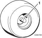
Checking the Tire Pressure
| Maintenance Service Interval | Maintenance Procedure |
|---|---|
| Before each use or daily |
|
Maintain the air pressure in the tires as specified. Check the tires when they are cold to get the most accurate reading.
Pressure: 317 kPa (46 psi)
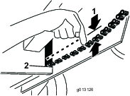
Checking the Tension of Aerator Drive Chains
| Maintenance Service Interval | Maintenance Procedure |
|---|---|
| After the first 10 hours |
|
| Every 50 hours |
|
-
Raise the tines, stop the machine, stop the engine, and disconnect the spark plug wire.
-
Raise the front of the machine to gain access to the chains and block it in place.
Caution
If you do not securely block the up the front of the machine, the machine could fall on you during service, injuring you.
Ensure that you place a jackstand or block under the front of the machine to hold it up securely.
Important: Do not raise the rear of the machine. Raising the rear of the machine will casue the engine to flood and the air cleaner to be fouled with gasoline.
-
Pull down on each chain near the opening in the frame with 9 kg (20 pounds) of force (Figure 32). If a chain flexes more than 3 mm (1/8 inch), tighten it as follows:
-
Loosen the nut securing the idler sprocket of the chain you are tensioning (Figure 33).
-
Pull down on the idler sprocket until the slack is taken out of the chain and there is more than 6 mm (1/4 inch) of space between the chain and the bottom of the opening in the frame when you apply 9 kg (20 pounds) of force to the chain.
-
Tighten the idler sprocket nut and torque it to 40.6 N-m (30 ft-lb).
-
Belt Maintenance
Checking the Hydrostatic Drive Belt
| Maintenance Service Interval | Maintenance Procedure |
|---|---|
| After the first 25 hours |
|
| Every 50 hours |
|
-
Raise the tines, stop the machine, stop the engine, and disconnect the spark plug wire.
-
Raise the front of the machine to gain access to the pump drive belt and block it in place.
Caution
If you do not securely block the up the front of the machine, the machine could fall on you during service, injuring you.
Ensure that you place a jack stand or block under the front of the machine to hold it up securely.
Important: Do not raise the rear of the machine. Raising the rear of the machine will cause the engine to flood and the air cleaner to be fouled with gasoline.
-
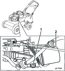
Push on a span of the drive belt with 9 kg (20 pounds) of force (Figure 34). If the belt flexes more than 3 mm (1/8 inch), tighten it as follows:
-
Loosen the nut securing the idler pulley (Figure 34).
-
Push the idler pulley to the left to tighten the belt .
-
Tighten the idler pulley nut and torque it to 40.6 N-m (30 ft-lb).
-
Controls System Maintenance
Adjusting the Machine Ground Speed
-
Loosen the 2 bolts securing the cable attachment bracket and slide it as far as possible to the left then tighten the 2 bolts (Figure 35).
-
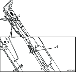
Adjust the traction drive cable at the lower anchor by moving the nut to the end of the thread and tightening the jam nut (Figure 36).
-
Adjust the traction drive cable at the handle as follows:
-
Adjust the reverse speed stop as follows:
Hydraulic System Maintenance
Changing the Hydraulic Transmission Fluid
| Maintenance Service Interval | Maintenance Procedure |
|---|---|
| Every 100 hours |
|
-
Raise the tines, stop the machine, stop the engine, and disconnect the spark plug wire.
-
Drain the fuel from the fuel tank.
-
Slide the oval locking rings on the handle upward, and fold the handle towards the engine.
-
Slowly lift the front of the machine until the back of the machine and weight pockets are resting on the ground. Stabilize the machine with an overhead hoist.
Note: Using two people or an overhead hoist to lift the machine will make this easier.
-
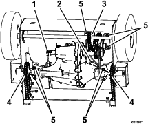
Remove the transmission from the machine (Figure 39).
Note: It will take two people or a second hoist to safely remove the transmission.
-
Disconnect the self-propel drive bail cable from the transmission.
-
Remove the drive belt from the transmission pulley by loosening the nut on the idler pulley.
-
Remove and retain the connecting link from the front axle chain sprocket, and remove the chain.
-
Loosen the drive chain idler sprockets on each side of the unit. Remove and retain the connecting link from the drive chains, and remove the drive chain from the transmission sprockets.
-
Support the transmission, remove and retain its mounting hardware, and carefully lower the transmission to the ground.
-
-
Carefully clean the area around the expansion tank and oil-fill port. It is important that no dirt or contamination enter the hydraulic system.
-
Remove and retain the oil-fill port fitting and position the transmission so the oil will drain completely out of the housing.
-
When all the oil has drained from the transmission, remove and retain the #10-32 x 1/2 inch self-tapping screw and ratchet fastener holding the expansion tank to the housing.
-
Remove the expansion tank and drain the oil.
Note: Do not remove the vent cap from the tank.
Note: Do not remove the tank hose or O-ring unless a replacement is needed.
-
Inspect the belt, pulleys, sprockets, and bearings; replace as required.
-
Install the previously removed expansion tank by first inserting the hose into the tank. Place the tank opening over the O-ring and push down to ensure a proper seal. Install the #10–32 x 1/2 inch self tapping screw and torque it to 2.8 N-m (25 in-lb).
-
Fill the transmission at the oil-fill port until the oil level is 13–32 mm (1/2–1 1/4 inches) below the top of the fill port.
Toro Premium Hydro Oil is recommended. Mobil 1 15W50 is an acceptable alternative.
-
Install the previously removed oil-fill port fitting.
-
Install the previously removed transmission.
-
With the transmission belt on the engine pulley and the idler pulley, loosely install the transmission using the previously removed mounting hardware.
-
Install the transmission belt on the transmission pulley.
-
Install the drive chains onto the idler and transmission sprockets.
-
Install the chain on the front axle sprocket. Ensure that the front axle sprocket is aligned with the sprocket on the transmission.
-
Tighten the 7 transmission mounting bolts.
-
Tension the transmission belt; refer to Checking the Hydrostatic Drive Belt.
-
Tension the tine drive chains; refer to Checking the Tension of Aerator Drive Chains.
-
Connect the self-propel drive bail cable.
-
-
Carefully remove the jackstands, lower the machine to the ground, and remove the overhead hoist hooks.
-
Raise and lock the handle into the operating position.
-
Check the gap between the handle and the bail. If the handle contacts the bail or if there is more than a 3mm (1/8 inch) gap, refer to Adjusting the Machine Ground Speed.
Tine Maintenance
Checking/Replacing Tines
| Maintenance Service Interval | Maintenance Procedure |
|---|---|
| Before each use or daily |
|
-
Raise the tines, stop the machine, stop the engine, and disconnect the spark plug wire.
-
Remove the rear access panel; refer to Accessing the Tines
-
Manually rotate the tines on the shaft, inspecting them for wear or damage.
-
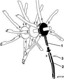
If any are damaged or broken, remove the nut and bolt securing the tine to the tine assembly (Figure 40).
-
Remove the tine and replace it with a new one. Ensure that the new tine is facing the same direction as the other tines on the assembly.
-
Secure the new tine with the bolt and nut you removed previously and torque them to 40.6 N-m (30 ft-lb).
-
When all tines have been inspected and replaced as needed, lower the machine to the ground and engage the hydrostatic drive.
Storage
-
Raise the tines, stop the machine, stop the engine, and disconnect the spark plug wire.
-
Remove dirt and grime from the entire machine.
Important: You can wash the machine with mild detergent and water. Do not pressure wash the machine. Avoid excessive use of water, especially near the engine and hydrostatic drive.
-
Service the air cleaner; refer to Servicing the Air Cleaner.
-
Grease the chains and floating tine assemblies; refer to Lubrication.
-
Change the engine oil; refer to Changing the Engine Oil.
-
Check and tighten all bolts, nuts, and screws. Repair or replace any part that is damaged.
-
Paint all scratched or bare metal surfaces. Paint is available from your Authorized Service Dealer.
-
Store the machine in a clean, dry garage or storage area.
-
Cover the machine to protect it and keep it clean.
Troubleshooting
| Problem | Possible Cause | Corrective Action |
|---|---|---|
| Engine will not start. |
|
|
| The machine vibrates abnormally. |
|
|
| The machine will not pull itself up hills. |
|
|
| The front wheels move but the tines do not. |
|
|
| The engine smokes when starting. |
|
|
| The engine is hard to start after transporting it. |
|
|
| The ground speed is slow. |
|
|