
| Maintenance Service Interval | Maintenance Procedure |
|---|---|
| Before each use or daily |
|
Introduction
This machine is a ride-on, reel-blade lawn mower intended to be used by professional, hired operators in commercial applications. It is primarily designed for cutting grass on well-maintained turf. Using this product for purposes other than its intended use could prove dangerous to you and bystanders.
Read this information carefully to learn how to operate and maintain your product properly and to avoid injury and product damage. You are responsible for operating the product properly and safely.
Visit www.Toro.com for more information, including safety tips, training materials, accessory information, help finding a dealer, or to register your product.
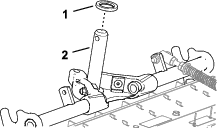
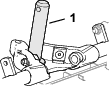
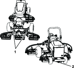
Whenever you need service, genuine Toro parts, or additional information, contact an Authorized Service Dealer or Toro Customer Service and have the model and serial numbers of your product ready. Figure 1 identifies the location of the model and serial numbers on the right front frame member of the product. Write the numbers in the space provided.
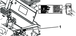
Important: With your mobile device, you can scan the QR code on the serial number plate (if equipped) to access warranty, parts, and other product information.
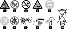
This manual identifies potential hazards and has safety messages identified by the safety-alert symbol (Figure 2), which signals a hazard that may cause serious injury or death if you do not follow the recommended precautions.

This manual uses 2 words to highlight information. Important calls attention to special mechanical information and Note emphasizes general information worthy of special attention.
This product complies with all relevant European directives. For details, please see the separate product specific Declaration of Conformity (DOC) sheet.
It is a violation of California Public Resource Code Section 4442 or 4443 to use or operate the engine on any forest-covered, brush-covered, or grass-covered land unless the engine is equipped with a spark arrester, as defined in Section 4442, maintained in effective working order or the engine is constructed, equipped, and maintained for the prevention of fire.
The enclosed engine owner’s manual is supplied for information regarding the US Environmental Protection Agency (EPA) and the California Emission Control Regulation of emission systems, maintenance, and warranty. Replacements may be ordered through the engine manufacturer.
Warning
CALIFORNIA
Proposition 65 Warning
Diesel engine exhaust and some of its constituents are known to the State of California to cause cancer, birth defects, and other reproductive harm.
Battery posts, terminals, and related accessories contain lead and lead compounds, chemicals known to the State of California to cause cancer and reproductive harm. Wash hands after handling.
Use of this product may cause exposure to chemicals known to the State of California to cause cancer, birth defects, or other reproductive harm.
Safety
This machine has been designed in accordance with EN ISO 5395 (when you complete the setup procedures) and ANSI B71.4-2017.
General Safety
This product is capable of amputating hands and feet and of throwing objects.
-
Read and understand the contents of this Operator’s Manual before starting the engine.
-
Use your full attention while operating the machine. Do not engage in any activity that causes distractions; otherwise, injury or property damage may occur.
-
Do not put your hands or feet near moving components of the machine.
-
Do not operate the machine without all guards and other safety protective devices in place and functioning properly on the machine.
-
Keep bystanders and children out of the operating area. Never allow children to operate the machine.
-
Shut off the engine, remove the key, and wait for all movement to stop before you leave the operator’s position. Allow the machine to cool before adjusting, servicing, cleaning, or storing it.
Improperly using or maintaining this machine can result in injury.
To reduce the potential for injury, comply with these safety instructions
and always pay attention to the safety-alert symbol  , which means
Caution, Warning, or Danger—personal safety instruction. Failure
to comply with these instructions may result in personal injury or
death.
, which means
Caution, Warning, or Danger—personal safety instruction. Failure
to comply with these instructions may result in personal injury or
death.
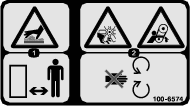
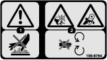
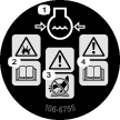
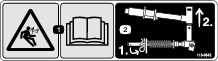
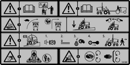
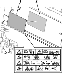
Safety and Instructional Decals
|
Safety decals and instructions are easily visible to the operator and are located near any area of potential danger. Replace any decal that is damaged or missing. |


CE Compliant Machines
Setup
Note: Determine the left and right sides of the machine from the normal operating position.
Preparing the Machine
-
Park the machine on a level surface, lower the cutting units, and engage the parking brake.
-
Shut off the engine, remove the key, and wait for all moving parts to stop.
-
Check the tire air pressure before use; refer toChecking the Tire Air Pressure.
Note: The tires are overinflated for shipping. Adjust the tire air pressure before operating the machine.
-
Check the rear-axle lubricant level; refer to Checking the Oil Level of the Rear Axle.
-
Check the hydraulic-fluid level; refer to Checking the Hydraulic-Fluid Level.
-
Grease the machine; refer to Greasing the Bearings and Bushings.
Important: Failure to properly grease the machine will result in premature failure of critical parts.
-
Open the hood and check the coolant level; refer to Checking the Coolant Level.
-
Check the level of the engine-oil level, and close and latch the hood; refer to Checking the Engine-Oil Level.
Note: The engine ships with oil in the crankcase; however, check the oil level before and after the engine is first started.
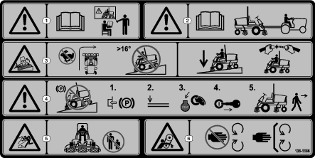
Adjusting the Front Cutting Unit Roller Position
Note:
-
Determine if you need to adjust the roller position. The width of the cutting unit that you install determines the roller position at the roller support as follows:
-
27-inch cutting units—upper mounting holes of the roller support.
-
32-inch cutting units—lower mounting holes of the roller support.
-
-
If needed, remove the capscrew, locknut, and roller.
-
Align the roller to the other roller support holes.
-
Secure the roller to the roller support with the capscrew and locknut.
-
Repeat steps 2 through 4 at the other side of the machine.
Installing the Cutting Units
Parts needed for this procedure:
| Front hose guide (right) | 1 |
| Front hose guide (left) | 1 |
Preparing the Machine
-
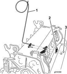
Remove the reel motors from the shipping brackets.
-
Remove and discard the shipping brackets.
Preparing the Cutting Units
-
Remove the cutting units from the cartons.
-
Assemble and adjust as described in the cutting unit Operator's Manual.
-
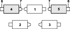
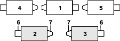
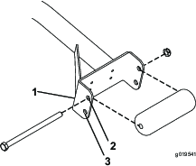
Make sure that the counterweight (Figure 4) is installed at the proper end of the cutting unit as described in the cutting unit Operator's Manual.
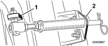
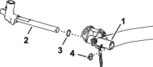
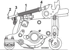
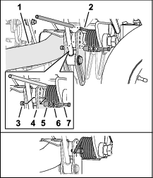
Positioning the Turf Compensating Spring
All the cutting units are shipped with the turf compensation spring mounted at the right side of the cutting unit. Ensure that the turf compensation spring is mounted to the same side of the cutting unit as the reel drive motor.
Note: When installing or removing the cutting units, make sure that the hairpin is installed in the spring-rod hole next to the rod bracket. Otherwise, the hairpin cotter must be installed in the hole in the end of the rod.
-
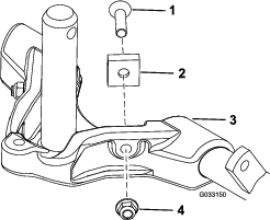
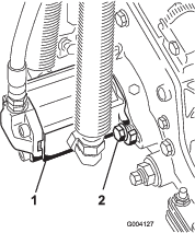
Remove the 2 carriage bolts and nuts securing the rod bracket to the cutting-unit tabs (Figure 5).
-
Remove the flange nut securing the spring-tube bolt to the carrier-frame tab (Figure 5), and remove the assembly.
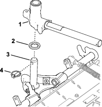
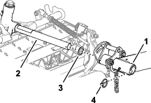
-
Mount the spring-tube bolt to the opposite tab on the carrier frame and secure with the flange nut.
Note: Position the bolt head to the outer side of the tab as shown in Figure 6.
-
Mount the rod bracket to the cutting unit tabs with the carriage bolts and nuts (Figure 6). On the cutting unit, mount the left hose guide to the front of the cutting unit tabs when installing the rod bracket (Figure 9).
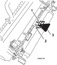
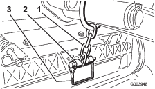
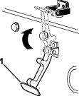
Installing the Kickstand
For each cutting unit, secure the kickstand to the chain bracket with the snapper pin (Figure 7).
Installing the Hose Guide
Increasing the Rear Cutting Unit Pivot Angle
Preparing to Install the Cutting Units
Installing the Front Cutting Units
-
Slide a cutting unit under the lift arm (Figure 15).
-
Insert the shaft of the carrier frame into the pivot yoke of the lift arm.
-
Secure the carrier-frame shaft to the pivot yoke with the lynch pin.
-
Repeat steps 1 and 3 at the other front cutting-unit positions.
Installing the Rear Cutting Units to the Lift Arms
Cutting Units adjusted for a 1.2 cm (3/4 inch) or Higher
Height of Cut
-
Slide a cutting unit under the lift arm (Figure 16).
-
Insert the lift-arm shaft into the lift arm and secure it with the lynch pin.
-
Repeat step 2 for the other rear cutting unit.
Installing the Rear Cutting Units to the Lift Arms
Cutting Units adjusted for a 1.2 cm (3/4 inch) or Lower
Height of Cut
-
Remove the lynch pin and washer securing the lift-arm pivot shaft to the lift arm and slide the lift-arm pivot shaft out of the lift arm (Figure 17).
-
Insert the lift-arm yoke onto the carrier frame shaft (Figure 18).
-
Slide a cutting unit under the lift arm (Figure 19).
-
Insert the lift-arm shaft into the lift arm and secure it with the lynch pin.
-
Repeat steps 1 through 4 for the other rear cutting unit.
Installing the Cutting Unit Lift-Arm Chains
Secure the lift-arm chain to the chain bracket with the snapper pin (Figure 20).
Note: Use the number of chain links described in the cutting unit Operator's Manual.
Installing the Reel Motors
-
Coat the spline shaft of the reel motor with clean grease.
-
Oil the reel motor O-ring and install it onto the motor flange.
-
Install the motor by rotating it clockwise so that the motor flanges clear the bolts (Figure 21).
-
Rotate the motor counterclockwise until the flanges encircle the bolts, and then tighten the bolts.
Important: Make sure that the reel motor hoses are not twisted, kinked, or at risk of being pinched.
-
Torque the mounting bolts to (27 to 33 ft-lb).
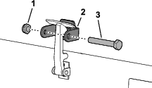
Installing the Hood Lock for CE Compliance
Parts needed for this procedure:
| Hood-lock bracket | 1 |
| Rivet | 2 |
| Screw (1/4 x 2 inch) | 1 |
| Flat washer (1/4 inch) | 2 |
| Locknut (1/4 inch) | 1 |
-
Unhook the hood latch from the hood-latch bracket (Figure 22).
-
Remove the 2 rivets securing the hood-latch bracket to the hood (Figure 23).
-
Remove the hood-latch bracket from the hood.
-
While aligning the mounting holes, position the CE lock bracket and the hood-latch bracket onto the hood.
Note: The lock bracket must be against the hood (Figure 23).Do not remove bolt and nut assembly from the lock-bracket arm.
-
Align the washers with the holes on the inside of the hood.
-
Rivet the brackets and the washers to the hood (Figure 24).
-
Hook the latch onto the hood-latch bracket (Figure 25).
-
Screw the bolt into the other arm of hood-lock bracket to lock the latch in position (Figure 26).
-
Tighten the bolt securely but do not tighten the nut.
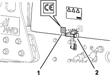
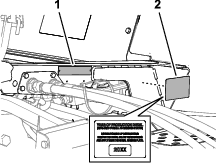
Applying the CE Decals
Parts needed for this procedure:
| CE decal | 1 |
| Production year decal | 1 |
| Warning decal | 1 |
|
CE decal—on the hood near the hood lock. |
 |
|
Production year decal—on frame of the machine near the serial plate. |
 |
|
CE warning decal—over the standard warning decal. |
 |
-
Clean the surface of the machine with alcohol and a clean rag where you are adhering the decal; refer to the CE Decal Location Table.
-
Wait the surface to dry.
-
Remove the backing from the decal.
-
Adhere the decal to the surface.
-
Repeat steps 1 through 4 for the other decals.
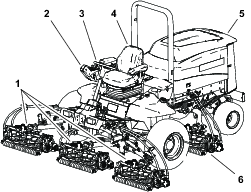
Product Overview
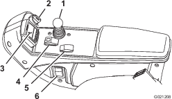
Brake Pedals
The 2 foot pedals (Figure 31) operate individual wheel brakes for turning assistance and to aid in obtaining better side hill traction.
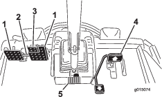
Pedal-Locking Latch
The pedal-locking latch (Figure 31) connects the pedals together to engage the parking brake.
Parking-Brake Pedal
To engage the parking brake, (Figure 31) connect the pedals together with the pedal-locking latch, push down on the right brake pedal while engaging the toe pedal. To release the parking brake, press 1 of the brake pedals until the parking-brake latch retracts.
Traction Pedal
The traction pedal (Figure 31) controls the forward and reverse operation. Press the top of the pedal to move forward and the bottom of the pedal to move backward. Ground speed depends on how far you press the pedal. For no load, maximum ground speed, press the engine-speed switch to high idle and then fully press the traction pedal.
To stop, reduce your foot pressure on the traction pedal and allow it to return to the center position.
Tilt Steering Pedal
To tilt the steering wheel toward you, press the foot pedal (Figure 31) down, and pull the steering tower toward you to the most comfortable position and then release the pedal.
Speed-Limiter Screws
Adjust the screw(s) (Figure 32) to limit the amount the traction pedal can be pressed in the forward or reverse direction to limit speed.
Important: The speed-limiter screw must stop the traction pedal before the pump reaches full stroke ; otherwise, damage to the pump may occur.
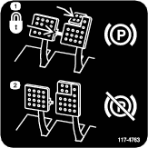
Mow-Speed Limiter
When the mow-speed limiter (Figure 32) is rotated forward, it allows the cutting units to engage and limits the maximum ground speed during mowing. You change the position of the spacers to adjust mowing ground speed. When driving machine between job sites, rotate the mow-speed limiter back for maximum transport speed.
Lower Mow/Raise Control Lever
Use the lower mow/raise control lever (Figure 33) raises and lowers the cutting units. The lever also starts and stops the reels when the reels are enabled in the mow mode.
Note: The cutting units cannot be lowered when the mow/transport lever is in the transport position.
Key Switch
The key switch (Figure 33) has 3 positions: OFF, ON/PREHEAT, and START.
InfoCenter
The InfoCenter LCD display shows information about your machine, such as the operating status, various diagnostics, and other information about the machine (Figure 33).
PTO Switch
The PTO switch (Figure 33) has 2 positions: ENGAGE and DISENGAGE. Press the PTO button forward to engage the cutting-unit blades. Press the button back to disengage the cutting-unit blades.
Engine-Speed Switch
The engine-speed switch (Figure 33) has 2 modes to change the engine speed. By momentarily tapping the switch, you can increase or decrease the engine speed in 100 rpm increments. Press and hold the switch to move the engine speed directly to high or low idle, depending on which end of the switch you press.
Headlight Switch
Press the switch to turn on the headlights (Figure 33).
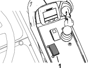
Power Point
Use the power point (Figure 34) to power optional 12-volt electrical accessories.
Bag Holder
Use the bag holder (Figure 34) for storage.
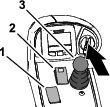
Backlap Levers
Use the backlap levers to control the cutting unit rotation direction when backlapping the reels (Figure 35).
Using the InfoCenter LCD Display
The InfoCenter LCD display shows information about your machine, such as the operating status, various diagnostics, and other information about the machine (Figure 36) There is a splash screen and main information screen of the InfoCenter. You can switch between the splash screen and main information screen, at any time, by pressing any of the InfoCenter buttons and then selecting the appropriate directional arrow.
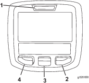
-
Left Button, Menu Access/Back Button—press this button to access the InfoCenter menus. You can use it to back out of any menu you are currently using.
-
Middle Button—use this button to scroll down menus.
-
Right Button—use this button to open a menu where a right arrow indicates additional content.
-
Manual Fan Reversal—activated by pressing the left and right buttons simultaneously.
-
Beeper—activated when lowering the decks or for advisories and faults.
Note: The purpose of each button may change depending on what is required at the time. Each button is labeled with an icon displaying its current function.
| SERVICE DUE | Indicates when scheduled service should be performed |
 | Hours remaining until service |
 | Reset the service hours  |
 | Engine rpm/status—indicates the engine speed |
 | Info icon |
 | Hour meter |
 | Fast |
 | Slow |
 | Fan reversal—indicates when the fan is reversed |
 | Stationary regeneration required |
 | Air intake heater is active |
 | Raise cutting units |
 | Lower cutting units |
 | Operator must sit in seat |
 | Parking brake indicator—indicates when the parking brake is On |
 | Identifies the range as High |
 | Neutral |
 | Identifies the range as Low |
 | Coolant temperature—indicates the engine coolant temperature in either °C or °F |
 | Temperature (hot) |
 | Denied or not allowed |
 | PTO is engaged |
 | Engine Start |
 | Stop or shutdown |
 | Engine |
 | Key switch |
 | Indicates when the cutting units are being lowered |
 | Indicates when the cutting units are being raised |
 | PIN code |
 | Hydraulic fluid temperature—indicates the temperature of the hydraulic fluid |
 | CAN bus |
 | InfoCenter |
 | Bad or failed |
 | Bulb |
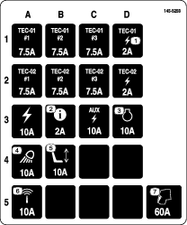
 | Output of TEC controller or control wire in harness |
 | High: over allowed range |
 | Low: under allowed range |
 | Out of range |
 | Switch |
 | Operator must release switch |
 | Operator should change to indicated state |
| Symbols are often combined to form sentences. Some examples are shown below | |
 | Operator should put machine in neutral |
 | Engine start denied |
 | Engine shutdown |
 | Engine coolant too hot |
 | Hydraulic fluid too hot |
 | NOx control diagnosis malfunction; drive the machine back to the shop and contact your authorized Toro distributor (software version F and later). |
 | DPF ash accumulation notification. Refer to DPF Ash Accumulation in the maintenance section for details. |
 | Sit down or set parking brake |
Accessible
only by entering PIN
Using the Menus
To access the InfoCenter menu system, press the menu access button while at the main screen. This will bring you to the main menu. Refer to the following tables for a synopsis of the options available from the menus:
| Main Menu | |
| Menu Item | Description |
| Faults | The Faults menu contains a list of the recent machine faults. Refer to the Service Manual or your authorized Toro distributor for more information on the Faults menu and the information contained there. |
| Service | The Service menu contains information on the machine such as hours of use counters and other similar numbers. |
| Diagnostics | The Diagnostics menu displays the state of each machine switch, sensor, and control output. You can use this to troubleshoot certain issues as it will quickly tell you which machine controls are on and which are off. |
| Settings | The Settings menu allows you to customize and modify configuration variables on the InfoCenter display. |
| About | The About menu lists the model number, serial number, and software version of your machine. |
| Service | |
| Menu Item | Description |
| Hours | Lists the total number of hours that the machine, engine, and PTO have been on, as well as the number of hours the machine has been transported and service due |
| Counts | Lists numerous counts the machine has experienced |
| Diagnostics | |
| Menu Item | Description |
| Cutting Units | Indicates the inputs, qualifiers, and outputs for raising and lowering the cutting units |
| Hi/Low Range | Indicates the inputs, qualifiers, and outputs for driving in transport mode |
| PTO | Indicates the inputs, qualifiers, and outputs for enabling the PTO circuit |
| Engine Run | Indicates the inputs, qualifiers, and outputs for starting the engine |
| Backlap | Indicates the inputs, qualifiers, and outputs for operating the backlap function |
| Settings | |
| Menu Item | Description |
| Units | Controls the units used on the InfoCenter (English or Metric) |
| Language | Controls the language used on the InfoCenter* |
| LCD Backlight | Controls the brightness of the LCD display |
| LCD Contrast | Controls the contrast of the LCD display |
| Front Backlap Reel Speed | Controls the speed of the front reels in backlap mode |
| Rear Backlap Reel Speed | Controls the speed of the rear reels in backlap mode |
| Protected Menus | Allows a person authorized by your company with the PIN code to access protected menus |
| Auto Idle | Controls the amount of time allowed before returning the engine to low idle when the machine is stationary |
| Blade Count | Controls the number of blades on the reel for reel speed |
| Mow Speed | Controls the ground speed for determining the reel speed |
| Height of cut (HOC) | Controls the height of cut (HOC) for determining the reel speed |
| F Reel RPM | Displays the calculated reel speed position for the front reels. The reels can also be manually adjusted |
| R Reel RPM | Displays the calculated reel speed position for the rear reels. The reels can also be manually adjusted |
*Only "operator-faced" text is translated. Faults, Service, and Diagnostics screens are "service-faced.". Titles will be in the selected language, but menu items are in English.
Protected
under Protected Menus—accessible only by entering PIN
| About | |
| Menu Item | Description |
| Model | Lists the model number of the machine |
| SN | Lists the serial number of the machine |
| Machine Controller Revision | Lists the software revision of the master controller |
| InfoCenter Revision | Lists the software revision of the InfoCenter |
| CAN Bus | Lists the machine communication bus status |
Protected Menus
There are 7 operating configuration settings that are adjustable within the Settings Menu of the InfoCenter: Auto Idle, Time Delay, Blade Count, Mow Speed, Height of Cut (HOC), F Reel RPM, and R Reel RPM. These settings can be locked by using the Protected Menu.
Note: At the time of delivery, the initial password code is programmed by your distributor.
Accessing Protected Menus
Note: The factory default PIN code for you machine is either 0000 or 1234.If you changed the PIN code and forgot the code, contact your authorized Toro distributor for assistance.
-
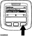
From the MAIN MENU, use the center button to scroll down to the SETTINGS MENU and press the right button (Figure 37).
-
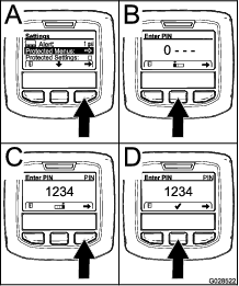
In the SETTINGS MENU, use the center button to scroll down to the PROTECTED MENU and press the right button (Figure 38A).
-
To enter the PIN code, press the center button until the correct first digit appears, then press the right button to move on to the next digit (Figure 38B and Figure 38C). Repeat this step until the last digit is entered and press the right button once more.
-
Press the middle button to enter the PIN code (Figure 38D).
Wait until the red indicator light of the InfoCenter illuminates.
Note: If the InfoCenter accepts the PIN code and the protected menu is unlocked, the word “PIN” displays in the upper right corner of the screen.
Note: Rotate the key switch to the OFF position and then to the ON position locks the protected menu.
You can view and change the settings in the Protected Menu. Once you access the Protected Menu, scroll down to Protect Settings option. Use the right button to change the setting. Setting the Protect Settings to OFF allows you to view and change the settings in the Protected Menu without entering the PIN code. Setting the Protect Settings to ON hides the protected options and requires you to enter the PIN code to change the setting in the Protected Menu. After you set the PIN code, rotate the key switch OFF and back to the ON position to enable and save this feature.
Setting the Auto Idle
-
In the Settings Menu, scroll down to Auto Idle.
-
Press the right button to change the auto idle time between Off, 8S, 10S, 15S, 20S, and 30S.
Setting the Blade Count
-
In the Settings Menu, scroll down to Blade Count
-
Press the right button to change the blade count between 5, 8, or 11 blades.
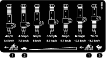
Setting the Mow Speed
-
In the Settings Menu, scroll down to Mow Speed.
-
Press the right button to select mow speed.
-
Use the center and right button to select the appropriate mow speed set on the mechanical mow-speed limiter on the traction pedal.
-
Press the left button to exit mow speed and save the setting.
Setting the Height of Cut (HOC)
-
In the Settings Menu, scroll down to HOC.
-
Press the right button to select HOC.
-
Use the center and right button to select the appropriate HOC setting.
Note: If the exact setting is not displayed, select the nearest HOC setting from the list displayed.
-
Press the left button to exit HOC and save the setting.
Setting the Front and Rear Reel Speeds
Although the front and rear reel speeds are calculated by inputting the number of blades, mow speed and HOC into the InfoCenter, you can manually change the setting to accommodate different mowing conditions.
-
Scroll down to the F Reel RPM, R Reel RPM, or both.
-
Press the right button to change the reel speed value. As the speed setting changes, the display continues to show the calculated reel speed based on blade count, mow speed, and HOC previously entered, but the new speed value also displays.
Note: Specifications and design are subject to change without notice.
Traction Unit Specifications
| Width of cut, 27-inch cutting units | 307 cm (121 inches) |
| Width of cut, 32-inch cutting units | 320 cm (126 inches) |
| Overall width, 27-inch cutting units down | 345 cm (136 inches) |
| Overall width, 32-inch cutting units down | 358 cm (141 inches) |
| Overall width, cutting units up (transport) | 239 cm (94 inches) |
| Overall length | 370 cm (146 inches) |
| Height with ROPS | 220 cm (87 inches) |
| Track width, front | 229 cm (90 inches) |
| Track width, rear | 141 cm (55.5 inches) |
| Wheelbase | 171 cm (67.5 inches) |
| Net weight (with no cutting units and no fluids) | 1574 kg (3,470 lb) |
Attachments/Accessories
A selection of Toro approved attachments and accessories is available for use with the machine to enhance and expand its capabilities. Contact your Authorized Service Dealer or authorized Toro distributor or go to www.Toro.com for a list of all approved attachments and accessories.
To ensure optimum performance and continued safety certification of the machine, use only genuine Toro replacement parts and accessories. Replacement parts and accessories made by other manufacturers could be dangerous, and such use could void the product warranty.
Operation
Note: Determine the left and right sides of the machine from the normal operating position.
Before Operation
Before Operation Safety
General Safety
-
Never allow children or untrained people to operate or service the machine. Local regulations may restrict the age of the operator. The owner is responsible for training all operators and mechanics.
-
Become familiar with the safe operation of the equipment, operator controls, and safety signs.
-
Before you leave the operator’s position, do the following:
-
Park the machine on a level surface.
-
Disengage and lower the cutting units.
-
Engage the parking brake.
-
Shut off the engine and remove the key.
-
Wait for all movement to stop.
-
Allow the machine to cool before adjusting, servicing, cleaning, or storing it.
-
-
Know how to stop the machine and shut off the engine quickly.
-
Do not operate the machine without all guards and other safety protective devices in place and functioning properly on the machine.
-
Before mowing, always inspect the machine to ensure that the cutting units are in good working condition.
-
Inspect the area where you will use the machine and remove all objects that the machine could throw.
Fuel Safety
-
Use extreme care in handling fuel. It is flammable and its vapors are explosive.
-
Extinguish all cigarettes, cigars, pipes, and other sources of ignition.
-
Use only an approved fuel container.
-
Do not remove the fuel cap or fill the fuel tank while the engine is running or hot.
-
Do not add or drain fuel in an enclosed space.
-
Do not store the machine or fuel container where there is an open flame, spark, or pilot light, such as on a water heater or other appliance.
-
If you spill fuel, do not attempt to start the engine; avoid creating any source of ignition until the fuel vapors have dissipated.
Filling the Fuel Tank
Fuel Tank Capacity
83 L (22 US gallons)
Fuel Specification
Important: Use only ultra-low sulphur diesel fuel. Fuel with higher rates of sulfur degrades the diesel oxidation catalyst (DOC), which causes operational problems and shortens the service life of engine components.Failure to observe the following cautions may damage the engine.
-
Never use kerosene or gasoline instead of diesel fuel.
-
Never mix kerosene or used engine oil with the diesel fuel.
-
Never keep fuel in containers with zinc plating on the inside.
-
Do not use fuel additives.
Petroleum Diesel
Cetane rating: 45 or higher
Sulfur content: Ultra-low sulfur (<15 ppm)
| Diesel fuel specification | Location |
| ASTM D975 | USA |
| No. 1-D S15 | |
| No. 2-D S15 | |
| EN 590 | European Union |
| ISO 8217 DMX | International |
| JIS K2204 Grade No. 2 | Japan |
| KSM-2610 | Korea |
-
Use only clean, fresh diesel fuel or biodiesel fuels.
-
Purchase fuel in quantities that can be used within 180 days to ensure fuel freshness.
Use summer-grade diesel fuel (No. 2-D) at temperatures above -7°C (20°F) and winter-grade fuel (No. 1-D or No. 1-D/2-D blend) below that temperature.
Note: Use of winter-grade fuel at lower temperatures provides lower flash point and cold flow characteristics which eases starting and reduces fuel filter plugging.Using summer-grade fuel above -7°C (20°F) contributes toward longer fuel pump life and increased power compared to winter-grade fuel.
Biodiesel
This machine can also use a biodiesel blended fuel of up to B20 (20% biodiesel, 80% petroleum diesel).
Sulfur content: Ultra-low sulfur (<15 ppm)
Biodiesel fuel specification: ASTM D6751 or EN14214
Blended fuel specification: ASTM D975, EN590, or JIS K2204
Important: The petroleum diesel portion must be ultra-low sulfur.
Observe the following precautions:
-
Biodiesel blends may damage painted surfaces.
-
Use B5 (biodiesel content of 5%) or lesser blends in cold weather.
-
Monitor seals, hoses, gaskets in contact with fuel as they may be degraded over time.
-
Fuel filter plugging may be expected for a time after converting to biodiesel blends.
-
Contact your authorized Toro distributor if you wish for more information on biodiesel.
Adding Fuel
-
Park the machine on a level surface, lower the cutting units, shut off the engine, and remove the key.
-
Using a clean rag, clean the area around the fuel-tank cap.
-
Remove the cap from the fuel tank (Figure 39).
-
Fill the tank until the level is to the bottom of the filler neck with the specified fuel.
-
Install the fuel-tank cap tightly.
Note: If possible, fill the fuel tank after each use. Filling the fuel tank minimizes condensation inside the tank.
Performing Daily Maintenance
Before starting the machine each day, perform the Each Use/Daily procedures listed in .
Checking the Interlock Switches
| Maintenance Service Interval | Maintenance Procedure |
|---|---|
| Before each use or daily |
|
Caution
If safety interlock switches are disconnected or damaged, the machine could operate unexpectedly, causing personal injury.
-
Do not tamper with the interlock switches.
-
Check the operation of the interlock switches daily and replace any damaged switches before operating the machine.
Important: If your machine fails any of the interlock switch checks, contact your authorized Toro distributor.
Preparing the Machine
-
Drive the machine slowly to an open area.
-
Lower the cutting units, shut off the engine, and engage the parking brake.
Checking the Traction Pedal Start-Interlock
-
Sit in the operator’s seat.
-
Engage the parking brake.
-
Press the PTO switch to the DISENGAGE position.
-
Press the traction pedal.
-
Rotate the key to the START position.
Note: The starter should not crank the engine with the traction pedal pressed.
Checking the PTO-Start Interlock
-
Sit in the operator’s seat.
-
Press the PTO switch to the ENGAGE position.
-
Start the engine.
Note: The engine should not start with the PTO switch in the ENGAGE position.
Checking the PTO-Run Interlock
-
Sit in the operator’s seat.
-
Press the PTO switch to the DISENGAGE position.
-
Start the engine.
-
Rise from the seat.
-
Press the PTO switch to the ENGAGE position.
Note: The PTO should not run when you are out of the operator’s seat.
Checking the Parking Brake and Traction Pedal Run-Interlock
-
Sit in the operator’s seat.
-
Engage the parking brake.
-
Press the PTO switch to the DISENGAGE position.
-
Keep your foot off the traction pedal.
-
Start the engine.
-
Press the traction pedal.
Note: The engine should shut off when the parking brake is engaged and the traction pedal is pressed.
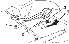
Adjusting the Seat
Seat Armrest Adjusting Knob
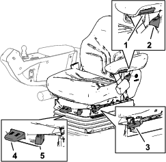
Rotate the knob to adjust the seat armrest angle (Figure 40).
Seat Back Adjusting Lever
Move the lever to adjust the seat back angle (Figure 40).
Fore and Aft Adjusting Lever
Pull out on the lever to slide the seat fore or aft (Figure 40).
Weight Adjusting Lever
Adjust the seat to your weight (Figure 40). Pull up on the lever to increase the air pressure and push down to decrease the air pressure. The proper adjustment is attained when the weight gauge is in the green region.
Weight gauge
The weight gauge indicates when the seat is adjusted to the weight of the operator (Figure 40). Height adjustment is made by positioning the suspension within the range of the green region.
During Operation
During Operation Safety
General Safety
-
The owner/operator can prevent and is responsible for accidents that may cause personal injury or property damage.
-
Wear appropriate clothing, including eye protection; long trousers; substantial, slip-resistant footwear; and hearing protection. Tie back long hair and do not wear loose clothing or loose jewelry.
-
Do not operate the machine while ill, tired, or under the influence of alcohol or drugs.
-
Use your full attention while operating the machine. Do not engage in any activity that causes distractions; otherwise, injury or property damage may occur.
-
Before you start the engine, ensure that all drives are in neutral, the parking brake is engaged, and you are in the operating position.
-
Do not carry passengers on the machine and keep bystanders and children out of the operating area.
-
Operate the machine only in good visibility to avoid holes or hidden hazards.
-
Avoid mowing on wet grass. Reduced traction could cause the machine to slide.
-
Keep your hands and feet away from the cutting units.
-
Look behind and down before backing up to be sure of a clear path.
-
Use care when approaching blind corners, shrubs, trees, or other objects that may obscure your vision.
-
Stop the cutting units whenever you are not mowing.
-
Slow down and use caution when making turns and crossing roads and sidewalks with the machine. Always yield the right-of-way.
-
Operate the engine only in well-ventilated areas. Exhaust gases contain carbon monoxide, which is lethal if inhaled.
-
Do not leave a running machine unattended.
-
Before you leave the operator’s position, do the following:
-
Park the machine on a level surface.
-
Disengage and lower the cutting units.
-
Engage the parking brake.
-
Shut off the engine and remove the key.
-
Wait for all movement to stop.
-
Allow the machine to cool before adjusting, servicing, cleaning, or storing it.
-
-
Operate the machine only in good visibility and appropriate weather conditions. Do not operate the machine when there is the risk of lightning.
Rollover Protection System (ROPS) Safety
-
Do not remove any of the ROPS components from the machine.
-
Ensure that the seat belt is attached and that you can release it quickly in an emergency.
-
Always wear your seat belt.
-
Check carefully for overhead obstructions and do not contact them.
-
Keep the ROPS in safe operating condition by thoroughly inspecting it periodically for damage and keeping all the mounting fasteners tight.
-
Replace all damaged ROPS components. Do not repair or alter them.
Machines with a Foldable Roll Bar
-
Always use the seat belt with the roll bar in the raised position.
-
The ROPS is an integral safety device. Keep a folding roll bar in the raised and locked position, and use the seat belt when operating the machine with the roll bar in the raised position.
-
Lower a folding roll bar temporarily only when necessary. Do not wear the seat belt when the roll bar is folded down.
-
Be aware that there is no rollover protection when a folded roll bar is in the down position.
-
Check the area that you will be mowing and never fold down a folding roll bar in areas where there are slopes, drop-offs, or water.
Slope Safety
-
Slopes are a major factor related to loss of control and rollover accidents, which can result in severe injury or death. You are responsible for safe slope operation. Operating the machine on any slope requires extra caution.
-
Evaluate the site conditions to determine if the slope is safe for machine operation, including surveying the site. Always use common sense and good judgment when performing this survey.
-
Review the slope instructions, listed below, for operating the machine on slopes. Before you operate the machine, review the site conditions to determine whether you can operate the machine in the conditions on that day and at that site. Changes in the terrain can result in a change in slope operation for the machine.
-
Avoid starting, stopping, or turning the machine on slopes. Avoid making sudden changes in speed or direction. Make turns slowly and gradually.
-
Do not operate a machine under any conditions where traction, steering, or stability is in question.
-
Remove or mark obstructions such as ditches, holes, ruts, bumps, rocks, or other hidden hazards. Tall grass can hide obstructions. Uneven terrain could overturn the machine.
-
Be aware that operating the machine on wet grass, across slopes, or downhill may cause the machine to lose traction.
-
Use extreme caution when operating the machine near drop-offs, ditches, embankments, water hazards, or other hazards. The machine could suddenly roll over if a wheel goes over the edge or the edge caves in. Establish a safety area between the machine and any hazard.
-
Identify hazards at the base of the slope. If there are hazards, mow the slope with a pedestrian-controlled machine.
-
If possible, keep the cutting units lowered to the ground while operating on slopes. Raising the cutting units while operating on slopes can cause the machine to become unstable.
-
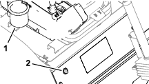
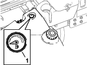
Fuel Gauge
Use the fuel gauge (Figure 41) at the top of the tank to determine the fuel level.
Using the Engine-Speed Switch
The engine-speed switch has 2 modes to change the engine speed.
-
Momentarily tapping the switch increases or decreases the engine speed in 100-rpm increments.
-
Pressing and holding the switch down moves the engine speed directly to high or low idle, depending on which side of the switch you press.
Starting the Engine
Important: Bleed the fuel system if any of the following situations have occurred:
-
The engine has shut off because the machine ran out of fuel.
-
Maintenance was performed on the fuel system components.
-
Sit in the operator’s seat, engage the parking brake, and ensure that your foot is off the traction pedal.
-
Press the engine-speed switch to the LOW IDLE position.
-
Turn the key to the RUN position.
Note: The glow-plug indicator displays in the InfoCenter.
-
When the glow indicator shuts off, turn the key to the START position.
Important: Do not run the starter motor more than 15 seconds at a time, or premature starter failure may result. If the engine fails to start after 15 seconds, turn the key to the OFF position, check the controls and procedures, wait 15 additional seconds, and repeat the starting procedure.When the temperature is less than -7°C (20°F), the starter motor can be run for 30 seconds on then 60 seconds off for 2 attempts.
-
When the engine starts, release the key.
-
Adjust the engine speed.
Shutting Off the Engine
-
Park the machine on a level surface.
-
Press the PTO switch to the DISENGAGE position.
-
Press the engine-speed switch to the LOW IDLE position.
-
Engage the parking brake.
-
Lower the cutting units.
Important: Lowering the cutting units relieves the hydraulic load from the system, prevents wear on system parts, and prevents accidental lowering of the cutting units.
-
If the machine was run at full-load operation, allow the engine to idle for 5 minutes.
Important: Idling the engine for 5 minutes allows the turbocharger to cool down before shutting off the engine. Failure to do so may lead to turbocharger damage.
-
Rotate the key to OFF and remove the key.
-
Wait for all moving parts to stop.
Locking the Cutting-Unit Pivot
Cutting Grass on a Hill Side
Lock the cutting-unit pivots to prevent the cutting units from rotating downhill when cutting across the face of a hill.
-
Secure the carrier frame of the cutting unit to the pivot yoke with the snapper pin as shown in Figure 43.
-
Repeat step 1 at the other cutting units.
Cutting Grass with the Machine
-
Drive the machine to the job site and align the machine outside the cutting area for the first cutting pass.
-
Ensure that the PTO switch is set to the DISENGAGE position (Figure 44).
-
Use your foot to move the lever for the mow-speed limiter forward, to the MOW position (Figure 45).
-
Press the throttle-speed switch to set the engine speed to HIGH IDLE.
-
Press the PTO switch to the ENGAGE position.
-
Begin driving the machine into the cutting area, and move the lower mow/raise control lever forward.
Note: The cutting units start running as they lower. The front cutting units are timed to lower before the rear cutting units
Note: Cutting grass at a rate that loads the engine promotes DPF regeneration.
-
When you complete the mowing pass, move the lever for the mow-speed limiter backward to lift the cutting units.
-
Perform a tear-shaped turn to quickly line up for your next pass.
Driving the Machine in Transport Mode
-
Press the PTO switch to the DISENGAGE position (Figure 46).
-
Move the lower mow/raise control lever rearward to raise the cutting units (transport position).
-
Move the lever for the mow-speed limiter rearward to the TRANSPORT position (Figure 47).
-
Press the traction pedal to drive the machine.
Important: Be careful when driving between objects so that you do not accidentally damage the machine or cutting units. Use extra care when operating the machine on slopes. Drive slowly and avoid sharp turns on slopes to prevent a rollover.
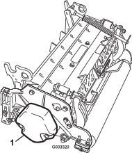
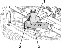
Adjusting the Turf-Compensation Spring
The turf-compensation spring (Figure 48) transfers the weight from the front roller to the rear roller. This helps to reduce a wave pattern in the turf, also known as marcelling or bobbing.
Important: Make spring adjustments with the cutting unit mounted to the traction unit, pointing straight ahead, and lowered to the shop floor.
-
Make sure that the hairpin is installed in the rear hole in the spring rod (Figure 48).
Note: When servicing the cutting unit, move the hairpin to the spring-rod hole next to the turf-compensation spring.
-
Tighten the hex nuts on the front end of the spring rod until the compressed length of the spring is 15.9 cm (6.25 inches); refer to Figure 48.
Note: When operating on rough terrain decrease the spring length by 13 mm (1/2 inch). Ground following will be slightly decreased.
Note: The turf compensation setting will need to be reset if the HOC setting or the Aggressiveness of Cut setting is changed.
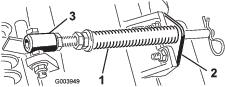
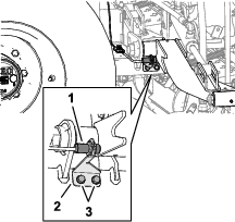
Adjusting the Cutting-Unit Counterbalance
Rear Cutting Units
Caution
The springs are under tension and could cause personal injury.
Use caution when adjusting the springs.
You can adjust the amount of counterbalance force applied to the rear cutting-units to help compensate for different turf conditions, and to maintain a uniform height of cut in rough conditions or in areas of thatch buildup.
You adjust counterbalance force of each torsion spring to 1 of 4 settings. Each increment increases or decreases the counterbalance force on the cutting unit by 2.3 kg (5 lb).
Note: To remove all counterbalance force, position the long leg of the torsion spring below the capscrew, washer, spacer, and locknut.
-
Park the machine on a level surface, lower the cutting units, engage the parking brake, shut off the engine, and remove the key.
-
Insert a tube or similar object over the long leg of the spring, and lift the spring leg to relieve pressure on the spacer (Figure 49).
Note: Have another person help by lifting and lowering the spring leg.
-
While holding the spring, remove the bolt, washer, and locknut from the lift plate (Figure 49).
-
Align the spring leg above the desired hole location.
-
Install the capscrew, washer, spacer, and locknut at the hole location.
-
Slowly lower the spring leg onto the spacer.
-
Repeat the steps through 5 at the rear cutting unit-lift arm.
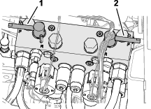
Adjusting the Cutting Unit-Turnaround Height
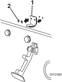
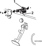
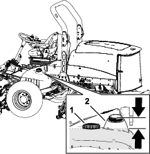
The lift-arm switch (Figure 37) is located behind the right, front lift arm (cutting unit #5).
-
Park the machine on a level surface, lower the cutting units, engage the parking brake, shut off the engine, and remove the key.
-
Loosen the 2 flange-head screws that secure the switch bracket to the carrier frame for the front cutting unit-lift arms.
-
Move the switch bracket as follows:
-
To increase the cutting unit-turnaround height, move the bracket up.
-
To decrease the cutting unit-turnaround height, move the bracket down.
-
-
Tighten the 2 flange-head screws.
Folding the Roll Bar
-
Keep all nuts, bolts, and screws correctly torqued ensure that the equipment is in safe working condition.
-
Replace worn or damaged parts for safety.
-
Ensure that the seat belt and mountings are in safe working order.
-
Wear the seat belt when the roll bar is raised and no seat belt when the roll bar is lowered.
You can fold the roll bar down to allow access into areas with restricted height.
Warning
The machine does not have a rollover protection system (ROPS) when the roll bar is folded down and should not be considered a ROPS.
Do not wear a seatbelt when the roll bar is lowered.
Warning
When lowering and raising the roll bar, your fingers may get pinched between the machine and the roll bar.
Use caution when lowering and raising the roll bar to prevent your fingers from getting pinched between the machine and the roll bar.
Warning
The roll bar is an integral safety device. It does not protect you from injury or even death from a rollover unless it is secured in the raised position and you are wearing the seat belt.
-
Keep the roll bar in the raise position whenever you operate the machine.
-
Lower the roll bar temporarily only when necessary, then secure it in the raised position as soon as possible before continuing operation.
Important: The roll bar is an integral safety device. Keep the roll bar in the raised position when operating the mower. Lower the roll bar temporarily only when absolutely necessary.
-
Park the machine on a level surface, lower the cutting units, engage the parking brake, shut off the engine, and remove the key.
-
Remove the lynch pins that secure the roll-bar pins at each side of the roll bar (Figure 51).
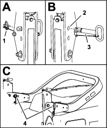
-
Support the weight of the upper roll-bar tube while removing roll-bar pins from the pivot brackets.
-
Carefully lower the upper roll-bar tube until it rests on the stops.
-
Insert the roll-bar pins into the lower holes in the pivot brackets, and secure the roll-bar pins to the brackets with the lynch pins.
Raising the Rollbar
Warning
The ROPS protection system may not be effective if the roll-bar pins are loose, which may cause serious injury or even death in the event of a rollover.
When the roll bar is in the raised position, you must install both roll-bar pins and both lynch pins to ensure full ROPS protection.
-
Park the machine on a level surface, lower the cutting units, engage the parking brake, shut off the engine, and remove the key.
-
Remove the lynch pins that secure the roll-bar pins at each side of the roll bar (Figure 52).
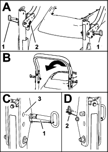
-
Removing roll-bar pins from the pivot brackets.
-
Carefully lift the upper roll-bar tube until the holes in the pivot bracket align with the holes in the lower roll-bar tube.
-
Insert the roll-bar pins into the holes in the pivot bracket and lower roll-bar tube.
-
Secure the roll-bar pins to the brackets and lower roll-bar tubes with the lynch pins.
Diesel Particulate Filter Regeneration
The diesel particulate filter (DPF) is part of the exhaust system. The diesel-oxidation catalyst of the DPF reduces harmful gasses and the soot filter removes soot from the engine exhaust.
The DPF regeneration process uses heat from the engine exhaust to incinerate the soot accumulated on the soot filter, converting the soot to ash, and clears the channels of the soot filter so that filtered engine exhaust flows out the DPF.
The engine computer monitors the accumulation of soot by measuring the back pressure in the DPF. If the back pressure is too high, soot is not incinerating in the soot filter through normal engine operation. To keep the DPF clear of soot, remember the following:
-
Passive regeneration occurs continuously while the engine is running—run the engine at full engine speed when possible, to promote DPF regeneration.
-
If the back pressure in the DPF is too high or a reset regeneration has not occurred for 100 hours, the engine computer signals you through the InfoCenter when reset regeneration is running.
-
Allow the reset regeneration process to complete before shutting off the engine.
Operate and maintain your machine with the function of the DPF in mind. Engine load at high idle (full throttle) engine speed generally produces adequate exhaust temperature for DPF regeneration.
Important: Minimize the amount of time that you idle the engine or operate the engine at low-engine speed to help reduce the accumulation of soot in the soot filter.
DPF Soot Accumulation
-
Over time, the diesel particulate filter accumulates soot in the soot filter. The computer for the engine monitors the soot level in the DPF.
-
When enough soot accumulates, the computer informs you that it is time to regenerate the DPF.
-
DPF regeneration is a process that heats the DPF to convert the soot to ash.
-
In addition to the warning messages, the computer reduces the power produced by the engine at different soot-accumulation levels.
| Indication Level | Fault Code | Engine Power Rating | Recommended Action |
| Level 1: Engine Warning |
 | The computer de-rates the engine power to 85%. | Perform a parked regeneration as soon as possible; refer to Parked or Recovery Regeneration. |
| Level 2: Engine Warning |
 | The computer de-rates the engine power to 50%. | Perform a recovery regeneration as soon as possible; refer to Parked or Recovery Regeneration. |
DPF Ash Accumulation
-
The lighter ash is discharged through the exhaust system; the heavier ash collects in the soot filter.
-
Ash is a residue of the regeneration process. Over time, the diesel particulate filter accumulates ash that does not discharge with the engine exhaust.
-
The computer for the engine calculates the amount of ash accumulated in the DPF.
-
When enough ash accumulates, the engine computer sends information to the InfoCenter in the form of an engine fault to indicate the accumulation of ash in the DPF.
-
The fault messages indicate that it is time to service the DPF.
-
In addition to the warnings, the computer reduces the power produced by the engine at different ash-accumulation levels.
| Indication Level | Fault Code | Engine Speed Reduction | Engine Power Rating | Recommended Action |
|---|---|---|---|---|
| Level 1: Engine Warning |
 | None | The computer de-rates the engine power to 85%. | Service the DPF; refer to Servicing the Diesel-Oxidation Catalyst (DOC) and the Soot Filter |
| Level 2: Engine Warning |
| None | The computer de-rates the engine power to 50%. | Service the DPF; refer to Servicing the Diesel-Oxidation Catalyst (DOC) and the Soot Filter |
| Level 3: Engine Warning |
 | Engine speed at maximum torque + 200 rpm | The computer de-rates the engine power to 50%. | Service the DPF; refer to Servicing the Diesel-Oxidation Catalyst (DOC) and the Soot Filter |
Types of Diesel Particulate Filter Regeneration
| Type of Regeneration | Conditions that cause DPF regeneration | DPF description of operation |
|---|---|---|
| Passive | Occurs during normal operation of the machine at high-engine speed or high-engine load | • The InfoCenter does not display an icon indicating passive regeneration. |
| • During passive regeneration, the DPF processes high-heat exhaust gasses, oxidizing harmful emissions, and burning soot to ash. | ||
| Refer to Passive DPF Regeneration. | ||
| Assist | Occurs because of low-engine speed, low-engine load, or after the computer detects the DPF is becoming obstructed with soot | • The InfoCenter does not display an icon indicating assist regeneration. |
| • During assist regeneration, the engine computer adjusts the engine settings to raise the exhaust temperature. | ||
| Refer to Assist DPF Regeneration. | ||
| Reset | Occurs every 100 hours | • When the high exhaust-temperature icon  is displayed in the InfoCenter,
a regeneration is in progress. is displayed in the InfoCenter,
a regeneration is in progress. |
| Also occurs after assist regeneration only if the computer detects that assist regeneration did not sufficiently reduce the soot level | ||
| • During reset regeneration, the engine computer adjusts the engine settings to raise the exhaust temperature. | ||
| Refer to Reset Regeneration. |
| Type of Regeneration | Conditions that cause DPF regeneration | DPF description of operation |
|---|---|---|
| Parked | Occurs because the computer detects back pressure in the DPF due to soot buildup | • When the reset-standby/parked
or recovery regeneration icon  or ADVISORY #188 displays
in the InfoCenter, a regeneration is requested. or ADVISORY #188 displays
in the InfoCenter, a regeneration is requested. |
| Also occurs because the operator initiates a parked regeneration | ||
| May occur because you set the InfoCenter to inhibit reset regeneration and continued operating the machine, adding more soot when the DPF already needs a reset regeneration | • Perform the parked regeneration as soon as possible to avoid needing a recovery regeneration. | |
| May result from using the incorrect fuel or engine oil | • A parked regeneration requires 30 to 60 minutes to complete. | |
| • You must have at least a 1/4 tank of fuel in the tank. | ||
| • You must park the machine to perform a parked regeneration. | ||
| Refer to Parked or Recovery Regeneration. | ||
| Recovery | Occurs because the operator ignored requests for a parked regeneration and continued operating the machine, adding more soot to the DPF | • When the reset-standby/parked or recovery
regeneration icon or ADVISORY #190 displays
in the InfoCenter, a recovery regeneration is requested. |
| • A recovery regeneration requires up to 3 hours to complete. | ||
| • You must have at least a 1/2 tank of fuel in the machine. | ||
| • You must park the machine to perform a recovery regeneration. | ||
| Refer to Parked or Recovery Regeneration. |
Accessing the DPF Regeneration Menus
Accessing the DPF Regeneration Menus
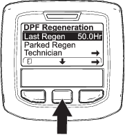
Time Since Last Regeneration
Access the DPF Regeneration menu, press the center button to scroll down to the LAST REGEN field (Figure 59).
Use the LAST REGEN field to determine how many hours you have run the engine since the last reset, parked, or recovery regeneration.
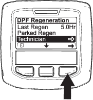
Technician Menu
Important: For operating convenience, you may decide to perform a parked regeneration before the soot load reaches 100%, provided the engine has run more than 50 hours since the last successful reset, parked, or recovery regeneration.
Use the technician menu to view the current state of engine regeneration control and view the reported soot level.
Access the DPF Regeneration menu, press the center button to scroll down to the TECHNICIAN option, and press the right button to select the Technician entry (Figure 60).
-
Use the DPF operation table to understand the current state of DPF operation (Figure 61).

.
DPF Operation Table
State Description Normal The DPF is in normal-operating mode—passive regeneration. Assist Regen The engine computer is performing an assist regeneration. Reset Stby The engine computer is trying to run a reset regeneration, but 1 of the following conditions prevent regeneration: The regen inhibit setting is set to ON. The exhaust temperature is too low for regeneration. Reset Regen The engine computer is running a reset regeneration. Parked Stby The engine computer is requesting that you run a parked regeneration. Parked Regen You initiated a parked regeneration request and the engine computer is processing the regeneration. Recov. Stby The engine computer is requesting that you run a recovery regeneration. Recov. Regen You initiated a recovery regeneration request and the engine computer is processing the regeneration. -
View the soot load which is measured as the percentage of soot in the DPF(Figure 62); refer to the soot-load table.
Note: The soot load value varies as the machine is operated and DPF regeneration occurs.

Soot-Load Table
Important Soot Load Values Regeneration State 0% to 5% Minimum soot load range 78% The engine computer performs an assist regeneration. 100% The engine computer automatically requests a parked regeneration. 122% The engine computer automatically requests a recovery regeneration.
Passive DPF Regeneration
-
Passive regeneration occurs as part of normal engine operation.
-
While operating the machine, run the engine at full-engine speed and high load when possible, to promote DPF regeneration.
Assist DPF Regeneration
-
The engine computer adjusts engine settings to raise the exhaust temperature.
-
While operating the machine, run the engine at full engine speed and high load when possible, to promote DPF regeneration.
Reset Regeneration
Caution
The exhaust temperature is hot (approximately 600°C (1,112°F) during DPF regeneration. Hot exhaust gas can harm you or other people.
-
Never operate the engine in an enclosed area.
-
Make sure that there are no flammable materials around the exhaust system.
-
Never touch a hot exhaust system component.
-
Never stand near or around the exhaust pipe of the machine.
-
The high exhaust-temperature icon
displays in the InfoCenter
(Figure 63). -
The engine computer adjusts engine settings to raise the exhaust temperature.
Important: The high exhaust-temperature icon indicates that the exhaust temperature discharged from of your machine may be hotter than during regular operation.
-
While operating the machine, run the engine at full engine speed and high load when possible, to promote DPF regeneration.
-
The icon displays in the InfoCenter while the reset regeneration is processing.
-
Whenever possible, do not shut off the engine or reduce engine speed while the reset regeneration is processing.
Important: Whenever possible, allow the machine to complete the reset regeneration process before shutting off the engine.
Periodic Reset Regeneration
If the engine has not completed a successful Reset, Parked, or Recovery regeneration in the previous 100 hours of engine operation, the engine computer will attempt to perform a reset regeneration.
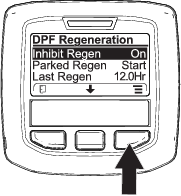
Setting the Inhibit Regen
Reset Regeneration Only

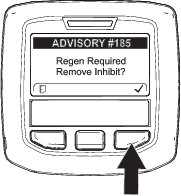
Note: If you set the InfoCenter to inhibit regeneration, the InfoCenter displays ADVISORY #185 (Figure 64) every 15 minutes while the engine requests a reset regeneration.
A reset regeneration produces the elevated engine exhaust. If you are operating the machine around trees, brush, tall grass, or other temperature-sensitive plants or materials, you can use the Inhibit Regen setting to prevent the engine computer from performing a reset regeneration.
Important: When you shut off the engine and start it again, the inhibit regen setting defaults to OFF.

Allowing a Reset Regeneration
The InfoCenter displays the high exhaust-temperature icon when the reset regeneration
is in process.
Note: If INHIBIT REGEN is set to ON, the InfoCenter displays ADVISORY #185 (Figure 67). Press button 3 to set inhibit regeneration setting to OFF and continue with the reset regeneration.
Note: If the engine exhaust temperature is too low, the InfoCenter displays ADVISORY #186 (Figure 68) to inform you to set the engine to full throttle (high idle).

Note: When the reset regeneration completes, the high exhaust-temperature disappears from the InfoCenter
screen.
Parked or Recovery Regeneration
-
When the engine computer requests either a parked regeneration or a recovery regeneration, the regeneration request icon (Figure 69) displays in the InfoCenter.
-
The machine does not automatically perform a parked regeneration or a recovery regeneration, you must run the regeneration through the InfoCenter.
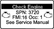
Parked Regeneration Messages
When a parked regeneration is requested by the engine computer the following messages display in the InfoCenter:
-
Engine warning SPN 3720, FMI 16 (Figure 70)
-
Parked regeneration required ADVISORY #188 (Figure 71)
Note: Advisory #188 displays every 15 minutes.

-
If you do not perform a parked regeneration within 2 hours, the InfoCenter displays parked regeneration required—power takeoff disabled ADVISORY #189 (Figure 72).
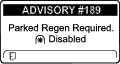
Important: Perform a parked regeneration to restore the PTO function; refer to Preparing to Perform a Parked or Recovery Regeneration and Performing a Parked or Recovery Regeneration.
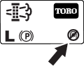
Note: The Home screen displays the PTO disabled Icon (Figure 73).
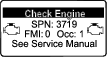
Recovery Regeneration Messages
When a recovery regeneration is requested by the engine computer, the following messages display in the InfoCenter:
-
Engine warning SPN 3719, FMI 0 (Figure 74)
-
Recovery regeneration required—power takeoff disabled ADVISORY #190 (Figure 75)
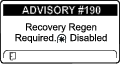
Important: Perform a recovery regeneration to restore the PTO function; refer to Preparing to Perform a Parked or Recovery Regeneration and Performing a Parked or Recovery Regeneration.
Note: The Home screen displays the PTO disabled Icon; refer to Figure 73 in Parked Regeneration Messages.
DPF Status-Limitation
-
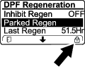
If the engine computer requests a recovery regeneration or is processing a recovery regeneration and you scroll down to the PARKED REGEN option, parked regeneration locks and the lock icon (Figure 76) appears in the lower right corner of the InfoCenter.
-
If the engine computer has not requested a recovery regeneration and you scroll down to the RECOVERY REGEN option, the recovery regeneration locks and the lock icon (Figure 77) appears in the lower right corner of the InfoCenter.
Preparing to Perform a Parked or Recovery Regeneration
-
Ensure that the machine has fuel in the tank for the type of regeneration you are performing:
-
Parked Regeneration: Ensure that you have 1/4 tank of fuel before performing the parked regeneration.
-
Recovery Regeneration: Ensure that you have 1/2 tank of fuel before performing the recovery regeneration.
-
-
Move the machine outside to an area away from combustible materials.
-
Park the machine on a level surface.
-
Ensure that the traction control or motion-control levers are in the NEUTRAL position.
-
If applicable, shut off the PTO, and lower the cutting units or accessories.
-
Engage the parking brake.
-
Set the throttle to the low IDLE position.
Performing a Parked or Recovery Regeneration
Caution
The exhaust temperature is hot (approximately 600°C (1,112°F) during DPF regeneration. Hot exhaust gas can harm you or other people.
-
Never operate the engine in an enclosed area.
-
Make sure that there are no flammable materials around the exhaust system.
-
Never touch a hot exhaust system component.
-
Never stand near or around the exhaust pipe of the machine.
Important: The computer of the machine cancels DPF regeneration if you increase the engine speed from low idle or release the parking brake.
-
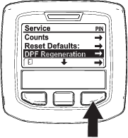
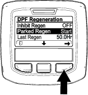
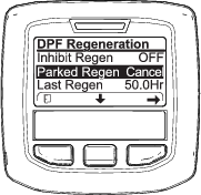
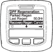
Access the DPF Regeneration menu, press the center button to scroll down to either the PARKED REGEN START option or the RECOVERY REGEN START option (Figure 78), and press the right button to select the start the regeneration (Figure 78).

-
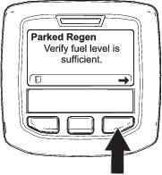
At the VERIFY FUEL LEVEL screen, verify that you have 1/4 tank of fuel if you are performing the parked regeneration or 1/2 tank of fuel if you are performing the recovery regeneration, and press the right button to continue (Figure 79).

-
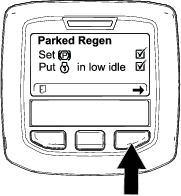
At the DPF checklist screen, verify that the parking brake is engaged and that the engine speed is set to low idle (Figure 80).

-
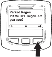
At the INITIATE DPF REGEN screen, press the right button to continue (Figure 81).

-
The InfoCenter displays the INITIATING DPF REGEN message (Figure 82).


-
The InfoCenter displays the time to complete message (Figure 83).


-
The engine computer checks the engine state and fault information. The InfoCenter may display the following messages found in the table that follows:
Check Message and Corrective Action Table

Corrective Action: Exit the regeneration menu and run the machine until the time since last regeneration is greater than 50 hours; refer to Time Since Last Regeneration. 

Corrective Action: Troubleshoot the engine fault and retry DPF regeneration. 

Corrective Action: Start and run the engine. 

Corrective Action: Run the engine to warm the coolant temperature to 60°C (140°F). 

Corrective Action: Change the engine speed to low idle. 

Corrective Action: Troubleshoot the engine computer condition and retry DPF regeneration. -
The InfoCenter displays the home screen and the regeneration acknowledge icon (Figure 84) appears in the lower right corner of the screen as the regeneration processes.
Note: While the DPF regeneration runs, the InfoCenter displays the high exhaust-temperature icon
. -
When the engine computer completes a parked or recovery regeneration, the InfoCenter displays ADVISORY #183 (Figure 85). Press the left button to exit to the home screen.
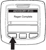
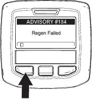
Note: If the regeneration fails to complete, the InfoCenter displays Advisory #184 (Figure 85). Press the left button to exit to the home screen.
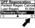
Canceling a Parked or Recovery Regeneration
Use the Parked Regen Cancel or Recovery Regen Cancel setting to cancel a running parked or recovery regeneration process.
Operating Tips
Becoming Familiar with the Machine
Before mowing grass, practice operating the machine in an open area. Start and shut off the engine. Operate in forward and reverse. Lower and raise the cutting units and engage and disengage the reels. When you feel familiar with the machine, practice operating up and down slopes at different speeds.
Understanding the Warning System
If the InfoCenter displays an operator advisory or a fault code during operation, stop the machine immediately and correct the problem before continuing operation. Serious damage could occur if you operate the machine with a malfunction.
After Operation
After Operation Safety
General Safety
-
Park the machine on a level surface.
-
Disengage and lower the cutting units.
-
Engage the parking brake.
-
Shut off the engine and remove the key.
-
Wait for all movement to stop.
-
Allow the machine to cool before adjusting, servicing, cleaning, or storing it.
-
Clean grass and debris from the cutting units, drives, mufflers, cooling screens, and engine compartment to help prevent fires. Clean up oil or fuel spills.
-
Disengage the drive to the attachment whenever you are hauling or not using the machine.
-
Maintain and clean the seat belt(s) as necessary.
-
Do not store the machine or fuel container where there is an open flame, spark, or pilot light, such as on a water heater or on other appliances.
Hauling the Machine
-
Use full-width ramps for loading the machine onto a trailer or truck.
-
Tie the machine down securely.
Identifying the Tie-Down Points
The tie-down points are in the following locations:
-
On each side of the frame under the front steps
-
The rear bumper
Pushing or Towing the Machine
Warning
While the tow bypass valve is open, the machine could unintentionally move, and injure you or bystanders.
When you are not pushing or towing the machine, engage the parking brake.
In an emergency, you can move the machine by opening tow bypass valve of the traction hydraulic pump, installing a hydraulic hose to bypass the check valve, and then pushing or towing the machine.
If you need to push or tow your machine, you may need to move it both forward and in reverse. To ensure that the drive system does not become damaged from pushing or towing, it is best to prepare the machine for both forward and reverse pushing or towing.
Preparing the Machine to Push or Tow in Reverse
Install the Reverse Tow Kit
Required Parts (purchased separately): Reverse Tow Kit, Toro Part No. 136-3620
Important: If you need to push or tow the machine in reverse, you must first bypass the check valve in the 4-wheel-drive manifold.
-
Park the machine on a level surface, engage the parking brake, lower the cutting units, shut off the engine and remove the key.
-
Loosely assemble the bypass hose and straight fittings of the reverse tow kit; refer to the Reverse Tow Kit Installation Instructions.
-
Remove the dust cap and the test fitting from the test port of the reverse traction tube.
-
Assemble the straight fitting of the bypass hose to the test port, and tighten the fitting and hose.
-
Remove the #6 hex-socket plug from the unmarked port (located between the fittings in port M8 and port P2) of the rear-traction manifold.
-
Assemble the other straight fitting of the bypass hose into the unmarked rear-traction manifold port, and tighten the fitting and hose.
-
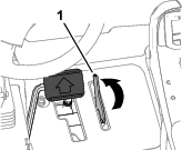
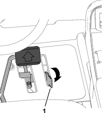
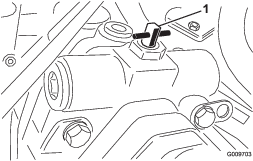
Open the tow bypass valve of the traction pump by rotating it 90° (1/4 turn) in either direction (Figure 90).
Note: Note the position of the valve when opening and closing it.
-
Push or tow the machine.
Important: Do not push or tow the machine faster than 3 to 4.8 km/h (2 to 3 mph) or for more than 0.4 km (1/4 mile), because damage to the hydraulic system may occur. The bypass valve must be open whenever you push or tow the machine.
Preparing the Machine for Operation
Remove the Reverse Tow Kit
-
Park the machine on a level surface, engage the parking brake, lower the cutting units, shut off the engine and remove the key.
-
Remove the straight fitting and bypass hose of the reverse tow kit from the test port of the reverse traction tube; refer to the Reverse Tow Kit Installation Instructions.
-
Install the test fitting and dust cap to the test port.
-
Remove the other straight fitting of the bypass hose from the unmarked (located between the fittings in port M8 and port P2) rear-traction manifold port.
-
Install the new #6 hex-socket plug from the Reverse Tow Kit into the unmarked port of the rear-traction manifold.
-
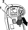
Close the tow bypass valve by rotating it back 90° (1/4 turn) before starting the engine. (Figure 91).
Note: Do not exceed 7 to 11 N∙m (5 to 8 ft-lb) torque to close the valve.
Pushing or Towing the Machine Forward Only
If you need to push or tow the machine forward only, you can just rotate the bypass valve.
Important: If you need to push or tow the machine in reverse, refer to Preparing the Machine to Push or Tow in Reverse.
-
Open the hood and remove the center shroud.
-
Open the tow bypass valve of the traction pump by rotating it 90° (1/4 turn) in either direction (Figure 90).
Note: Note the position of the valve when opening and closing it.
-
Push or tow the machine forward only.
Important: Do not push or tow the machine faster than 3 to 4.8 km/h (2 to 3 mph) or for more than 0.4 km (1/4 mile), because damage to the hydraulic system may occur. The bypass valve must be open whenever you push or tow the machine.
-
When the machine is ready for operation, close the tow bypass valve by rotating it back 90° (1/4 turn) before starting the engine.
Note: Do not exceed 7 to 11 N∙m (5 to 8 ft-lb) torque to close the valve.
Maintenance
Note: Determine the left and right sides of the machine from the normal operating position.
Note: Download a free copy of the electrical or hydraulic schematic by visiting www.Toro.com and searching for your machine from the Manuals link on the home page.
Important: Refer to your engine owner’s manual and cutting unit Operator's Manual for additional maintenance procedures.
Maintenance Safety
-
Before you leave the operator’s position, do the following:
-
Park the machine on a level surface.
-
Disengage and lower the cutting units.
-
Engage the parking brake.
-
Shut off the engine and remove the key.
-
Wait for all movement to stop.
-
Allow the machine to cool before adjusting, servicing, cleaning, or storing it.
-
-
Allow machine components to cool before performing maintenance.
-
If possible, do not perform maintenance while the engine is running. Keep away from moving parts.
-
Support the machine with jack stands whenever you work under the machine.
-
Carefully release pressure from components with stored energy.
-
Keep all parts of the machine in good working condition and all hardware tightened.
-
Replace all worn or damaged decals.
-
To ensure safe, optimal performance of the machine, use only genuine Toro replacement parts. Replacement parts made by other manufacturers could be dangerous, and such use could void the product warranty.
Recommended Maintenance Schedule(s)
| Maintenance Service Interval | Maintenance Procedure |
|---|---|
| After the first 8 hours |
|
| After the first 50 hours |
|
| After the first 200 hours |
|
| Before each use or daily |
|
| Every 50 hours |
|
| Every 100 hours |
|
| Every 200 hours |
|
| Every 400 hours |
|
| Every 500 hours |
|
| Every 800 hours |
|
| Every 1,000 hours |
|
| Every 2,000 hours |
|
| Every 6,000 hours |
|
| Before storage |
|
Pre-Maintenance Procedures
Preparing for Maintenance
-
Park the machine on a level surface, lower the cutting units, and engage the parking brake.
-
Shut off the engine, remove the key, and wait for all moving parts to stop.
Opening the Hood
-
Release the 2 hood latches (Figure 93).
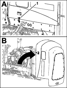
-
Rotate open the hood.
Closing the Hood
-
Carefully rotate the hood closed (Figure 94).
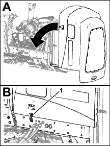
-
Secure the hood with the 2 hood latches.
Accessing the Battery Compartment
-
Release the rubber latch from the battery-compartment cover (Figure 93).
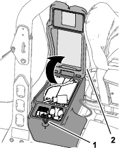
-
Rotate the cover up.
Tilting the Seat
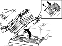
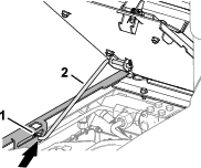
Lowering the Seat
-
Rotate the seat slightly, and lift the prop rod out of the dent of the seat support slot (Figure 98).
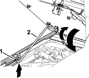
-
Carefully lower the seat until it latches securely.
Locating the Jacking Points
Note: Support the machine with jackstands whenever you work under the machine; refer to Specifications.
Use the following as machine-lift points:
-
Front of the machine—at the frame of the machine, forward of the wheel-drive motors (Figure 99).
Important: Do not support the machine at the wheel-drive motors. Keep the lifting equipment clear of hydraulic tubing and hoses.
-
Rear of the machine—at the center of the axle (Figure 100)
Note: Locate the jackstands of the specified capacity at both sides of the gear case and under the axle.
Important: Do not support the machine at the tie rod.
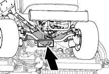
Lubrication
Greasing the Bearings and Bushings
| Maintenance Service Interval | Maintenance Procedure |
|---|---|
| Every 50 hours |
|
Grease Specification: No. 2 lithium grease
-
Prepare the machine for maintenance; refer to Preparing for Maintenance.
-
The grease fitting locations and quantities are as follows:
-
Brake shaft pivot bearings (5), refer to Figure 101
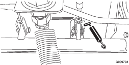
-
Rear axle pivot bushings (2), refer to Figure 102
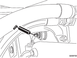
-
Steering cylinder ball joints (2), refer to Figure 103
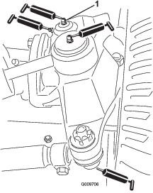
-
Tie rod ball joints (2), refer to Figure 103
-
King pin bushings (2), refer to Figure 103.
Note: The top fitting on the king pin should only be lubricated annually (2 pumps).
-
Lift arm bushings (1 per cutting unit), refer to Figure 104
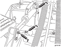
-
Lift cylinder bushings (2 per cutting unit), refer to Figure 104
-
Lift arm pivot bushings (1 per cutting unit), refer to Figure 105
-
Cutting unit carrier frame (2 per cutting unit), refer to Figure 105
-
Cutting unit lift arm pivot (1 per cutting unit), refer to Figure 105
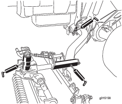
-
Engine Maintenance
Engine Safety
-
Shut off the engine before checking the oil or adding oil to the crankcase.
-
Do not change the governor speed or overspeed the engine.
Checking the Air Filter
| Maintenance Service Interval | Maintenance Procedure |
|---|---|
| Before each use or daily |
|
-
Prepare the machine for maintenance; refer to Preparing for Maintenance.
-
Open the hood; refer to Opening the Hood.
-
Check the service indicator at the end of the air filter housing (Figure 106).
Note: If a red band displays in the service indicator, change the air filter; refer to Removing the Filter.
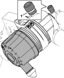
-
Squeeze the dust-ejector valve (Figure 107).
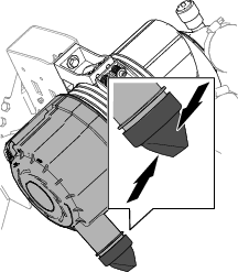
-
Close and latch the hood; refer to Closing the Hood.
Changing the Air Filter
| Maintenance Service Interval | Maintenance Procedure |
|---|---|
| Every 400 hours |
|
Removing the Filter
Service the air-cleaner filter only when the service indicator displays a red band. Changing the air filter before it is necessary only increases the chance of dirt entering the engine when the filter is removed.
Important: Be sure that the cover is seated correctly and seals with the air-cleaner body.
-
Prepare the machine for maintenance; refer to Preparing for Maintenance.
-
Open the hood; refer to Opening the Hood.
-
Check the air-cleaner body for wear of damage which could cause an air leak. Check the whole intake system for leaks, damage, or loose hose clamps.
Note: Replace a worn or damaged air cleaner and intake-system parts.
-
Pull the latch outward and rotate the air-cleaner cover counterclockwise (Figure 108).
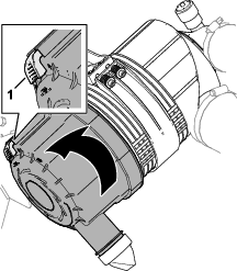
-
Remove the cover from the air-cleaner housing.
-
Before removing the filter, use low-pressure air—275 kPa (40 psi), clean and dry—to help remove large accumulations of debris packed between outside of primary filter and the housing. Avoid using high-pressure air, which could force dirt through the filter into the intake tract.
This cleaning process prevents debris from migrating into the intake when the primary filter is removed.
-
Remove the primary-filter element (Figure 109).
Note: Do not clean the air filter element.
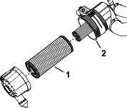
Installing the Filter
-
Check the safety-filter element (Figure 110). If it is dirty, replace it.
Important: Never attempt to clean the safety filter (Figure 110). Replace the safety filter with a new one after every 3 primary filter services.
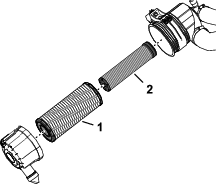
-
Inspect the new filter for shipping damage, checking the sealing end of the filter element and the body of the air filter.
Important: Do not use a damaged filter element.
-
Assemble the primary-filter element. Apply pressure to the outer rim of the element to seat it in the air-filter housing.
Important: Do not apply pressure to the flexible center of the filter.
-
Remove the dust-ejector valve from the air-cleaner cover, clean the cavity, and install the ejector valve to the cover.
-
Assemble the cover onto the air-cleaner housing, aligning the dust-ejector valve in a downward position—between approximately 5 o’clock to 7 o’clock when viewed from the end.
-
If a red band displays in the service indicator, press the reset button at the end of the indicator (Figure 111).

-
Close and latch the hood; refer to Closing the Hood.
Oil Specification
Use high-quality, low-ash engine oil that meets or exceeds the following specifications:
-
API service category CJ-4 or higher
-
ACEA service category E6
-
JASO service category DH-2
Important: Using engine oil other than API CJ-4 or higher, ACEA E6, or JASO DH-2 may cause the diesel particulate filter to plug or cause engine damage.
Use the following engine oil viscosity grade:
-
Preferred oil: SAE 15W-40: above -18°C (0°F)
-
Alternate oil: SAE 10W-30 or 5W-30 (all temperatures)
Toro Premium Engine Oil is available from your authorized Toro distributor in either 15W-40 or 10W-30 viscosity grades.
Checking the Engine-Oil Level
| Maintenance Service Interval | Maintenance Procedure |
|---|---|
| Before each use or daily |
|
The engine is shipped with oil in the crankcase; however, check the oil level before and after you first start the engine.
Note: The best time to check the engine oil is when the engine is cool before it has been started for the day. If the engine has already been run, wait 10 minutes before checking the oil level.
-
Prepare the machine for maintenance; refer to Preparing for Maintenance.
-
Unlatch and open the hood; refer to Opening the Hood.
-
Remove the dipstick from the dipstick tube (Figure 112) and wipe the dipstick with a clean rag.
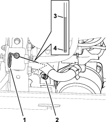
-
Fully insert the dipstick down into the dipstick tube, then pull the dipstick out and check the oil level.
Note: If the oil level is between the Full and Add oil-level marks, you do not need to add oil; skip to step 7.
-
If the oil level is low, remove the oil-fill cap (Figure 113) and gradually add small amounts of oil, checking the level frequently, until the level reaches the Full mark on the dipstick.
Important: Keep the engine-oil level between the upper and lower limits on the dipstick. Overfilling or underfilling the engine oil may cause severe engine damage.
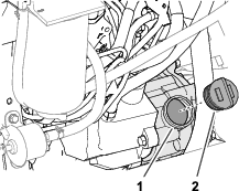
-
Install the oil-fill cap and dipstick.
-
Close and latch the hood; refer to Closing the Hood.
Crankcase Oil Capacity
5.7 L (6.0 US qt) with the filter.
Changing the Engine Oil and Filter
| Maintenance Service Interval | Maintenance Procedure |
|---|---|
| Every 500 hours |
|
Draining the Engine Oil
-
Prepare the machine for maintenance; refer to Preparing for Maintenance.
-
Remove the oil filler cap.
-
Align a drain pan under the drain plug.
-
Remove the drain plug (Figure 114) and let the oil drain into the pan.
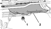
-
When oil stops draining from the engine, install the drain plug and torque it to 54 to 63 N∙m (40 to 47 ft-lb).
Changing the Oil Filter
-
Rotate the oil filter counterclockwise to remove it (Figure 115).
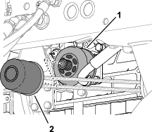
-
Wipe clean the filter adapter.
-
Apply a light coat of clean oil to the seal of the new filter.
Note: Do not overtighten the filter.
-
Thread the filter onto the filter adapter until the filter contacts the adapter, then tighten the filter 1 addition turn.
-
Add oil to the engine and install the filler cap; refer to Oil Specification, Crankcase Oil Capacity, and Checking the Engine-Oil Level.
Servicing the Diesel-Oxidation Catalyst (DOC) and the Soot Filter
| Maintenance Service Interval | Maintenance Procedure |
|---|---|
| Every 6,000 hours |
|
If engine faults , , or displays in the InfoCenter (Figure 116), clean the soot filter using the steps that follow:
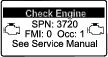
-
Refer to the Engine section in the Service Manual for information on disassembling and assembling the diesel-oxidation catalyst and the soot filter of the DPF.
-
Refer to your authorized Toro distributor for diesel-oxidation catalyst and the soot filter replacement parts or service.
-
Contact your authorized Toro distributor to reset the engine ECU after you install a clean DPF.
Fuel System Maintenance
Danger
Under certain conditions, fuel and fuel vapors are highly flammable and explosive. A fire or explosion from fuel can burn you and others and can cause property damage.
-
Fill the fuel tank outdoors, in an open area, when the engine is off and is cold. Wipe up any fuel that spills.
-
Do not fill the fuel tank completely full. Add fuel to the fuel tank until the level is 25 mm (1 inch) below the top of the tank, not the filler neck. This empty space in the tank allows the fuel to expand.
-
Never smoke when handling fuel, and stay away from an open flame or where fuel fumes may be ignited by a spark.
-
Store fuel in a clean, safety-approved container and keep the cap in place.
Draining the Fuel-Water Separator
| Maintenance Service Interval | Maintenance Procedure |
|---|---|
| Before each use or daily |
|
-
Prepare the machine for maintenance; refer to Preparing for Maintenance.
-
Open the hood; refer to Opening the Hood.
-
Place a drain pan under the fuel-water separator filter (Figure 117).
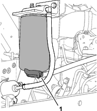
-
Loosen the drain valve at the bottom of the fuel-water separator filter, and allow the fuel and water to drain.
-
Close the drain valve at the bottom of the fuel-water separator filter.
-
Close and latch the hood; refer toClosing the Hood.
Checking the Fuel Lines and Connections
| Maintenance Service Interval | Maintenance Procedure |
|---|---|
| Every 400 hours |
|
Park the machine on a level surface, lower the cutting units, engage the parking brake, shut off the engine, and remove the key.
-
Prepare the machine for maintenance; refer to Preparing for Maintenance.
-
Open the hood; refer to Opening the Hood.
-
Inspect the fuel lines for wear, deterioration, damage, or loose fittings.
Note: Repair or replace any worn or damaged fuel lines; tighten any loose fittings.
-
Close and latch the hood; refer to Closing the Hood.
Changing the Fuel-Water Separator Filter
| Maintenance Service Interval | Maintenance Procedure |
|---|---|
| Every 400 hours |
|
-
Drain the fuel-water separator; refer to steps 1 through 4 in Draining the Fuel-Water Separator.
-
Clean the fuel-water separator filter and filter head (Figure 118).

-
Remove the separator filter from the filter head.
-
Clean the filter-mounting surface of the filter head.
-
Apply a coat of clean fuel to the gasket of the new separator filter.
-
Thread the separator filter into the filter head until the gasket contacts mounting surface, then rotate the filter an additional 1/2 turn.
-
Check that the drain valve at the bottom of the fuel-water separator filter is closed.
-
Start the engine and check for fuel leaks around the separator filter and filter head.
-
Shutoff the engine, remove the key, close and latch the hood; refer to Closing the Hood.
Changing the Engine-Fuel Filter
| Maintenance Service Interval | Maintenance Procedure |
|---|---|
| Every 400 hours |
|
-
Prepare the machine for maintenance; refer to Preparing for Maintenance.
-
Open the hood; refer to Opening the Hood.
-
Clean the area around the fuel-filter head (Figure 119).
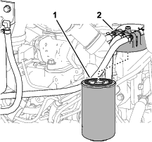
-
Remove the filter and clean the filter-head mounting surface (Figure 119).
-
Lubricate the filter gasket with clean lubricating engine oil. Refer to the engine owner’s manual, included with the machine, for additional information.
-
Install the dry filter canister, by hand, until the gasket contacts the filter head, then rotate it an additional 1/2 turn.
-
Start the engine and check for fuel leaks around the filter head.
-
Shutoff the engine, remove the key, close and latch the hood; refer to Closing the Hood.
Draining and Cleaning the Fuel Tank
| Maintenance Service Interval | Maintenance Procedure |
|---|---|
| Every 800 hours |
|
| Before storage |
|
Drain and clean the fuel tank if the fuel system becomes contaminated or if the machine is to be stored for an extended period. Use clean fuel to flush out the tank.
-
Prepare the machine for maintenance; refer to Preparing for Maintenance.
-
Align a drain container under the drain valve at the bottom of the fuel tank (Figure 120).
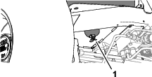
-
Open the drain valve and allow the fuel to drain.
-
If needed, add clean fuel to the fuel tank to flush it out.
-
Close the drain valve.
Note: When you add fuel to the tank, check the drain valve for leaks.
Cleaning the Fuel-Intake Screen
Park the machine on a level surface, lower the cutting units, engage the parking brake, shut off the engine, and remove the key.
The fuel-intake tube, located inside the fuel tank, is equipped with a screen to help prevent debris from entering the fuel system. Remove the fuel-intake tube and clean the screen as required.
-
Prepare the machine for maintenance; refer to Preparing for Maintenance.
-
Tilt the seat; refer to Tilting the Seat.
-
Remove the clamp that secures the hose to the fuel pick-up tube (Figure 121).
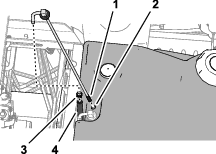
-
Remove the fuel pick-up tube and rubber bushing from the tank.
-
Clean the screen at the end of the fuel pick-up tube (Figure 121).
-
Insert the fuel pick-up tube and rubber bushing into the tank until the bushing is seated into the tank.
-
Assemble the hose onto the fuel pick-up tube and secure it with the clamp.
-
Lower and latch the seat; refer to Lowering the Seat.
Electrical System Maintenance
Electrical System Safety
-
Disconnect the battery before repairing the machine. Disconnect the negative terminal first and the positive last. Connect the positive terminal first and the negative last.
-
Charge the battery in an open, well-ventilated area, away from sparks and flames. Unplug the charger before connecting or disconnecting the battery. Wear protective clothing and use insulated tools.
Disconnecting the Battery
Danger
Battery electrolyte contains sulfuric acid, which is fatal if consumed and causes severe burns.
-
Do not drink electrolyte and avoid contact with skin, eyes, or clothing. Wear safety glasses to shield your eyes and rubber gloves to protect your hands.
-
Fill the battery where clean water is always available for flushing the skin.
-
Prepare the machine for maintenance; refer to Preparing for Maintenance.
-
Open the battery-compartment cover; refer to Accessing the Battery Compartment.
-
Disconnect the negative battery cable (Figure 122).
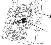
-
Slide the rubber boot off the positive battery-cable clamp, and disconnect the positive battery cable.
Connecting the Battery
-
Install the positive battery cable (red) to the positive (+) battery post (Figure 123).
-
Install the negative battery cable (black) to the negative (-) battery post.
-
Apply a coat of Grafo 112X (skin-over) grease, Toro Part No. 505-47 to the battery posts and battery-cable clamps.
-
Slide the rubber boot over the positive battery-cable clamp.
-
Close and latch the battery-compartment cover.
Charging the Battery
-
Disconnect the battery; refer to Disconnecting the Battery.
-
Connect a 3 to 4 A battery charger to the battery posts.
-
Charge the battery at a rate of 3 to 4 A for 4 to 8 hours.
-
When the battery is charged, disconnect the charger from the electrical outlet and battery posts.
-
Connect the battery; refer to Connecting the Battery.
Servicing the Battery
| Maintenance Service Interval | Maintenance Procedure |
|---|---|
| Every 50 hours |
|
Note: Keep the terminals and the entire battery case clean because a dirty battery will discharge slowly.
-
Prepare the machine for maintenance; refer to Preparing for Maintenance.
-
Open the battery-compartment cover; refer to Accessing the Battery Compartment.
-
Check the condition of the battery.
Note: Replace a worn or damaged battery.
-
Disconnect the battery cables, and remove the battery from the machine; refer to Disconnecting the Battery.
-
Wash the entire battery case with a solution of sodium bicarbonate (baking soda) and water.
-
Rinse the case with clean water.
-
Assemble the battery to the machine and connect the battery cables; refer to Connecting the Battery.
-
Close and latch the battery-compartment cover.
Replacing a Fuse
The fuse block is in the battery compartment.
-
Prepare the machine for maintenance; refer to Preparing for Maintenance.
-
Open the battery-compartment cover; refer to Accessing the Battery Compartment.
-
Replace the open fuse (Figure 124) with the same fuse type and amperage rating.
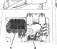
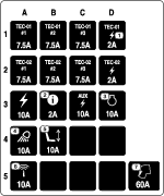
-
Close and latch the battery-compartment cover.
Drive System Maintenance
Checking the Tire Air Pressure
| Maintenance Service Interval | Maintenance Procedure |
|---|---|
| Before each use or daily |
|
Important: Maintain the recommended pressure in all tires to ensure a good quality of cut and proper machine performance. Do not underinflate the tires.
-
Prepare the machine for maintenance; refer to Preparing for Maintenance.
-
Measure the tire air pressure.
Note: The correct air pressure in the tires is 83 to 103 kPa (12 to 15 psi).
-
If needed add air to or remove air from the tire.
-
Repeat steps 2 and 3 at the other tires.
Checking the Torque of the Wheel Nuts
| Maintenance Service Interval | Maintenance Procedure |
|---|---|
| After the first 8 hours |
|
| Every 200 hours |
|
Warning
Failure to maintain proper torque of the wheel nuts could result in failure or loss of a wheel and may result in personal injury.
Torque the front and rear wheel nuts to 115 to 136 N∙m (85 to 100 ft-lb) after 1 to 4 hours of operation and again after 8 hours of operation. Torque the wheel nuts every 200 hours thereafter.
-
Prepare the machine for maintenance; refer to Preparing for Maintenance.
-
Torque the wheel nuts to 115 to 136 N∙m (85 to 100 ft-lb).
Note: The front wheel nuts are 1/2–20 UNF; the rear wheel nuts are M12 x 1.6-6H (metric).
Checking for End-Play in the Planetary Drives
| Maintenance Service Interval | Maintenance Procedure |
|---|---|
| Every 400 hours |
|
Danger
A machine on a jack may be unstable and slip off the jack, injuring anyone beneath it.
-
Do not start the engine while the machine is on a jack.
-
Always remove the key from the switch before getting off the machine.
-
Block the tires when you are raising the machine with a jack.
-
Support the machine with jack stands.
There should be no end-play in the planetary drives/drive wheels (i.e., the wheels should not move when you pull or push them in a direction parallel to the axle).
-
Prepare the machine for maintenance; refer to Preparing for Maintenance.
-
Chock the rear wheels and raise the front of machine; refer to Specifications and Locating the Jacking Points.
-
Support the front frame of the machine with jack stands.
-
Grasp 1 of the front drive wheels and push/pull it toward and away from the machine, noting any movement.
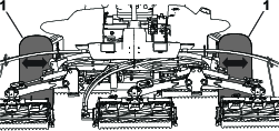
-
Repeat step 4 for the other drive wheel.
-
If either wheel moves, contact your authorized Toro distributor to have the planetary drive rebuilt.
Checking the Planetary Gear-Drive Lubricant
| Maintenance Service Interval | Maintenance Procedure |
|---|---|
| Every 400 hours |
|
Lubricant Specification: high quality SAE 85W-140 gear oil
-
Park the machine on level surface, position the wheel so that the fill plug is at the 12 o'clock position, the check plug is at 3 o'clock position, and the drain plug is at the 6 o'clock position (Figure 126).
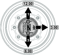
-
Remove the check plug at the 3 o’clock position (Figure 126).
The oil level should be at the bottom of the check-plug hole.
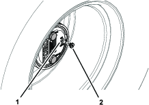
-
If the oil level is low, remove the fill plug at the 12 o’clock position and add oil until it begins to flow out of the hole at the 3 o’clock position.
-
Check the O-ring for the plug(s) for wear or damage.
Note: Replace the O-ring(s) as needed.
-
Install the plug(s).
-
Repeat steps 1 through 5 on the planetary gear assembly at the other side of the machine.
Changing the Planetary-Gear-Drive Oil
| Maintenance Service Interval | Maintenance Procedure |
|---|---|
| After the first 50 hours |
|
| Every 800 hours |
|
Lubricant specification: high quality SAE 85W-140 gear oil
Planetary and brake housing lubrication capacity: 0.65 L (22 fl oz)
Draining the Planetary-Gear-Drive
-
Park the machine on level surface, position the wheel so that the fill plug is at the 12 o'clock position, the check plug is at 3 o'clock position, and the drain plug is at the 6 o'clock position; refer to Figure 126 in Checking the Planetary Gear-Drive Lubricant.
-
Remove the fill plug at the 12 o’clock position and the check plug at the 3 o’clock position (Figure 128).
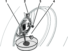
-
Place a drain pan under the planetary hub, remove the drain plug at the 6 o’clock position, and allow the oil to fully drain (Figure 128).
-
Check the O-rings for the fill, check, and drain plugs for wear or damage.
Note: Replace the O-ring(s) as needed.
-
Install the drain plug into the drain hole of the planetary housing (Figure 128).
-
Place a drain pan under the brake housing, remove the drain plug, and allow the oil to fully drain (Figure 129).
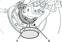
-
Check the O-ring for the plug for wear or damage and install the drain plug into the brake housing.
Note: Replace the O-ring as needed.
Filling the Planetary-Gear-Drive with Lubricant
-
Through the fill-plug hole, slowly fill the planetary with 0.65 L (22 fl oz) of high quality SAE 85W-140 gear oil.
Important: If the planetary fills before you add 0.65 L (22 fl oz) of oil, wait 1 hour or install the plug and move the machine approximately 3 m (10 ft) to distribute the oil through the brake system. Then, remove the plug and add the remaining oil.
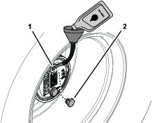
-
Install the fill plug and the check plug.
-
Wipe clean the planetary and brake housings (Figure 131).
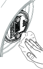
-
Repeat steps 1 through 7 in Draining the Planetary-Gear-Drive and steps 1 through 3 in this procedure for the planetary/brake assembly at the other side of the machine.
Checking the Oil Level of the Rear Axle
| Maintenance Service Interval | Maintenance Procedure |
|---|---|
| Before each use or daily |
|
| Every 400 hours |
|
Axle Oil Specification: SAE 85W-140 gear oil
-
Prepare the machine for maintenance; refer to Preparing for Maintenance
-
Remove a check plug from 1 end of the axle housing (Figure 132).
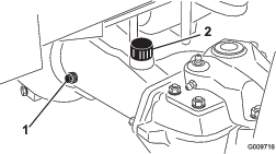
-
Check the gear oil level in the axle through the check-plug hole.
Note: The gear-oil level is correct if the oil level is at the bottom of the check-plug hole.
-
If the gear-oil level low, remove the fill plug and add the specified gear oil to raise the oil level to the bottom of the check-plug hole.
-
Install the check plug.
-
If removed, install the fill plug.
Changing the Oil in the Rear Axle
| Maintenance Service Interval | Maintenance Procedure |
|---|---|
| After the first 200 hours |
|
| Every 800 hours |
|
Rear Axle Oil Capacity: 2.4 L (80 fl oz)
-
Prepare the machine for maintenance; refer to Preparing for Maintenance.
-
Clean the area around the 3 drain plugs (Figure 133)—1 at each bevel-gear case (outboard of the axle housings) and 1 in the center-gear case.
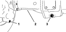
-
Remove each drain plug (Figure 133) and allow the oil to drain into a drain pan.
-
Remove the 2 axle housing check plugs and the fill plug to ease in draining of the oil (Figure 134).
-
Install the 3 drain plugs and the check plug at the axle housing with the breather fitting.
-
At the fill plug axle port, fill the axle with approximately 2.37 L (80 fl oz) of 85W-140 gear oil or until the oil level is at the bottom of the hole.
-
Install the check plug and the fill plug.
Checking the Lubricant in the Reduction-Gear Case
| Maintenance Service Interval | Maintenance Procedure |
|---|---|
| Before each use or daily |
|
| Every 400 hours |
|
Reduction-Gear Case Oil Specification: SAE 85W-140 gear oil
-
Prepare the machine for maintenance; refer to Preparing for Maintenance.
-
Remove the check/fill plug from the left side of the reduction-gear case (Figure 135).
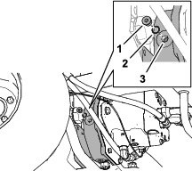
-
Check the O-ring for the plug is not worn or damaged.
-
Check the gear-case oil level.
Note: The gear-oil level is correct if the oil level is at the bottom of the check/fill-plug hole.
-
If the gear-oil level is low, add enough of the specified case oil to bring the level up to the bottom of the check/fill-plug hole.
-
Install the check/fill plug.
Mow Speed-Spacer Table
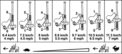
Adjusting Maximum Mow-Ground Speed
Adjusting the Mow Speed-Spacers
-
Prepare the machine for maintenance; refer to Preparing for Maintenance.
-
Use the Mow Speed-Spacer Table to determine the maximum ground speed when you mow, and the position of the short spacers that limit mow-ground speed; refer to Mow Speed-Spacer Table.
Note: Each short spacer adjusts the mowing speed by 0.8 km/h (0.5 mph).
-
Below the traction pedal, remove the stop bolt and flange locknut that secure the spacers to the mow-stop block (Figure 137).
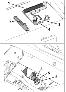
-
Position the long spacer above the mow-stop block.
-
Position the short spacers as you determined in step 2.
-
Secure the spacers to the mow-stop block with the stop bolt and flange locknut that you removed in step 3.
Note: You must install all 6 short spacers and the long spacer.
-
Set the mow speed in the InfoCenter; refer to Setting the Mow Speed in the InfoCenter.
Setting the Mow Speed in the InfoCenter
The mow speed setting in the InfoCenter is used by the TEC to adjust reel speed of the cutting units to the maximum mow-ground speed.
-
In the InfoCenter, access the MAIN MENU.
-
In the MAIN MENU, press the middle button until the SETTING option is highlighted, and press the right button.
-
In the SETTING MENU, press the middle button until the PROTECTED MENUS option is highlighted, and press the right button.
-
In the PROTECTED MENUS screen, enter the PIN code; refer to Protected Menus.
-
In the SETTINGS menu, press the middle button until the MOW SPEED option is highlighted, and press the right button.
-
In the MOW SPEED screen, press the middle button or the right button until the mow speed displayed in the InfoCenter is the same as the Maximum Mow-Ground Speed that you determined in step 2 of Adjusting the Mow Speed-Spacers.
Note: The mow speed setting increases or decreases in 0.8 kph (0.5 mph) increments.
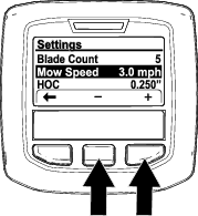
Note: The indicator light illuminates and Advisory #176 (Reel Speed Changed) displays.

-
Press the left button to exit the Settings menu.
Adjusting the Traction Drive for Neutral
The machine must not creep when you release the traction pedal. If it does creep, an adjustment adjust the traction drive for neutral.
-
Park the machine on a level surface, shut off the engine, position the speed control into the low range, and lower the cutting units.
-
Press only the right brake pedal and engage the parking brake.
-
Jack up the left side of the machine until the left front tire is off the shop floor. Support the machine with jack stands to prevent it from falling accidentally; refer to Specifications and Locating the Jacking Points.
-
Start the engine and allow it run at low idle.
-
Adjust the jam nuts on the rod end to move the traction rod forward to eliminate forward creep or rearward to eliminate rearward creep (Figure 140 and Figure 141).
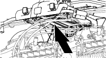
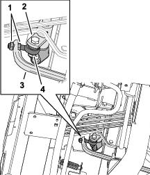
-
When the wheel stops rotating, tighten the jam nuts to secure the adjustment.
-
Shut off the engine and remove the key.
-
Remove the jack stands and lower the machine to the shop floor.
-
Test drive the machine to ensure that it does not creep.
Checking the Rear-Wheel Alignment
| Maintenance Service Interval | Maintenance Procedure |
|---|---|
| Every 800 hours |
|
-
Prepare the machine for maintenance; refer to Preparing for Maintenance.
-
Measure the center-to-center distance (at axle height) at the front and rear of the steering tires.
Note: The front measurement must be 3 mm (1/8 inch) less than the rear measurement (Figure 142).
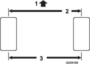
Adjusting the Rear-Wheel Toe-In
-
At the rear axle, remove the cotter pin and the slotted nut from either tie-rod end (Figure 143).
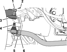
-
Separate the tie-rod end from the axle case-steering arm.
-
Loosen the clamps at both ends of the tie rods (Figure 143).
-
Rotate the detached ball joint inward or outward 1 complete revolution.
-
Tighten the clamp at the detached end of the tie rod.
-
Rotate the entire tie-rod assembly the same direction (inward or outward) 1 complete revolution.
-
Tighten the clamp at the connected end of the tie rod.
-
Assemble the tie-rod end to the axle case-steering arm with the slotted nut.
-
Measure the toe-in; refer to Checking the Rear-Wheel Alignment.
-
If needed, remove the slotted nut and repeat steps 2 through 9.
-
When the difference between the front and rear measurements are 3 mm (1/8 inch) less, tighten the slotted nut and install a new cotter pin.
Cooling System Maintenance
Cooling System Safety
-
Swallowing engine coolant can cause poisoning; keep out of reach from children and pets.
-
Discharge of hot, pressurized coolant or touching a hot radiator and surrounding parts can cause severe burns.
-
Always allow the engine to cool at least 15 minutes before removing the radiator cap.
-
Use a rag when opening the radiator cap, and open the cap slowly to allow steam to escape.
-
Coolant Specification
The coolant reservoir is filled at the factory with a 50/50 solution of water and ethylene glycol base extended-life coolant. Check the coolant level before you first start the engine and daily thereafter; refer to Checking the Coolant Level.
The following commercially available coolants or a manufacturer-specified equivalent meeting the long-life coolant specification:
|
Ford (Motorcraft™) |
WSS-M97B44-D |
|
FCA—Chrysler (Mopar™) |
MS-12106 |
|
General Motors (AC Delco™) |
GM6277M (Dex-Cool™) |
|
GMW 3420 |
|
|
Volkswagen |
G12 |
|
G12+ |
|
|
G12++ |
|
|
Coolants meeting technical standards ASTM D3306 or D4985, or SAE J1034, J814, or 1941. |
|
|
Important: Do not rely on the color of the coolant to identify the difference between conventional (IAT) and extended-life (OAT) coolant types.Coolant manufacturers may dye extended-life coolant (OAT) in one of the following colors: red, pink, orange, yellow, blue, teal, violet, and green. |
|
|
Ethylene-Glycol Coolant Type |
Corrosion Inhibitor Type |
Service Interval |
|
Extended-life antifreeze |
Organic-acid technology (OAT) |
5-years |
|
Conventional antifreeze (green) |
Inorganic-acid technology (IAT) |
2-years |
Note: When adding coolant to the machine, you will not damage the cooling system by mixing conventional (IAT) antifreeze with extended-life (OAT) antifreeze. However, mixing antifreeze types degrades the long life/extended life attribute of the OAT formulation.
Important: The service interval of conventional (IAT) and extended-life (OAT) blended-coolant mixture—at any ratio—lasts as long as the coolant with the shortest service interval: 2 years.
Checking the Coolant Level
| Maintenance Service Interval | Maintenance Procedure |
|---|---|
| Before each use or daily |
|
Caution
If the engine has been running, the pressurized, hot coolant can escape and cause burns.
-
Do not open the radiator cap when the engine is running.
-
Use a rag when opening the radiator cap, and open the cap slowly to allow steam to escape.
-
Prepare the machine for maintenance; refer to Checking the Coolant Level.
-
Open the hood, and wait for the engine to cool; refer to Opening the Hood.
-
Carefully remove the radiator cap (Figure 144).
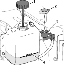
-
Check the coolant level in the radiator.
Note: The coolant level is correct if it is to the top of the filler neck of the radiator (Figure 144).
-
Check the coolant level in the expansion tank.
Note: The coolant level is correct if it is to the FULL mark of the expansion tank.
-
If the coolant is low, add the specified coolant to the radiator, expansion tank, or both; refer to Coolant Specification.
-
Install the radiator cap and the expansion-tank cap.
-
Close and latch the hood; refer to Closing the Hood.
Servicing the Engine Cooling System
| Maintenance Service Interval | Maintenance Procedure |
|---|---|
| Before each use or daily |
|
-
Prepare the machine for maintenance; refer to Preparing for Maintenance.
-
Unlatch and open the rear screen (Figure 145).
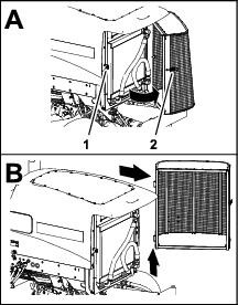
-
Clean both sides of the screen.
-
Lift the screen off the hinge pins, and remove the screen from the machine.
-
Open the hood; refer to Opening the Hood.
-
Clean both sides of the oil cooler/radiator area (Figure 146) thoroughly with compressed air. Start from the front and blow the debris out toward the back. Then clean from the back side and blow toward the front. Repeat the procedure several times until all chaff and debris is removed.
Important: Cleaning the oil cooler/radiator with water may promote premature corrosion damage to components and compact debris.
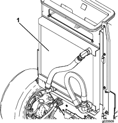
-
Close and latch the hood, Closing the Hood.
-
Assemble the screen onto the hinge pins (Figure 147).
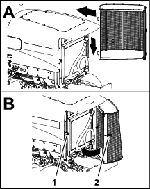
-
Close and latch the screen.
Brake Maintenance
Adjusting the Service Brakes
Adjust the service brakes when there is more than 13 mm (1/2 inch) of free travel of the brake pedal, or if the brakes slip. Free travel is the distance the brake pedal moves before you feel braking-pedal resistance.
-
Prepare the machine for maintenance; refer to Preparing for Maintenance.
-
Disengage the pedal-locking latch between the brake pedals (Figure 148) so that both pedals work independently of each other.
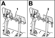
-
Loosen the front jam nut on the threaded end of the brake cable (Figure 149).
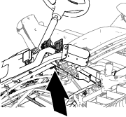
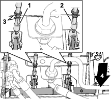
-
To reduce free travel of the brake pedals, tighten the rear jam nut to move the cable rearward until the brake pedals have 0 to 13 mm (0 to 1/2 inch) of free travel.
Note: Ensure that there is no brake-cable tension when the pedal is released.
-
Tighten the front jam nut after the brakes are adjusted correctly.
-
If needed, repeat steps 3 through 5 at the other brake cable.
Belt Maintenance
Servicing the Alternator Belt
| Maintenance Service Interval | Maintenance Procedure |
|---|---|
| Every 100 hours |
|
Check the condition and tension of the belts (Figure 150) after every 100 operating hours.
-
Park the machine on a level surface, lower the cutting units, engage the parking brake, shut off the engine, and remove the key.
-
Open the hood; refer to Opening the Hood.
-
Check the condition of the alternator belt.
Note: Replace a worn or damaged belt.
-
Check the belt tension.
Note: Belt tension is correct when the belt deflects 10 mm (3/8 inch) when a force of 45 N (10 lb) is applied on the belt midway between the pulleys.
-
If belt deflection is more than or less than 10 mm (3/8 inch), loosen the alternator mounting bolts (Figure 150).
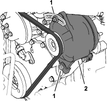
-
Increase or decrease the alternator-belt tension, and tighten the mounting bolts.
-
Check the deflection of the belt again to ensure that the tension is correct.
-
Close and latch the hood; refer to Closing the Hood.
Hydraulic System Maintenance
Hydraulic System Safety
-
Seek immediate medical attention if fluid is injected into skin. Injected fluid must be surgically removed within a few hours by a doctor.
-
Ensure that all hydraulic-fluid hoses and lines are in good condition and all hydraulic connections and fittings are tight before applying pressure to the hydraulic system.
-
Keep your body and hands away from pinhole leaks or nozzles that eject high-pressure hydraulic fluid.
-
Use cardboard or paper to find hydraulic leaks.
-
Safely relieve all pressure in the hydraulic system before performing any work on the hydraulic system.
Checking the Hydraulic Lines and Hoses
| Maintenance Service Interval | Maintenance Procedure |
|---|---|
| Before each use or daily |
|
Check the hydraulic lines and hoses for leaks, kinked lines, loose mounting supports, wear, loose fittings, weather deterioration, and chemical deterioration. Make all necessary repairs before operating.
Hydraulic Fluid Specifications
The reservoir is filled at the factory with high-quality hydraulic fluid. Check the level of the hydraulic fluid before you first start the engine and daily thereafter; refer to Checking the Hydraulic-Fluid Level.
Recommended hydraulic fluid: Toro PX Extended Life Hydraulic Fluid; available in 19 L (5 US gallon) pails or 208 L (55 US gallon) drums.
Note: A machine using the recommended replacement fluid requires less frequent fluid and filter changes.
Alternative hydraulic fluids: If Toro PX Extended Life Hydraulic Fluid is not available, you may use another conventional, petroleum-based hydraulic fluid having specifications that fall within the listed range for all the following material properties and that it meets industry standards. Do not use synthetic fluid. Consult with your lubricant distributor to identify a satisfactory product.
Note: Toro does not assume responsibility for damage caused by improper substitutions, so use products only from reputable manufacturers who will stand behind their recommendation.
| Material Properties: | ||
| Viscosity, ASTM D445 | cSt @ 40°C (104°F) 44 to 48 | |
| Viscosity Index ASTM D2270 | 140 or higher | |
| Pour Point, ASTM D97 | -37°C to -45°C (-34°F to -49°F) | |
| Industry Specifications: | Eaton Vickers 694 (I-286-S, M-2950-S/35VQ25 or M-2952-S) | |
Note: Many hydraulic fluids are almost colorless, making it difficult to spot leaks. A red dye additive for the hydraulic fluid is available in 20 ml (0.67 fl oz) bottles. A bottle is sufficient for 15 to 22 L (4 to 6 US gallons) of hydraulic fluid. Order Part No. 44-2500 from your authorized Toro distributor.
Important: Toro Premium Synthetic Biodegradable Hydraulic Fluid is the only synthetic biodegradable fluid approved by Toro. This fluid is compatible with the elastomers used in Toro hydraulic systems and is suitable for a wide-range of temperature conditions. This fluid is compatible with conventional mineral oils, but for maximum biodegradability and performance, the hydraulic system should be thoroughly flushed of conventional fluid. The oil is available in 19 L (5 US gallons) pails or 208 L (55 US gallons) from your authorized Toro distributor.
Checking the Hydraulic-Fluid Level
| Maintenance Service Interval | Maintenance Procedure |
|---|---|
| Before each use or daily |
|
The reservoir is filled at the factory with high-quality hydraulic fluid.
-
Prepare the machine for maintenance; refer to Preparing for Maintenance.
-
Clean the area around the filler neck and cap of the hydraulic tank (Figure 151).
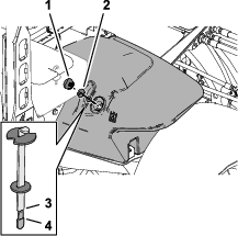
-
Remove the hydraulic-tank cap from the tank.
-
Remove the dipstick from the filler neck and wipe it with a clean rag.
-
Insert the dipstick into the filler neck; then remove it and check the fluid level.
The correct hydraulic-fluid level is between the Full mark and the Add mark on the dipstick.
-
If the level is low, add the specified hydraulic fluid to raise the fluid level to the Full mark.
-
Install the dipstick and hydraulic-tank cap to the tank.
Replacing the Hydraulic Filters
| Maintenance Service Interval | Maintenance Procedure |
|---|---|
| Every 800 hours |
|
| Every 1,000 hours |
|
|
Name |
Toro Part No. |
Location |
|
Return filter |
94-2621 |
Below the right frame channel. |
|
Charge filter |
75-1310 |
Under the seat plate. |
|
Important: Using another type of filter may void the warranty on some components. |
||
Replacing the Charge Filter
-
Prepare the machine for maintenance; refer to Preparing for Maintenance.
-
Tilt the seat; refer to Tilting the Seat.
-
Clean the area around the charge filter and filter head (Figure 152).
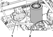
-
Align a drain pan under the filter, and remove the filter.
-
Wipe the filter mounting filter surface of the filter head with a clean rag.
-
Lubricate the new filter gasket and fill the filter with the specified hydraulic fluid; refer to Hydraulic Fluid Specifications.
-
Thread the filter onto the filter head until the gasket contacts the mounting plate, then tighten the filter an additional 1/2 turn.
Replacing the Return Filter
-
Clean the area around the return filter and filter head (Figure 153).
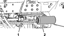
-
Align a drain pan under the return filter, and remove the filter.
-
Wipe the filter mounting filter surface of the filter head with a clean rag.
-
Lubricate the new filter gasket, fill the filter with the specified hydraulic fluid, and then drain the filter; refer to Hydraulic Fluid Specifications.
-
Thread the filter onto the filter head until the gasket contacts the mounting plate, then tighten the filter an additional 1/2 turn.
Purging Air from the Hydraulic System
-
Start the engine and let it run for about 2 minutes to purge air from the system.
-
Check around the filters and filter heads for hydraulic leaks.
Note: Repair any hydraulic leaks.
-
Shut off the engine and remove the key.
-
Lower the seat; refer to Lowering the Seat.
Hydraulic Fluid Capacity
28.4 L (7.5 US gallons); refer to Hydraulic Fluid Specifications
Changing the Hydraulic Fluid
| Maintenance Service Interval | Maintenance Procedure |
|---|---|
| Every 800 hours |
|
| Every 2,000 hours |
|
Draining the Hydraulic Fluid
If the fluid becomes contaminated, contact your local authorized Toro distributor, because the system must be flushed. Contaminated fluid looks milky or black when compared to clean fluid.
Drain Pan Capacity: 30L (8 US gallons) or more
-
Prepare the machine for maintenance; refer to Preparing for Maintenance.
-
Open the hood; refer to Opening the Hood.
-
Align the drain pan under the hydraulic tank (Figure 154).
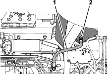
-
Disconnect the case-return hose from the straight fitting at the bottom of the tank, and drain hydraulic fluid.
-
When the hydraulic fluid stops draining, assemble the case-return hose to the tank fitting.
-
Torque the hose fitting to 50 to 63 N∙m (37 to 47 ft-lb).
Filling the Hydraulic Tank
-
Fill the reservoir with the specified hydraulic fluid; refer to Hydraulic Fluid Specifications and Hydraulic Fluid Capacity.
Important: Use only the hydraulic fluids specified. Other fluids could cause system damage.
-
Install the dipstick and hydraulic-tank cap to the tank.
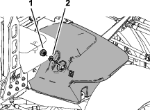
-
Start the engine and operate all the hydraulic controls to distribute hydraulic fluid throughout the system.
-
Check for hydraulic leaks, shut off the engine, and remove the key.
Repair all hydraulic leaks.
-
Close and latch the hood; refer to Closing the Hood.
-
Check the fluid level; refer to Checking the Hydraulic-Fluid Level.
Note: If needed, add enough to raise the level to the Full mark on the dipstick. Do not overfill the hydraulic tank.
Cutting Unit Maintenance
Blade Safety
A worn or damaged blade or bedknife can break, and a piece could be thrown toward you or bystanders, resulting in serious personal injury or death.
-
Inspect the blades and bedknives periodically for excessive wear or damage.
-
Use care when checking the blades. Wear gloves and use caution when servicing them. Only replace or backlap the blades and bedknives; never straighten or weld them.
-
On machines with multiple cutting units, take care when rotating a cutting unit; it can cause the reels in the other cutting units to rotate.
Backlapping the Cutting Units
Warning
Contact with the reels or other moving parts can result in personal injury.
-
Keep your fingers, hands, and clothing away from the reels or other moving parts.
-
Never attempt to turn the reels by hand or foot while the engine is running.
Note: Additional instructions and procedures on backlapping are available in the Toro Sharpening Reel and Rotary Mowers Manual, Form No. 80-300SL.
Preparing the Machine
-
Park the machine on a level surface, lower the cutting units, engage the parking brake, shut off the engine, and move the PTO switch to the DISENGAGE position.
-
Open the hood; refer to Opening the Hood.
-
Make initial reel-to-bedknife adjustments appropriate for backlapping on all cutting units which are to be backlapped; refer to the cutting unit Operator's Manual.
-
Rotate the front, rear, or both backlap levers to the R (backlap) position (Figure 156).
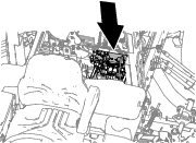
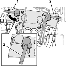
Lapping the Reels and Bedknife
Danger
Changing the engine speed while backlapping may cause the reels to stall.
-
Never change the engine speed while backlapping.
-
Backlap only at low idle engine speed.
Note: When backlapping, the front units all operate together, and the rear units operate together.
-
Ensure that the traction pedal is in the Neutral position and the parking brake is engaged.
-
Start the engine and run it at low-idle speed.
-
Rotate the lever for the mow-speed limiter forward to the MOW position (Figure 158).
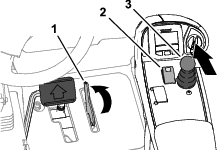
-
Press the PTO switch to the ENGAGE position.
-
Move the lower mow/raise control lever forward.
Note: The reels you set for backlapping run backward.
-
Apply lapping compound to the reels with a long-handled brush.
Danger
Contacting the cutting units when they are moving could cause personal injury.
-
Do not use a short-handled brush.
-
To avoid personal injury, be certain that you are clear of the cutting units before proceeding.
-
-
If the reels stall or become erratic while backlapping, increase the throttle speed until the reel stabilizes.
-
If you need to make an adjustment to the cutting units while backlapping, perform the following steps:
-
Move the lower mow/raise control lever rearward.
Note: The cutting units shut off, but do not raise.
-
Press the PTO switch to the DISENGAGE position.
-
Shut off the engine and remove the key.
-
Adjust the cutting units.
-
Repeat steps 2 through 7.
-
-
Repeat step 6 for all cutting units that you want to backlap.
Finishing Backlapping
Important: If you do not return the backlap switch to the OFF position after backlapping, the cutting units will not raise or function properly.
-
Shut off the engine and remove the key.
-
Wash all lapping compound off from the cutting units.
-
Adjust the cutting unit reel-to-bedknife as needed.
-
Rotate the backlap levers to the F (mow) position.
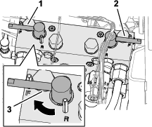
-
For a better cutting edge, run a file across the front face of the bedknife after lapping.
Note: This removes any burrs or rough edges that may have built up on the cutting edge.
-
Close and latch the hood; refer to Closing the Hood.
Cleaning
Washing the Machine
Wash the machine as needed using water alone or with a mild detergent. You may use a rag when washing the machine.
Important: Do not use brackish or reclaimed water to clean the machine.
Important: Do not use power-washing equipment to wash the machine. Power-washing equipment may damage the electrical system, loosen important decals, or wash away necessary grease at friction points. Avoid excessive use of water near the control panel, engine, and battery.
Important: Do not wash the machine with the engine running. Washing the machine with the engine running may result in internal engine damage.
Storage
Storage Safety
-
Before you leave the operator’s position, do the following:
-
Park the machine on a level surface.
-
Disengage and lower the cutting units.
-
Engage the parking brake.
-
Shut off the engine and remove the key.
-
Wait for all movement to stop.
-
Allow the machine to cool before adjusting, servicing, cleaning, or storing it.
-
-
Do not store the machine or fuel container where there is an open flame, spark, or pilot light, such as on a water heater or other appliance.
Preparing the Traction Unit
-
Park the machine on a level surface, lower the cutting units, engage the parking brake, shut off the engine, and remove the key.
-
Thoroughly clean the traction unit, cutting units, and the engine.
-
Check the tire pressure; refer to Checking the Tire Air Pressure.
-
Check all fasteners for looseness; tighten them as necessary.
-
Grease or oil all grease fittings and pivot points. Wipe up any excess lubricant.
-
Lightly sand and use touch-up paint on painted areas that are scratched, chipped, or rusted. Repair any dents in the metal body.
-
Service the battery and cables as follows; refer to Electrical System Safety:
-
Remove the battery terminals from the battery posts.
-
Clean the battery, terminals, and posts with a wire brush and baking-soda solution.
-
Coat the cable terminals and battery posts with Grafo 112X skin-over grease (Toro Part No. 505-47) or petroleum jelly to prevent corrosion.
-
Slowly charge the battery every 60 days for 24 hours to prevent lead sulfation of the battery.
-
Preparing the Engine
-
Drain the engine oil from the oil pan and install the drain plug.
-
Remove and discard the oil filter. Install a new oil filter.
-
Fill the engine with specified motor oil.
-
Start the engine and run it at idle speed for approximately 2 minutes.
-
Shut off the engine and remove the key.
-
Flush the fuel tank with fresh, clean fuel.
-
Secure all the fuel-system fittings.
-
Thoroughly clean and service the air-cleaner assembly.
-
Seal the air-cleaner inlet and the exhaust outlet with weatherproof tape.
-
Check the antifreeze protection and add a 50/50 solution of water and ethylene glycol antifreeze as needed for the expected minimum temperature in your area.
Storing the Battery
If you are storing the machine for more than 30 days, remove the battery and charge it fully. Either store it on the shelf or on the machine. Leave the cables disconnected if they are stored on the machine. Store the battery in a cool atmosphere to avoid quick deterioration of the charge in the battery. To prevent the battery from freezing, ensure that it is fully charged. The specific gravity of a fully charged battery is 1.265 to 1.299.