
 , which means
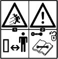
Caution, Warning, or Danger—personal safety instruction. Failure
to comply with these instructions may result in personal injury or
death.
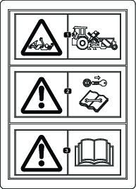
, which means
Caution, Warning, or Danger—personal safety instruction. Failure
to comply with these instructions may result in personal injury or
death.


Maintenance
Recommended Maintenance Schedule(s)
| Maintenance Service Interval | Maintenance Procedure |
|---|---|
| Before each use or daily |
|
| Every 50 hours |
|
| Every 100 hours |
|
| Yearly |
|
Maintenance Safety
-
Before adjusting, cleaning, servicing, or leaving the machine, do the following:
-
Position the machine on a level surface.
-
Move the throttle switch to the low-idle position.
-
Disengage the PTO (if applicable).
-
Ensure that the traction is in neutral.
-
Engage the parking brake.
-
Shut off the engine of the traction unit and remove the key.
-
Wait for all moving parts to stop.
-
Allow machine components to cool before performing maintenance.
-
-
Perform only those maintenance instructions described in this manual. If major repairs are ever needed or assistance is desired, contact an authorized Bullseye distributor.
-
Ensure that the machine is in safe operating condition by keeping nuts, bolts, and screws tight.
-
If possible, do not perform maintenance while the engine is running. Keep away from moving parts.
-
Carefully release pressure from components with stored energy.
-
Support the machine with blocks or storage stands when working beneath it. Never rely on the hydraulic system to support the machine.
-
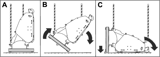
Never crawl under the attachment. If necessary, tilt the attachment.
-
Ensure that all guards are installed and secured after maintaining or adjusting the machine.
-
To ensure safe, optimal performance of the machine, use only genuine Bullseye replacement parts. Replacement parts made by other manufacturers could be dangerous, and such use could void the product warranty.
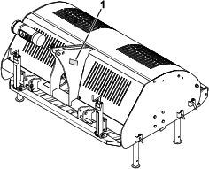
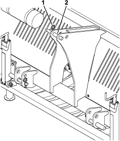
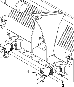
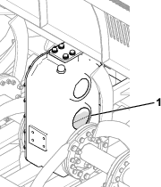
Opening the Hatch
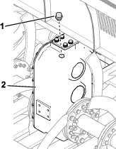
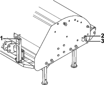
Checking the Gearbox Oil Level
| Maintenance Service Interval | Maintenance Procedure |
|---|---|
| Before each use or daily |
|
| Every 50 hours |
|
Gearbox-oil specification: SAE 90
-
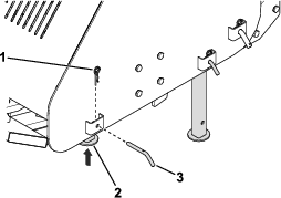
Open the hatch; refer to Opening the Hatch.
-
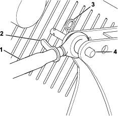
Check the oil level in the gearbox.
The gearbox oil level should be at or above the gauge centerline (Figure 30).
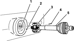
Servicing the PTO
| Maintenance Service Interval | Maintenance Procedure |
|---|---|
| Before each use or daily |
|
| Yearly |
|
-
Park the machine on a level surface, engage the parking brake, shut off the engine, and remove the key from the traction unit.
-
Secure the attachment from movement.
-
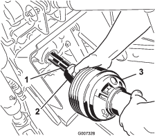
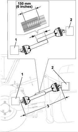
Disconnect the PTO from the traction unit and attachment.
-
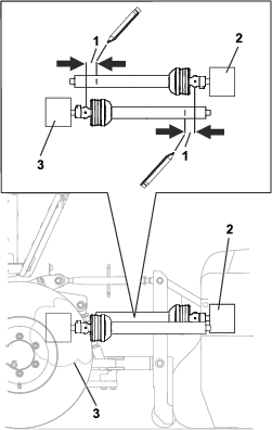
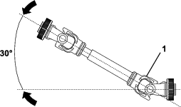
Inspect the PTO components for damage; replace any damaged or worn components.
-
Clean all interlocking components.
-
Reassemble the components.
-
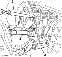
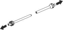
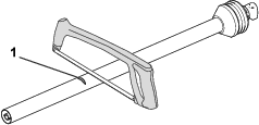
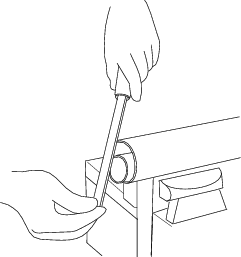
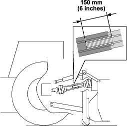
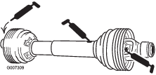
Grease the PTO shaft (Figure 31).
-
Grease the cylinders.
-
Assemble the PTO and mount it on the attachment.
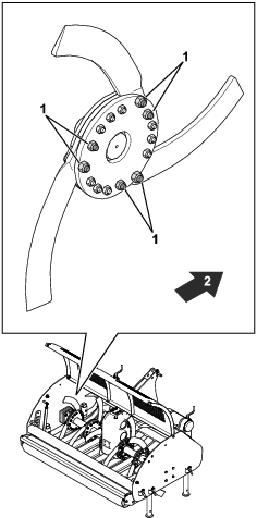
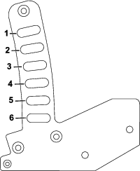
Checking the Knives
| Maintenance Service Interval | Maintenance Procedure |
|---|---|
| Every 100 hours |
|
Check to ensure that the knives are not damaged or crooked. You can use a hammer and an anvil to straighten them, if needed.
If the knives are beyond repair, replace them.
Washing the Attachment
| Maintenance Service Interval | Maintenance Procedure |
|---|---|
| Before each use or daily |
|
| Every 100 hours |
|
Wash the attachment as needed using compressed air, if possible. Use water as little as possible to clean the attachment. You may use a rag when washing the attachment.
Important: Do not use brackish or reclaimed water to clean the attachment.
Important: Do not use power-washing equipment to wash the attachment. Power-washing equipment may loosen important decals or wash away necessary grease at friction points.