


Maintenance
Maintenance Safety
-
Before cleaning, servicing, or adjusting the machine, do the following:
-
Park the machine on a level surface.
-
Wait for all moving parts to stop.
-
Remove the machine from the traction unit.
-
Lower the jack stand.
-
Allow machine components to cool before performing maintenance.
-
-
Perform only those maintenance instructions described in this manual. If major repairs are ever needed or you need assistance, contact an authorized Toro distributor.
-
Support the machine with blocks or jack stands when working beneath it.
-
Ensure that all guards are installed securely after maintaining or adjusting the machine.
-
Do not allow untrained personnel to service the machine.
-
Keep all parts in good working condition and all fasteners tightened. Replace all damaged or missing decals.
-
Do not interfere with the intended function of a safety device or reduce the protection provided by a safety device. Check their proper operation regularly.
-
If major repairs are ever necessary or assistance is required, contact an authorized Toro distributor.
-
Altering this machine in any manner may affect the operation of the machine, performance, durability, or its use may result in injury or death. Such use could void the product warranty of The Toro® Company.
Lubricating the Blower
| Maintenance Service Interval | Maintenance Procedure |
|---|---|
| Every 50 hours |
|
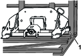
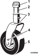
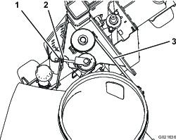
The debris blower has bearings and bushings that must be lubricated regularly. If the machine is operated under normal conditions, lubricate bearings with No. 2 lithium grease. Lubricate fittings immediately after every washing, regardless of the interval listed.
The lubrication points are as follows:
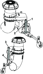
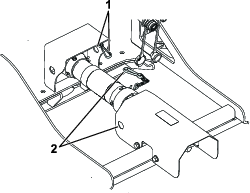
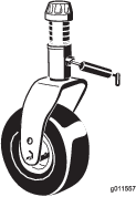
Drive pulley (Figure 21)
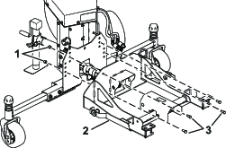
Castor wheel shaft (2) (Figure 22)
Lubricating the Driveshaft
| Maintenance Service Interval | Maintenance Procedure |
|---|---|
| Before each use or daily |
|
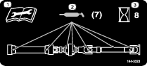
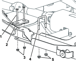
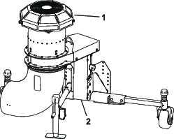
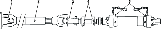
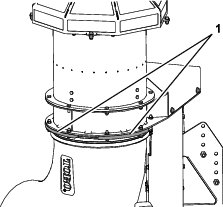
The mounting kit drive shaft has bearings and bushings that you must lubricate regularly. If you are operating the machine under normal conditions, lubricate bearings with No. 2 lithium grease. Lubricate fittings immediately after every washing, regardless of the interval listed.
-
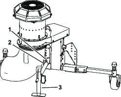
Position the machine and blower on a level surface and lower the blower.
-
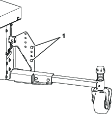
There are 7 grease points; refer to the mount kit service decal or Figure 23.
Checking the Gearbox Lubrication
| Maintenance Service Interval | Maintenance Procedure |
|---|---|
| Every 50 hours |
|
Gearbox capacity: 207ml (7 fl oz).
-
Position the machine and blower on a level surface and lower the blower.
-
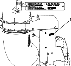
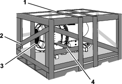
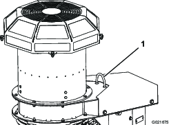
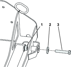
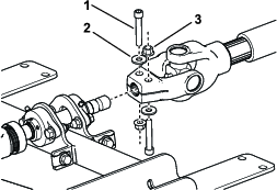
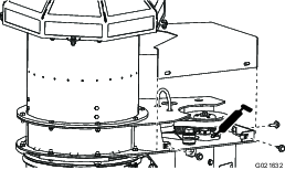
Remove the 5 bolts and washers securing the gear case cover to the blower (Figure 24).
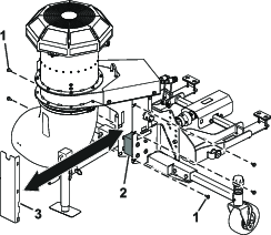
-
Remove the cover to expose the blower gear case (Figure 24).
-
Remove the check/fill plug from the side of the gearbox (Figure 25).
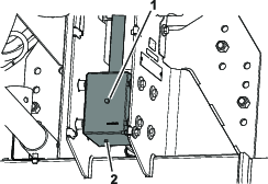
-
Check the oil level to make sure it is up to the plug hole in the gearbox. If the lubricant level is low, add enough SAE 80-90 weight gear lube to raise the level up to the hole.
-
Install the check/fill plug to the gearbox.
-
Install the cover.
Checking the Nozzle
| Maintenance Service Interval | Maintenance Procedure |
|---|---|
| Before each use or daily |
|
Checking the Nozzle Clamp and Adjusting Position
Warning
Discharged air has considerable force and could cause injury or loss of footing.
Park the traction unit on a level surface, disengage the PTO, remove the key, and wait for all moving parts to stop before adjusting the position of the blower nozzle.
-
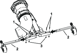
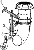
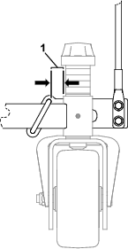
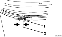
Check the nozzle clamp (Figure 26) daily to ensure that is tight.
Note: The nozzle can loosen if it is dragged over obstacles or through low areas in the terrain.
-
Tighten the clamp fasteners to maintain a gap of 1.3 cm (0.50 inch).
The nozzle should rotate freely when you move it by hand.
Cleaning the Nozzle Guides
Check and remove any grass, dirt or debris buildup around and in between the nozzle guides (Figure 27).
Keep the nozzle free of debris to prevent the motor from stalling.
Adjusting the Nozzle Belt
| Maintenance Service Interval | Maintenance Procedure |
|---|---|
| After the first 8 hours |
|
| Every 50 hours |
|
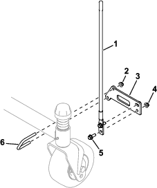
Adjust the belt if the belt slips when changing direction of the nozzle.
-
Press the belt, at the center of the longest span, with 30 N∙m (22 lb) of force (Figure 28).
Note: The belt should deflect 4.8 mm (0.19 inch).
-
If the deflection is incorrect, proceed to the next step. If it is correct, continue operation.
-
Loosen the hex nut and tighten the flange nut to increase the belt tension (Figure 28).
Note: Do not over tighten.
-
Tighten the hex nut to lock the adjustment.
Storage
-
Remove grass clippings, dirt, and grime from the external parts of the entire blower.
Important: You can wash the machine with mild detergent and water. Do not pressure wash the machine. Avoid excessive use of water.
-
Check and tighten all bolts and nuts. Replace any worn parts.
-
Paint all scratched or bare metal surfaces. Paint is available from your Authorized Service Dealer.
-
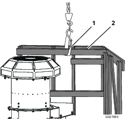
Store the machine in a clean, dry garage, or storage area. Use the jack stand to store the blower in the upright position. Do not lay the blower down on the ground.