Installation
Preparing the Machine
-
Park the machine on a level surface.
-
Engage the parking brake.
-
Lower the attachment.
-
Shut off the engine and remove the key.
Removing the Attachment
-
If you have an equipped attachment, remove it; refer to the removal instructions in your traction unit Operator’s Manual.
-
Use a cord or cable tie to secure the PTO shaft out of the working area.
Removing the Existing Hydraulic Line
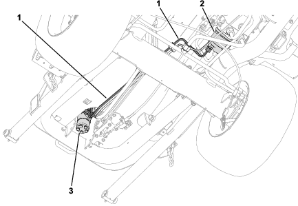
Remove the existing hard hydraulic line shown in Figure 1.
The hydraulic line is connected to the following ports:
-
Steering valve:
-
Hydraulic pump:
Installing the Hose
Parts needed for this procedure:
| Hydraulic hose | 1 |
| Straight fitting | 1 |
| 45° fitting | 1 |
-
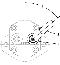
Remove the existing fitting from the hydraulic pump and replace it with the straight fitting.
-
Connect the 45° hydraulic-hose fitting to the new straight fitting and orient it at 50° as shown in Figure 2.
-
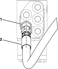
Remove the existing fitting from the steering valve and replace it with the 45° fitting and orient it downwards.
-
Connect the straight hydraulic-hose fitting to the new 45° fitting as shown in Figure 3.
-
Ensure that the hydraulic hose is routed as shown in Figure 4.
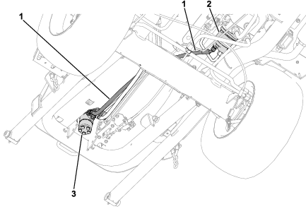
-
Ensure that the hose and fittings are aligned as shown in Figure 2 and Figure 3 and that there is no twist in the hose when routed next to the existing hydraulic lines.
Completing the Installation
-
Install an attachment; refer to the installation instructions in your traction unit Operator’s Manual.
-
Perform the following steps to purge air from the hydraulic system:
-
Fully lower and raise the attachment.
-
Cycle steering wheel all-the-way to the left and the right.
-