Introduction
The GeoLink® spray system kit is an attachment for a turf spray application vehicle and is intended to be used by professional, hired operators in commercial applications. It is designed primarily for spraying on well-maintained lawns in parks, golf courses, sports fields, and on commercial grounds.
Visit www.Toro.com for product safety and operation training materials, accessory information, help finding a dealer, or to register your product.
Safety
Warning
Chemical substances used in the spray system may be hazardous and toxic to you, bystanders, animals, plants, soils, or other property.
-
Carefully read and follow the chemical warning labels and safety data sheets (SDS) for all chemicals used and protect yourself according to the chemical manufacturer's recommendations. For example, use appropriate personal protective equipment (PPE), including face and eye protection, gloves, or other equipment to guard against personal contact with a chemical.
-
There may be more than 1 chemical used and information on each chemical should be assessed.
-
Refuse to operate or work on the sprayer if this information is not available.
-
Before working on a spray system, ensure that the system has been triple rinsed and neutralized according to the recommendations of the chemical manufacturer(s) and that all the valves have been cycled 3 times.
-
Verify that there is an adequate supply of clean water and soap nearby, and immediately wash off any chemicals that contact you.
Installation
Preparing to Install the Kit
Preparing the Sprayer Tank and Optional Rinse Tank
-
Park the machine on a level surface.
-
Engage the parking brake; refer to the Operator’s Manual.
-
Extend the left and right boom sections to the horizontal position.
-
Shut off the engine; refer to the Operator’s Manual.
-
Clean the sprayer; refer to Cleaning the Sprayer in the Operator’s Manual for the machine.
Important: You must completely empty the sprayer tank before installing the GeoLink Spray System Finishing Kit.
-
For machines with the optional tank-rinse kit, perform the following:
-
Pump the water from the rinse tank into the sprayer tank; refer to Operating the Rinse Kit in the Installation Instructions for the Tank-Rinse Kit.
-
Drain the water from the sprayer tank; refer to Cleaning the Sprayer in the Operator’s Manual for the machine.
-
-
Remove the key from the key switch; refer to the Operator’s Manual.
Disconnecting the Battery
-
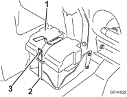
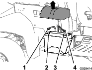
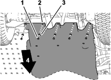
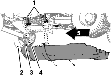
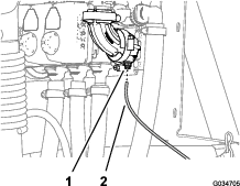
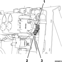
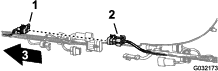
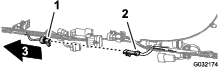
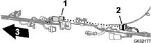
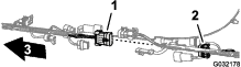
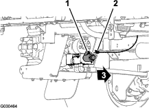
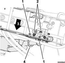
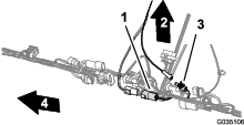
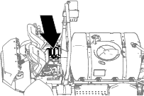
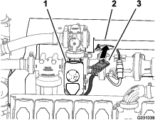
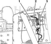
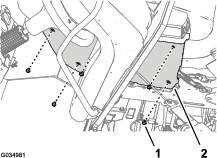
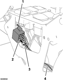
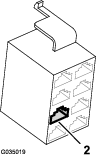
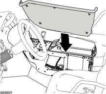
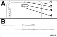
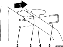
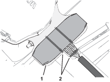
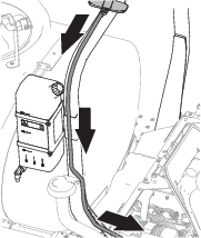
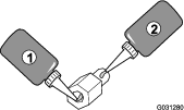
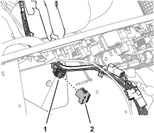
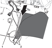
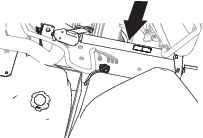
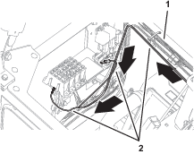
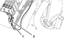
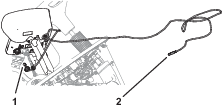
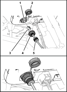
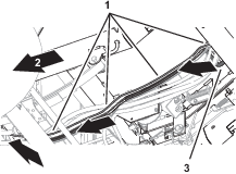
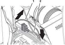
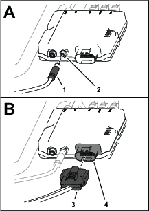
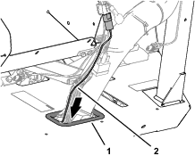
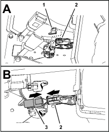
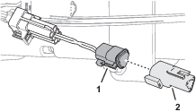
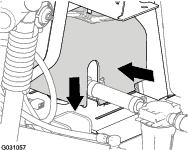
Remove the battery cover and disconnect the negative (black—ground) cable from the battery post (Figure 1 and Figure 2).
Warning
Electrical sparks can cause the battery gasses to explode, resulting in personal injury.
Incorrect battery cable routing could damage the sprayer and cables, causing sparks.
-
Always disconnect the negative (black) battery cable before disconnecting the positive (red) cable.
-
Always connect the positive (red) battery cable before connecting the negative (black) cable.
Battery terminals or metal tools could short against metal sprayer components, causing sparks.
-
When removing or installing the battery, do not allow the battery terminals to touch any metal parts of the sprayer.
-
Do not allow metal tools to short between the battery terminals and metal parts of the sprayer.
-
Always keep the battery strap in place to protect and secure the battery.
-
-
Disconnect the positive (red) cable from the battery post (Figure 2).
-
Tilt both seats forward and secure them by moving the prop rods into the detents at the end of the slots at the center-console base.
-
Allow the engine to cool completely.
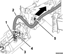
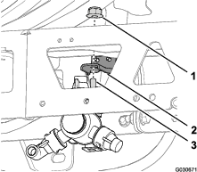
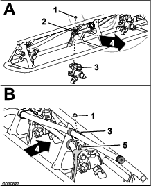
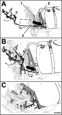
Disconnecting the Rear Wire Harness from the Optional Attachments
Disconnecting the Pivoting Hose-Reel Kit
-
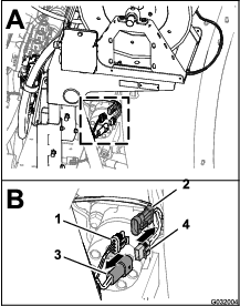
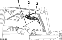
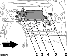
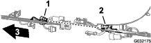
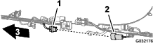
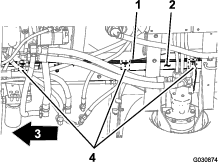
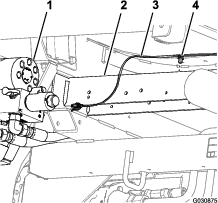
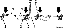
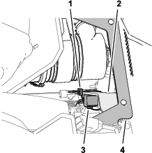
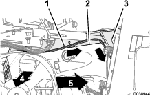
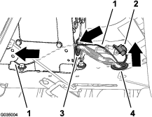
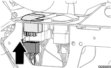
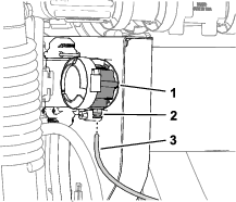
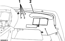
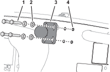
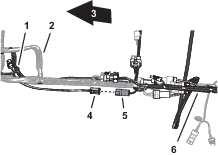
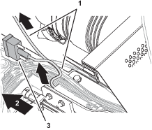
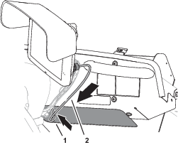
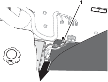
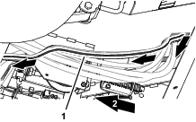
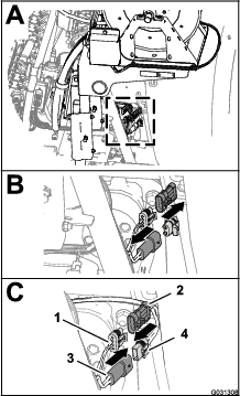
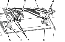
At the back of the machine, locate the wire harness for the electric-hose-reel kit at the back of the sprayer tank (A in Figure 3).
-
Disconnect the 2-socket connector of the harness for the electric-hose reel from the 2-pin connector of the rear-main harness (B in Figure 3).
-
Disconnect the 3-pin connector of the harness for the electric-hose reel from the 3-pin socket of the rear-main harness (B in Figure 3).
Disconnecting the Compressor for the Foam-Marker Kit
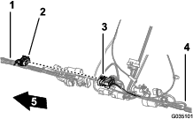
Disconnecting the Pump for the Tank-Rinse Kit
-
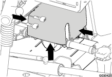
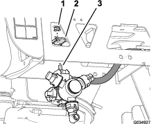
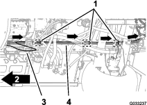
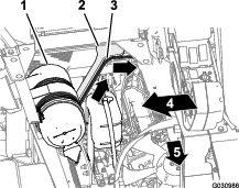
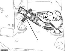
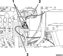
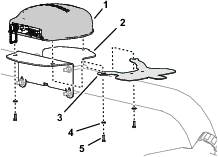
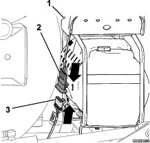
At the back of the machine, press together the sides of the rinse-pump cover and lift the cover up until the tabs of the cover clear the slots in the saddle plate, and remove the cover from the machine (Figure 5).
-
Disconnect the 6-pin connector of the rinse-pump harness from the 6-socket connector of the rear, main harness (Figure 6).
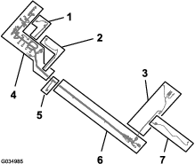
Removing the Pressure Control Switch—Optional Pivoting Hose-Reel Kit
Parts needed for this procedure:
| Switch plug (pivoting hose-reel kit—Toro Part No. 99-7420) | 1 |
-
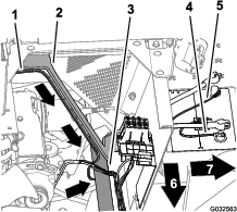
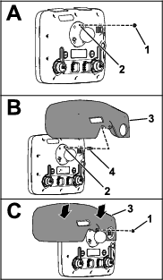
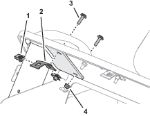
Remove the 2 bolts (5/16 x 3/4 inch) and 2 locknuts (5/16 inch) that secure the control box to the reel-mounting plate (Figure 7).
-
Disconnect the 8-socket connector for the control box harness from the PRESSURE-CONTROL switch (Figure 7).
-
Route the 8-socket connector inside the control box (Figure 7).
-
Squeeze the lock tabs of the PRESSURE-CONTROL switch and press the switch out of the control box (Figure 7).
Note: You no longer need the switch that you removed from the machine.
-
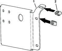
Align the switch plug to the opening in the control box where you removed the switch (Figure 7).
-
Insert the switch plug into the control box until the plug snaps into the cover securely (Figure 7).
-
Align the control box to the reel-mounting plate (Figure 7) and secure the box to the plate with the 2 bolts (5/16 x 3/4 inch) and 2 locknuts (5/16 inch).
-
Torque the bolts and nuts to 1978 to 2542 N·cm (175 to 225 in-lb).
Removing the Undercarriage Shroud
-
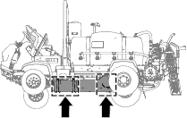
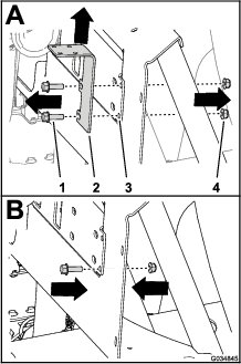
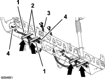
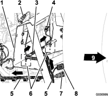
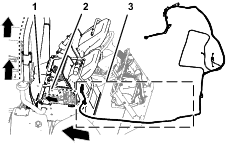
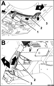
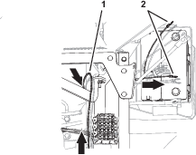
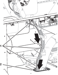
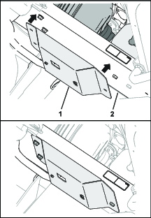
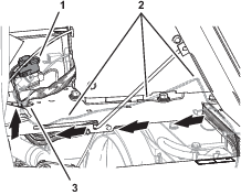
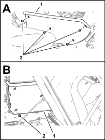
Remove the following hardware that secures the rear of the undercarriage shroud to the chassis of the machine (Figure 8):
-
2016 machines—7 flange-head bolts (5/16 x 7/8 inch) and 7 washers (5/16 inch)
-
2017 and later machines—5 flange-head bolts (5/16 x 7/8 inch) and 5 washers (5/16 inch)
Note: Retain the flange-head bolts and washers for installation in step 5 of Installing the Undercarriage Shroud.
-
-
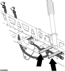
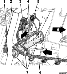
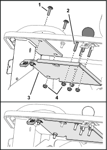
Remove the 4 flange locknuts (5/16 inch) from the bolts and carriage bolt that secure the support straps of the undercarriage shroud to the engine-mount brackets of the machine (Figure 9).
Note: Do not remove the bolts from the machine. Retain the flange locknuts for installation in step 3 of Installing the Undercarriage Shroud.
-
Lift the support straps over the bolts that secure the undercarriage shroud to the engine-mount brackets.
-
Remove the undercarriage shroud from the machine (Figure 8 and Figure 9).
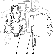
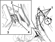
Removing the Engine-Control Module and Mounting Bracket (Machine Models with a Gasoline Engine)
-
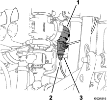
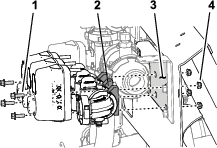
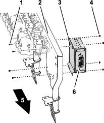
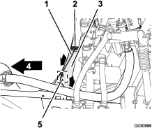
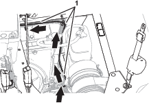
Remove the 3 flange head bolts and 1 flange nut that secure the mounting bracket for the engine-control module to the support bracket of the engine and accessory case of the engine (Figure 10).
Note: Retain the flange-head bolts and flange nut for installation in step 2 of Installing the Engine-Control Module and Mounting Bracket (Machine Models with a Gasoline Engine).
-
Move the engine-control module and mounting bracket down and rearward to provide access to the connectors of the front and rear wiring harnesses for the machine.
Note: Do not remove or disconnect the engine-control module from the engine.
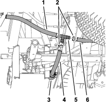
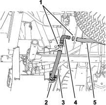
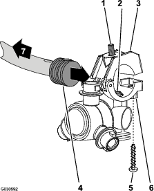
Disconnecting the Pressure-Sense Tube for the Dash Gauge
Disconnecting the Pressure-Sense Tube for the Dash Gauge—Machines Without an Optional Hose Reel Kit
Note: If your machine is equipped with an optional spray gun kit, refer to Disconnecting Pressure-Sense Tube and Supply Hose—Optional Spray Gun Kit or Optional Pivoting Hose Reel Kit.
Disconnecting Pressure-Sense Tube and Supply Hose—Optional Spray Gun Kit or Optional Pivoting Hose Reel Kit
-
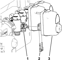
Press in the collar for the tube coupler in the 90° elbow of the right boom-section valve (Figure 12 or Figure 13).
-
Pull the pressure-sense tube for the dash pressure gauge out of the tube coupler (Figure 12 or Figure 13).
Note: Do not remove the 90° elbow from the flange of the right boom-section valve.
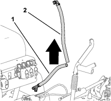
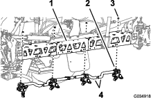
Removing the Rear Wire Harness for the Machine
Parts needed for this procedure:
| Rear wire harness | 1 |
Disconnecting the Front and Rear Wire Harnesses
Note: Use a machine hoist when disconnecting the front and rear wire harnesses.
-
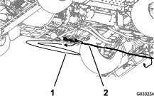
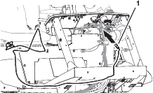
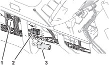
From under the machine along the right frame tube, locate the electrical connectors for the front and rear wire harnesses of the machine (Figure 14).
-
Disconnect the 6 pairs of connectors between the front and rear wire harnesses as shown in Figure 15 through Figure 20.
-
Remove the 3 push-in fasteners that secure the rear wire harness to the holes in the right frame tube of the machine (Figure 21).
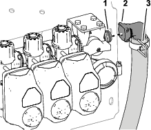
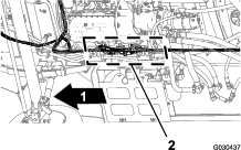
Disconnecting the Connectors for the Components
-
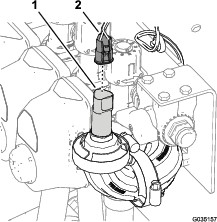
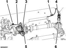
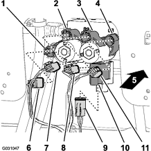
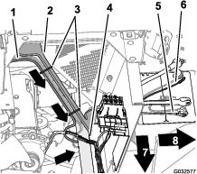
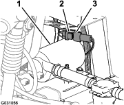
At back of the machine (between the right frame tube and the right fender) disconnect the 3-pin connector of the speed-sensor harness at the right hydraulic-traction motor from the 3-socket connector of the rear, main harness (Figure 22).
-
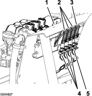
At the back of the manifold mount, disconnect the 3-socket connector from the agitation valve and the 3-socket connectors from the 3 boom-section valves (Figure 23).
-
Remove the push-in fasteners that secure the rear wire harness to the holes at the forward side and lower plate of the manifold mount (Figure 24).
-
For machines with the ExcelaRate sprayer system, disconnect the 3-socket connector of the rear-wire-harness from the 3-pin connector of the pressure transducer (Figure 25).
-
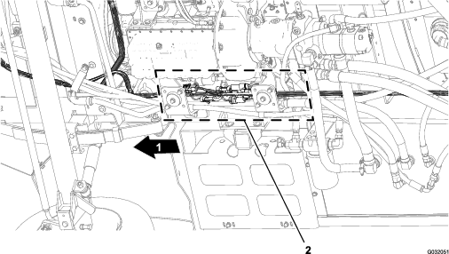
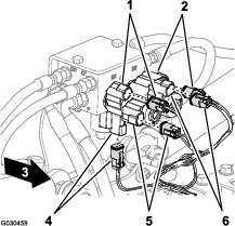
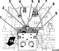
At the back of the machine, disconnect the following 2-socket connectors (Figure 26) for the lift-cylinder manifold as follows:
-
Right—up solenoid
-
Left—up solenoid
-
Enable solenoid
-
Right—down solenoid
-
Left—down solenoid
-
-
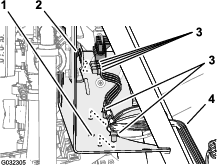
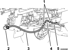
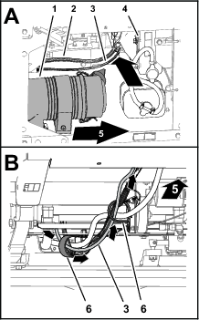
At the back of the machine—inboard of the sprayer pump, disconnect the 2-socket connector of the rear, main harness from the 2-pin connector of the relay for the pump (Figure 27).
-
Remove the push-in fastener that secures the rear wire harness (Figure 28) to the holes in the rear cross tube (rearward of the hydraulic-traction motors).
-
Remove the pressure-sense tube for the dash gauge from the rear wire harness from the machine (Figure 29).
-
Remove the rear wire harness from the machine.
Note: You no longer need the rear-main harness that you removed from the machine.
Removing the Rate-Control Switch
Parts needed for this procedure:
| Cable tie | 1 |
| Switch plug | 1 |
-
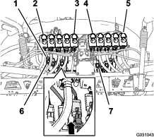
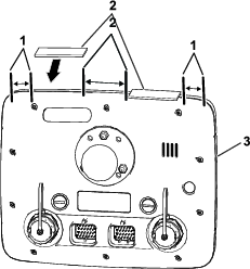
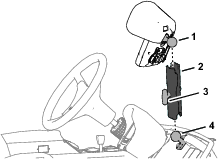
From under the dash panel of the machine, squeeze the lock tabs of the rate-control switch together and push up the rate-control switch out of the dash panel (Figure 30).
-
Disconnect the 8-socket connector of the front harness of the machine (labeled Rate Switch) from the 8-pin connector of the switch (Figure 30).
Note: You no longer need the rate switch that you removed from the machine.
-
Route the branch of the front harness for the rate switch through the opening in the dash and secure the wiring branch against the front harness with a cable tie.
-
Align the switch plug to the opening in the dash panel where you removed the rate switch (Figure 30).
-
Insert the switch plug into the dash panel until the plug snaps into the panel securely (Figure 30).
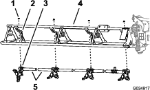
Removing the Boom-Section Valves
Parts needed for this procedure:
| Fitting cap | 1 |
| Cap (quick coupler) | 3 |
| Retainer | 3 |
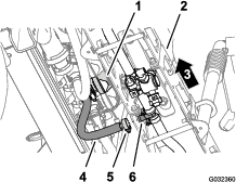
Removing the Pressure Transducer from the Section Valve
-
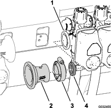
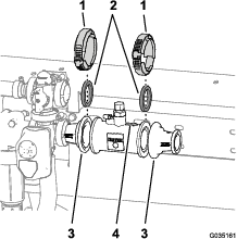
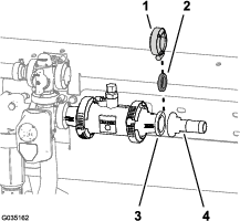
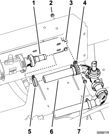
Remove the flange clamp that secures the ported-fitting cap, pressure transducer, and gasket to the 90° elbow at the end of the right-section valve, and remove the cap, transducer, and gasket (Figure 31).
Note: Retain the pressure transducer and ported-fitting cap, gasket, and clamp for installation in Assembling the Pressure Transducer to the Manifold.
-
Remove the flange clamp, 90° elbow (non-ported),and gasket from the ported 90° elbow (Figure 31).
Note: Retain the flange clamp and gasket for installation in 3.
-
Align the fitting cap , and gasket to the flange of the 90° elbow at the end of the right-section valve (Figure 31).
-
Secure the fitting cap and gasket to the 90° elbow with the flange clamp (Figure 31).
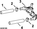
Removing the Coupling Tube and Reducer Adapter
-
Loosen the 4 flange-head bolts (1/4 x 3/4 inch) and 4 flange locknuts (1/4 inch) that secure the 3 section valves to the manifold mount (Figure 33).
-
For machines without the ExcelaRate sprayer system, remove the coupling tube as follows:
-
Remove the 2 flange clamps that secure the coupling tube to the reducer adapters at the at the master-control valve and left boom-section valve (Figure 34).
-
Remove the straight coupler and 2 gaskets from the machine (Figure 34).
Note: Retain clamps and gaskets for installation in steps 11 and 12 of Assembling the Flow Meter.
-
Remove the flange clamp 76 mm (3 inches) that secures the reducer adapter and gasket (2-1/4 inches) to the flange of the left boom-section valve, and remove the adapter, clamp and gasket from the machine (Figure 35).
Note: Retain reducer adapter for installation in steps 13 of Assembling the Flow Meter.
-
-
For machines with the ExcelaRate sprayer system, remove the flange clamp and gasket that secures the reducer adapter to the left boom-section valve (Figure 36).
Note: Do not remove the reducer adapter or the flow meter.
Removing the Boom-Section Hoses
-
At the outer-boom section, remove the hose clamp that secures the supply hose for the boom section to the barbed T-fitting (Figure 37).
-
Remove the hose from the T-fitting (Figure 37).
-
Remove the free end of the hose from the R-clamp (Figure 37).
-
Repeat steps 1 through 3 for the supply hose at the other outer-boom section.
-
Under the center-boom section, remove the hose clamp that secures the supply hose for the boom section to the barbed T-fitting (Figure 38).
-
Remove the retainers that secure the straight barbed fittings to the quick disconnect fittings of the left, center, and right boom-section valves (Figure 39).
Note: Retain the retainers for installation in Assembling the Hoses to Nozzle Valves 7 through 10.
-
Remove the hoses for the left, center, and right boom-section valves from the machine (Figure 39).
Note: You no longer need the hoses for the left, center, and right boom-section valves.
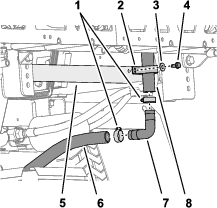
Removing the Bypass Hoses
-
At the lower end of the upper bypass hose, remove the flange-head bolt (5/16 x 3/4 inch), washer (5/16 inch), and R-clamp that secures the upper bypass hose to the rear-saddle plate of the machine (Figure 40 and Figure 41).
-
Remove the 2 hose clamps that secure the upper bypass hose and the lower bypass hose to the 90° barbed fitting (Figure 41).
-
Remove the 90° barbed fitting from the hoses (Figure 41).
Note: Retain the 90° barbed fitting and 2 clamps for installation in steps 8 and 9.
-
Remove the hose clamps that secure the drain-valve hose and the rear tank-drain hose to the barbed T-fitting (Figure 42 and Figure 43).
-
Remove the T-fitting from the drain-valve hose from the rear tank-drain hose (Figure 42 and Figure 43).
-
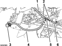
Remove the retainer that secures the 90° barbed fitting of the bypass hose to the quick-disconnect fitting of the bypass valve at the right boom-section valve, and separate the hose and valve fittings (Figure 44).
-
Remove the upper and lower bypass hoses from the machine (Figure 45).
Note: You no longer need the shutoff valve, T-fitting, upper bypass hose, and lower bypass hose.
-
Insert the 90° barbed fitting that you removed in step 3 into the drain-valve hose and the rear tank-drain hose (Figure 46 and Figure 47).
-
Secure the 90° barbed fitting and drain hoses with the 2 hose clamps that you removed in step 2 (Figure 46 and Figure 47).
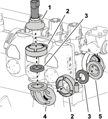
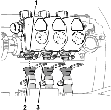
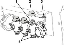
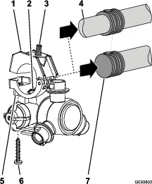
Removing the Valve Actuator
-
Remove the retainer that secures the actuator to the manifold valve of the section valve assembly(Figure 48).
Note: Squeeze the 2 legs of the retainer together while pushing it down.
Note: Retain the actuator and retainer for installation in steps 8 and 9 of Removing the Bypass Shutoff Valve and Installing the Bypass Valve with Caps.
-
Remove the actuator from the manifold valve (Figure 48).
-
Repeat steps 1 and 2 for the 2 other valve actuators.
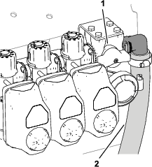
Removing the Bypass Shutoff Valve and Installing the Bypass Valve with Caps
-
Remove the 4 bolts (6 x 12 mm) that secure the bypass-shutoff valve to the valve-support bracket (Figure 49).
-
Remove the retainer that secures the bypass-shutoff valve to the bypass valve for the right boom section valve, and remove the shutoff valve (Figure 49).
Note: You no longer need the bypass-shutoff valve and the 4 bolts (6 x 12 mm).
-
Remove the 3 retainers that secure the 3 bypass valves to the 3 manifold valves (Figure 49).
-
Lift the 3 bypass valves from the 3 quick couplers of the manifold valves (Figure 49).
Note: You no longer need the bypass valves.
-
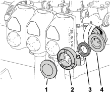
Lubricate the upper and lower O-rings on the quick coupler of the manifold valve with the grease provided with the quick-coupler cap (Figure 50).
-
Assemble the 3 caps for the quick couplers onto the 3 quick couplers for the manifold valves (Figure 50).
-
Secure the 3 caps to the 3 quick couplers with the 3 retainers (Figure 50).
-
Align the coupler of the section valve actuator that you removed in step 2 of Removing the Valve Actuator with the stem port of the manifold valve (Figure 51).
-
Secure the section valve actuator to the manifold valve with a retainer (Figure 51) that you removed in step 1 of Removing the Valve Actuator.
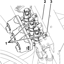
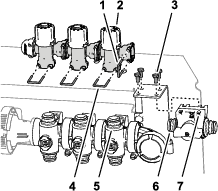
Disassembling the Boom-Section Valves from the Manifold Mount
Note: You will add the boom-section valves to the valves for the 10-valve system in Assembling Sprayer Valves 8, 9, and 10 to the Valve Mount.
-
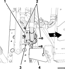
Remove the 2 flange-head bolts (1/4 x 3/4 inch) and 2 locknuts (1/4 inch) that secure the right boom-section valve to the manifold mount (Figure 52).
-
Remove the 2 flange-head bolts (1/4 x 3/4 inch) and 2 locknuts (1/4 inch) that secure the left boom-section valve to the manifold mount (Figure 52).
-
Remove the boom-section valves from the manifold mount and set aside the valves (Figure 52).
Note: Retrain the boom-section valves for installation in steps 1 of Assembling Sprayer Valves 8, 9, and 10 to the Valve Mount. Discard the 4 flange-head bolts and 4 locknuts.
-
Remove the 6 decals from the 3 boom-section valves (Figure 53).
-
Remove the 2 flange-head bolts (5/16 x 1 inch) and 2 flange locknuts (5/16 inch) that secure the support bracket for the bypass-shutoff valve to the manifold mount (A of Figure 54), and remove the shutoff-valve bracket.
-
Assemble a flange-head bolt (5/16 x 1 inch) and flange locknut (5/16 inch) to the manifold mount (B of Figure 54) at the lower hole position for the shutoff-valve bracket that you removed in step 5.
Note: Retain the other flange-head bolt and flange locknut for installation in step 3 of Installing the Pressure Transducer onto the Machine.
-
Torque the flange bolt and flange nut to 1978 to 2542 N·cm (175 to 225 in-lb).
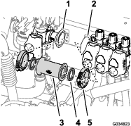
Installing the Flow Meter and Pressure Transducer
Parts needed for this procedure:
| Flow meter (for 2016 machines without the ExcelaRate sprayer system only)—not included in this kit; order Toro Part No. 106-1038. | 1 |
| Flange clamp 51 mm (2 inches) | 1 |
| Gasket (1-5/16 inch outside diameter) | 1 |
| Barbed-flange fitting (1 inch) | 1 |
| Hose (1 x 7-1/4 inches) | 1 |
| Hose clamp | 3 |
| Pressure transducer (for 2016 machines without the ExcelaRate sprayer system only)—not included in this kit; order Toro Part No. 130-8202. | 1 |
| Fitting cap—ported (for 2016 machines without the ExcelaRate sprayer system only)—not included in this kit; order Toro Part No. 127-1185. | 1 |
| Manifold | 1 |
| Hose (1 x 8-1/2 inches) | 1 |
| R-clamp | 1 |
Assembling the Flow Meter
-
For machines without the ExcelaRate sprayer system, perform the following steps:
-
Align the gasket (2-1/4 inches) that you removed in step 22 of Removing the Coupling Tube and Reducer Adapter between the flow meter and the reducer adapter that is installed at the right side of the master-control valve (Figure 55).
-
Loosely assemble the gasket, flow meter, and reducer adapter (Figure 55) with a flange clamp 76 mm (3 inches) that you removed in step 21 of Removing the Coupling Tube and Reducer Adapter.
-
Align the gasket (2-1/4 inches) and reducer adapter that you removed in step 23 of Removing the Coupling Tube and Reducer Adapter to the end of the flow meter to which the directional arrow points (Figure 55).
-
Assemble the gasket, flow meter, and reducer adapter (Figure 55) with a flange clamp 76 mm (3 inches) that you removed in step 21 of Removing the Coupling Tube and Reducer Adapter.
-
-
Align the gasket (1-5/16 inch) that you removed in step and barbed hose fitting to the end of the reducer adapter (Figure 56).
-
Secure the hose fitting and gasket to the adapter (Figure 56) with the flange clamp 51 mm (2 inches).
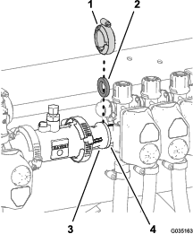
Assembling the Pressure Transducer to the Manifold
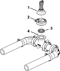
Installing the Pressure-Transducer Manifold
-
Assemble the hose (1 x 7-1/4 inches) onto the barbed elbow fitting of the pressure transducer and manifold as shown in Figure 58.
-
Secure the hose and barbed fittings with a hose clamp (Figure 58).
-
Assemble the hose (1 x 8-1/2 inches) onto the other barbed elbow-fitting of the pressure transducer and manifold as shown in Figure 58.
-
Secure the hose and barbed fitting with a hose clamp (Figure 58).
Installing the Pressure Transducer onto the Machine
-
Assemble the hose (1 x 7-1/4 inches) that is attached to the pressure transducer and manifold (Figure 59) onto the barbed-flange fitting (1 inch).
-
Loosely secure the hose to the barbed-flange fitting with a hose clamp (Figure 59).
Note: You will tighten the hose clamp at the left end of the hose (1 x 7-1/4 inches) in Assembling the Hose to the Sprayer Valve Manifold.
-
Secure the pressure transducer and manifold to the slot in the manifold mount with a R-clamp (Figure 59) and the flange-head bolt (1/4 x 3/4 inch), and flange locknut (1/4 inch) that you removed in step 5 of Disassembling the Boom-Section Valves from the Manifold Mount.
Installing the Valve Mount and Sprayer Valves
Parts needed for this procedure:
| Valve mount and sprayer-valve assembly | 1 |
| Bolt (4 x 10 mm) | 4 |
| Sprayer controller—GeoLink precision spray system kit (Model 41633 or Model 41634) | 1 |
| Flange locknut (4 mm) | 4 |
| Flange-head bolts (5/16 x 3/4 inch) | 8 |
| Flange locknuts (5/16 inch) | 8 |
| Hose clamp | 1 |
| Flange head bolt (1/4 x 3/4 inch) | 2 |
| Flange locknut (1/4 inch) | 2 |
Assembling the Sprayer Controller to the Valve Mount
Assembling the Valve Mount and Sprayer Valve Assembly to the Machine
Lifting-equipment capacity: 23 kg (50 lb)
-
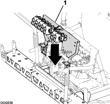
Using lifting equipment with the specified capacity, lift the valve mount and sprayer valve assembly and align it over the center-boom section (Figure 61).
-
Align the holes on the mount bracket of the valve mount to the holes on the truss frame of the center-boom section (Figure 62).
-
Assemble the valve mount to the truss frame (Figure 62 and Figure 63) with 4 bolts (5/16 x 3/4 inch) and 4 flange locknuts (5/16 inch).
-
Repeat steps 2 through 3 for the other mount bracket of the valve mount at the other truss frame.
-
Torque the flange-head bolts and flange locknuts to 1978 to 2542 N∙cm (175 to 225 in-lb).
Assembling the Hose to the Sprayer Valve Manifold
-
Assemble the hose (1 x 8-1/2 inches) over the 90° flange fitting (1 inch) as shown in Figure 64.
-
Secure the hose to the flange fitting with a hose clamp (Figure 64).
-
Tighten the hose clamp that secures the hose (1 x 7-1/4 inches) to the barbed-flange fitting (1 inch) that you assembled in Installing the Pressure Transducer onto the Machine; refer to Figure 64.
Assembling Sprayer Valves 8, 9, and 10 to the Valve Mount
Important: The left boom-section valve that you removed in step 3 of Disassembling the Boom-Section Valves from the Manifold Mount is identified as nozzle-valve 8, the center boom-section valve is identified as nozzle-valve 9, and the right boom-section valve is identified as nozzle-valve 10 for the remainder of the GeoLink finishing kit installation instructions.
-
Align the gasket and the flange of the left section valve (identified as nozzle-valve 8) with the flange of nozzle-valve 7 (Figure 65).
-
Loosely secure the gasket and nozzle-valve 8 to nozzle valve 7 with a flange clamp (Figure 65).
-
Assemble nozzle-valve 10 to the valve mount (Figure 66) with the 2 flange-head bolts (1/4 x 3/4 inch) and 2 flange locknuts (1/4 inch) that you removed in step 2 of Disassembling the Boom-Section Valves from the Manifold Mount.
-
Torque the flange-head bolt and locknut to 1017 to 1234 N∙cm (90 to 120 in-lb).
-
Tighten the flange clamp by hand.
Removing the Sprayer-Nozzle Hoses for the 3-Section System
-
At the outer-boom section, cut the hose between 2 sprayer nozzles (Figure 67).
-
Remove the flange locknut (5/16 inch) that secures the sprayer nozzle to the nozzle support (Figure 67).
-
Repeat steps 2 and 6 for the other 3 nozzles.
Note: The hex-head bolt (5/16 x 3/4 inch—stainless steel) will separate from the upper clamp half when you open the clamp, retain the bolt for installation.
Note: Retain the flange locknut and sprayer nozzle for installation in Installing the Sprayer Nozzles at the Outer-Boom Sections.
Note: You no longer need the hose barbs and cut sections of hose.
-
Repeat steps 2 through 3 at the other outer-boom section.
-
At the center-boom section, cut the hose between 2 sprayer nozzles (Figure 67).
-
Remove the flange locknut (5/16 inch) that secures the sprayer nozzle to the nozzle support (Figure 68).
-
Repeat steps 2 and 6 for the other 3 nozzles.
-
Working with the 12 sprayer nozzles that you removed from the outer- and center-boom sections, remove the stainless steel screws (#12 x 1-1/4 inches) that secures the upper clamp halves and the double or single barbed-hose shanks (3/4 inch) to the body of each of the sprayer nozzle, and remove the barbed-hose shanks (Figure 70).
Note: The hex-head bolt (5/16 x 3/4 inch—stainless steel) will separate from the upper clamp half when you open the clamp, retain the bolt for installation.
Note: Retain the flange locknut and sprayer nozzle for installation in Installing the Sprayer Nozzles at the Center-Boom Sections.
Note: You no longer need the hose barbs and cut sections of hose.
Installing the Sprayer-Nozzle Hoses
Parts needed for this procedure:
| Supply hose 279 cm (110 inches) | 2 |
| Supply hose 234 cm (92 inches) | 2 |
| Supply hose 188 cm (74 inches) | 4 |
| Supply hose 81 cm (32 inches) | 2 |
| R-clamp | 2 |
| Double R-clamp | 2 |
| Single R-clamp | 2 |
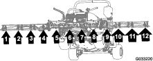
Identifying the Sprayer-Nozzle Hose Positions
Identify the supply hoses by length (Figure 71) for each of the sprayer-nozzle position as follows:
| Sprayer-nozzle positions—left-boom section | Sprayer-nozzle positions—center-boom section | Sprayer-nozzle positions—right-boom section |
|---|---|---|
| Sprayer nozzle 1 (nozzle valve 1)—supply hose 279 cm (110 inches) | Sprayer nozzles 5 and 6 (nozzle valve 5)—supply hose 81 cm (32 inches) with 2 branch hoses | Sprayer nozzle 9 (nozzle valve 7)—supply hose 188 cm (74 inches) |
| Sprayer nozzle 2 (nozzle valve 2)—supply hose 234 cm (92 inches) | Sprayer nozzles 7 and 8 (nozzle valve 6)—supply hose 81 cm (32 inches) with 2 branch hoses | Sprayer nozzle 10 (nozzle valve 8)—supply hose 188 cm (74 inches) |
| Sprayer nozzle 3 (nozzle valve 3)—supply hose 188 cm (74 inches) | Sprayer nozzle 11 (nozzle valve 9)—supply hose 234 cm (92 inches) | |
| Sprayer nozzle 4 (nozzle valve 4)—supply hose 188 cm (74 inches) | Sprayer nozzle 12 (nozzle valve 10)—supply hose 279 cm (110 inches) |
Note: Refer to Figure 72 in Assembling the Hoses to Nozzle Valves 1 through 4, Figure 73 in Assembling the Hoses to Nozzle Valves 5 and 6, and Figure 74 in Assembling the Hoses to Nozzle Valves 7 through 10 for the nozzle-valve positions.
Assembling the Hoses to Nozzle Valves 1 through 4
-
Assemble the straight barbed fitting of a supply hose 279 cm (110 inches) onto the coupler of nozzle valve 1 (Figure 72).
Note: Ensure that the barbed fitting is fully seated onto the coupler.
-
Secure the barbed fitting to the coupler with a retainer (Figure 72).
-
Assemble the straight barbed fitting of a supply hose 234 cm (92 inches) onto the coupler of nozzle valve 2 (Figure 72).
Note: Ensure that the barbed fitting is fully seated onto the coupler.
-
Secure the barbed fitting to the coupler with a retainer (Figure 72).
-
Assemble the straight barbed fitting of a supply hose 188 cm (74 inches) onto the coupler of nozzle valve 3 (Figure 72).
Note: Ensure that the barbed fitting is fully seated onto the coupler.
-
Secure the barbed fitting to the coupler with a retainer (Figure 72).
-
Assemble the straight barbed fitting of a supply hose 188 cm (74 inches) onto the coupler of nozzle valve 4 (Figure 72).
Note: Ensure that the barbed fitting is fully seated onto the coupler.
-
Secure the barbed fitting to the coupler with a retainer (Figure 72).
Assembling the Hoses to Nozzle Valves 5 and 6
Note: Supply hose assembly 81 cm (32 inches) has a T-fitting with 2 branch hoses and 2 single barbed-hose shanks.
-
Assemble the straight barbed fitting of a supply hose 81 cm (32 inches) onto the coupler of nozzle valve 5 (Figure 73).
Note: Ensure that the barbed fitting is fully seated onto the coupler.
-
Secure the barbed fitting to the coupler with a retainer (Figure 73).
-
Assemble the straight barbed fitting of a supply hose 81 cm (32 inches) onto the coupler of nozzle valve 6 (Figure 73).
Note: Ensure that the barbed fitting is fully seated onto the coupler.
-
Secure the barbed fitting to the coupler with a retainer (Figure 73).
Assembling the Hoses to Nozzle Valves 7 through 10
-
Assemble the straight barbed fitting of a supply hose 188 cm (74 inches) onto the coupler of nozzle valve 7 (Figure 74).
Note: Ensure that the barbed fitting is fully seated onto the coupler.
-
Secure the barbed fitting to the coupler with a retainer (Figure 74).
-
Assemble the straight barbed fitting of a supply hose 188 cm (74 inches) onto the coupler of nozzle valve 8 (Figure 74).
Note: Ensure that the barbed fitting is fully seated onto the coupler.
-
Secure the barbed fitting to the coupler with a retainer (Figure 74).
-
Assemble the straight barbed fitting of a supply hose 234 cm (92 inches) onto the coupler of nozzle valve 9 (Figure 74).
Note: Ensure that the barbed fitting is fully seated onto the coupler.
-
Secure the barbed fitting to the coupler with a retainer (Figure 74).
-
Assemble the straight barbed fitting of a supply hose 279 cm (110 inches) onto the coupler of nozzle valve 10 (Figure 74).
Note: Ensure that the barbed fitting is fully seated onto the coupler.
-
Secure the barbed fitting to the coupler with a retainer (Figure 74).
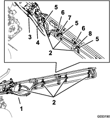
Routing the Supply Hoses at the Outer-Boom Sections
-
Route the hoses for sprayer nozzles 1, 2, 3, and 4 through the R-clamp at the left outboard end of the center-boom section (Figure 75 and Figure 76).
-
Route the hoses for sprayer nozzles 7, 8, 9, and 10 through the R-clamp at the right outboard end of the center-boom section (Figure 75 and Figure 76).
-
Route the supply hoses 279 cm (110 inches) and barbed-hose shanks (3/4 inch) along the boom section to sprayer nozzles 1 and 10 as shown in (Figure 75 and Figure 76).
-
Route the supply hoses 234 cm (92 inches) and barbed-hose shanks (3/4 inch) along the boom section to sprayer nozzles 2 and 9 along the boom section as shown in Figure 75 and Figure 76.
-
Route the supply hoses 188 cm (74 inches) and barbed-hose shanks (3/4 inch) along the boom section to sprayer nozzles 3 and 8 as shown in Figure 75 and Figure 76.
Note: Route the hoses through the lower rear grommets in the tube-frame brackets.
-
Route the supply hoses 188 cm (74 inches) and barbed-hose shanks (3/4 inch) along the boom section to sprayer nozzles 4 and 7 as shown in Figure 75 and Figure 76.
Note: Route the hoses through the lower rear grommets in the tube-frame brackets.
-
Bundle the 4 hoses for the sprayer nozzles together with a cable tie as shown in Figure 76.
Installing the Sprayer Nozzles at the Outer-Boom Sections
-
Working with the sprayer nozzle that you removed in Removing the Sprayer-Nozzle Hoses for the 3-Section System, align the transfer tube in the saddle of a sprayer nozzle (Figure 77) with the hole in the side of the single barbed-hose shank (1/2 inch).
-
Close the upper clamp half around the barbed-hose shank and secure the clamp half and spray-nozzle body (Figure 77) with the stainless steel screw (#12 x 1-1/4 inches); torque the stainless steel screw to 226 to 282 N∙cm (20 to 25 in-lb).
Note: Ensure that the hex-head bolt (5/16 x 3/4 inch) is seated in the recess in the upper clamp half when closing the clamp.
-
Assemble the sprayer nozzles to the outer-boom section as follows:
-
At the nozzle positions 1 and 4, assemble the sprayer nozzle to the nozzle mount (A of Figure 78) with the flange locknut (5/16 inch) that you removed in step 2 of Removing the Sprayer-Nozzle Hoses for the 3-Section System.
-
At the nozzle positions 2 and 3, assemble the sprayer nozzle to the nozzle mount (A and B of Figure 78) with the flange locknut (5/16 inch) that you removed in step 2 of Removing the Sprayer-Nozzle Hoses for the 3-Section System.
-
-
Torque the flange locknut to 1,978 to 2,542 N∙cm (175 to 225 in-lb).
-
Repeat steps 1 through 4 for the other sprayer nozzles for the boom section.
-
Repeat steps 1 through 5 to the outer-boom section at the other side of the machine.
Routing the Supply Hoses at the Center-Boom Section
-
Ensure that the hoses and barbed couplers 13 x 810 mm (1/2 x 32 inches) are aligned to the front of the center-boom section between the left and right support brackets for the center section.
-
Route the hose 13 mm (10 inches) and barbed-hose shank between the truss braces of the outer truss (Figure 79).
-
Route the hose and barbed-hose shank above the truss brace and outward to the outboard nozzle mount (Figure 79).
-
Route the other hose 13 mm (10 inches)and barbed-hose shank between the truss braces of the inner truss (Figure 79).
-
Route the hose and barbed-hose shank above the truss brace and inward to the inboard nozzle mount (Figure 79).
-
Repeat steps 2 through 7 for the other hose and nozzle assembly at the other outer truss (Figure 79 and Figure 82).
-
Route the hose and barbed coupler 13 x 810 mm (1/2 x 32 inches) to the side of the center-boom section with the left and right support brackets for the boom section (Figure 79).
Assembling the Sprayer Nozzles and Hoses for the Center-Boom Section
-
Working with the sprayer nozzles that you removed in Removing the Sprayer-Nozzle Hoses for the 3-Section System, remove the stainless steel screws that secure the upper clamp haves to the saddles (Figure 80).
-
Locate the hole in the side of single barbed-hose shank at the end of the hose 25 cm (10 inches) of the hose assembly (sprayer valve 5 or 6) for the center-boom section (Figure 80 and Figure 81).
-
Align the transfer tube in the saddle of a sprayer nozzle (Figure 80) with the hole in the side of the single barbed-hose shank (1/2 inch).
-
Close the upper clamp half around the barbed-hose shank and secure the clamp half and spray-nozzle body (Figure 80) with the stainless steel screw (#12 x 1-1/4 inches); torque the stainless steel screw to 226 to 282 N∙cm (20 to 25 in-lb).
Important: Do not tighten the stainless steel screw more than the torque specification in step 4.
Note: Ensure that the hex-head bolt (5/16 x 3/4 inch) is seated in the recess in the upper clamp half when closing the clamp.
-
Repeat steps 2 through 4 to the single barbed-hose shanks of the other hose assemblies (sprayer valve 5 or 6) for the center-boom section (Figure 80 and Figure 81).
Installing the Sprayer Nozzles at the Center-Boom Sections
-
Align the hex-head bolt (5/16 x 3/4 inch) of the sprayer nozzle through the hole in the nozzle mount (Figure 82) and loosely secure the nozzle to the mount with a flange locknut (5/16 inch) that you removed in steps 1 or 4 of Removing the Sprayer-Nozzle Hoses for the 3-Section System.
-
Repeat step 1 for the 3 other sprayer nozzles for the center-boom section.
-
Torque the flange locknuts to 1978 to 2542 N∙cm (175 to 225 in-lb).
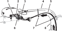
Assembling the Rear Wiring Harness to the Machine
Parts needed for this procedure:
| Rear wire harness | 1 |
| Cable tie | 3 |
Routing Wire Harness Along the Frame Tube
-
Locate the 165 cm (65 inch) branch and the 203 cm (80 inch) branch of the new electrical harness (Figure 83).
-
Route the 165 cm (65 inch) branch and the 203 cm (80 inch) branch of the new electrical harness between the valve mount for the 10 sprayer valves and right support for the manifold mount (Figure 84).
-
Route the 165 cm (65 inch) branch and the 203 cm (80 inch) branch of the electrical harness forward along the right frame tube (Figure 85).
-
Insert the push-in fasteners of the 203 cm (80 inch) branch of the rear wire harness into the holes in the right frame tube (Figure 85) where the push-in fasteners of the old rear harness where removed; refer to step 3 in Disconnecting the Front and Rear Wire Harnesses.
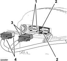
Connecting the Front and Rear Wire Harnesses
Note: Use a machine hoist when connecting the front and rear wire harnesses.
-
From under the machine along the right frame tube, locate the electrical connectors for the front and rear wire harnesses of the machine (Figure 86).
-
Connect the 10-socket connector of the front harness for the sprayer-harness interconnect into the 10-pin connector of the rear harness for the sprayer-harness interconnect (Figure 87).
-
Connect the 8-pin connector of the front harness for the sprayer-harness interconnect into the 8-socket connector of the rear harness for the rate switch (Figure 88).
-
Connect the 2-pin connector of the front harness for the rinse pump into the 2-socket connector of the rear harness for the rinse pump (Figure 89).
-
Connect the 2-pin connector of the front harness for the hose-reel power into the 2-socket connector of the rear harness for the hose-reel power (Figure 90).
-
Connect the 10-pin connector of the front harness for the sprayer-harness interconnect into the 10-socket connector of the rear harness for the sprayer-harness interconnect (Figure 91).
-
To ease connecting the navigation-electrical and data harnesses, ensure that the 1-socket connector of the rear-wire harness and the 4-socket connector of the rear-wire harness aligns to the top of the harness (Figure 92).
-
Secure the pump-interrupt relay of the rear-wire harness to the right support for the seat-support angle (Figure 93).
Routing the Pressure-Sense Tube for the Dash Gauge along the Rear Wire Harness
-
Route the pressure-sense tube for the dash gauge along the rear wire harness of the machine (Figure 94).
-
Secure the pressure-sense tube to the rear wire harness with 3 cable ties adjacent to the 3 push-in fasteners at the chassis anchor points for the rear wire harness (Figure 94).
Important: Do not pinch or collapse the pressure-sense tube; tighten the cable ties only enough to support the tube.
Installing the Engine-Control Module and Mounting Bracket (Machine Models with a Gasoline Engine)
-
Align the holes in the mounting bracket for the engine-control module with the hole in the support bracket of the engine and accessory case of the engine (Figure 95).
-
Assemble the mounting bracket to the engine with the 3 flange head bolts and 1 flange nut that you removed in step 1 of Removing the Engine-Control Module and Mounting Bracket (Machine Models with a Gasoline Engine); tighten the bolts and nuts by hand.
Installing the Undercarriage Shroud
-
Align the undercarriage shroud to the bottom chassis of the machine (Figure 96).
-
Slip the forward mounting flanges of the undercarriage shroud over the bolts and carriage bolt at the engine-mount brackets of the machine (Figure 96).
-
Assemble the undercarriage shroud to the engine-mount brackets and bolts (Figure 96) with the 4 flange locknuts (5/16 inch) that you removed in step 2 of Removing the Undercarriage Shroud.
-
Align the holes in the rear part of the undercarriage shroud with the holes in the chassis (Figure 97).
-
Assemble the rear part of the undercarriage shroud to the chassis (Figure 97) with the hardware that you removed in step 1 of Removing the Undercarriage Shroud as follows:
-
2016 machines—7 flange-head bolts (5/16 x 7/8 inch) and 7 washers (5/16 inch)
-
2017 and later machines—5 flange-head bolts (5/16 x 7/8 inch) and 5 washers (5/16 inch)
-
-
Torque the nuts and bolts to 1129 to 1582 N∙cm (100 to 140 in-lb).
Connecting the Rear Wire Harness
Parts needed for this procedure:
| Cable tie | 3 |
Routing the Wire Harness at the Manifold Mount
-
Route the 203 cm (80 inch) branch of the wire harness inboard of the support strut for the valve mount and rearward toward the 10-valve mount as shown in Figure 98.
-
Route the 81 cm (32 inch) wire-harness branch for the flow meter and agitation valve across the front of the manifold mount (Figure 98).
-
Insert the push-in fasteners of the 81 cm (32 inch) wire-harness branch into the holes in the lower flange of the manifold mount (Figure 98).
Routing the Wire Harness at the 10-Valve Mount
-
Route the 203 cm (80 inch) wire-harness branch across the back of the 10-valve mount with the 10 connectors for the nozzle valves rearward and below the valves (Figure 99).
-
Insert the push-in fasteners of the 203 cm (80 inch) wire-harness branch into the holes in the lower flange of the 10-valve mount (Figure 99).
Routing the Wire Harness for the Sprayer Pump
-
Route the 86 cm (34 inch) wire-harness branch for the spray-pump solenoid across the top of the sprayer frame channel and down toward the sprayer-pump solenoid (Figure 100).
-
Insert the push-in fastener of the 86 cm (34 inch) wire-harness branch into the hole in the sprayer frame channel (Figure 100).
Connecting the Wire Harness to the Manifold Mount Components
-
Route the connectors of the 203 cm (80 inch) wire-harness branch labeled Flow Meter and labeled Pressure Transducer rearward of the manifold mount (Figure 101).
-
Connect the 3-socket connector of the 203 cm (80 inch) wire-harness branch for the flow meter (not labeled) into the 3-pin connector of the harness of the flow meter (Figure 101).
-
Connect the 3-socket connector of the 203 cm (80 inch) wire-harness branch for the labeled Pressure Transducer into the 3-pin connector of the pressure transducer (Figure 101).
-
Adhere the magnet-harness anchors for the flow meter and the pressure transducer onto the surface of the manifold mount (Figure 101).
-
Route the 3-pin connector for the harness of the agitation valve forward of the manifold mount (Figure 102).
-
Connect the 3-pin connector for the harness of the agitation valve into the 3-socket connector of the 203 cm (80 inch) wire-harness branch labeled Agitation Valve (Figure 103).
Connecting the Wire Harness to the Solenoids for the Lift-Cylinder Manifold
-
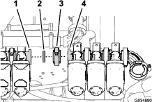
At the bottom of the lift-cylinder manifold, connect the 2-socket connector of the rear wire harness labeled Enable Solenoid into the 2-pin connector for the enable solenoid (Figure 104 and Figure 105).
-
At the lower right solenoid, connect the 2-socket connector of the rear wire harness labeled Right Down into the 2-pin connector for the right down solenoid (Figure 104 and Figure 105).
-
At the upper right solenoid, connect the 2-socket connector of the rear wire harness labeled Right Up into the 2-pin connector for the right up solenoid (Figure 104 and Figure 105).
-
At the lower left solenoid, connect the 2-socket connector of the rear wire harness labeled Left Down into the 2-pin connector for the left down solenoid (Figure 104 and Figure 105).
-
At the upper left solenoid, connect the 2-socket connector of the rear wire harness labeled Left Up into the 2-pin connector for the left up solenoid.
Connecting the Wire Harness to the Sprayer Valves
-
Route the 3-socket connectors of the 203 cm (80 inch) wire-harness branch with labels Nozzle Valve 1 through Nozzle Valve 5 rearward of the 10-valve mount and below nozzle valves 1 through 5 (Figure 106).
-
Route the 3-socket connectors of the 203 cm (80 inch) wire-harness branch with labels Nozzle Valve 6 through Nozzle Valve 10 rearward of the 10-valve mount and below nozzle-valves 6 through 10 (Figure 106).
-
Connect the 3-pin socket connector of the rear wire harness labeled Nozzle 1 to the 3-pin connector of the harness for nozzle-valve 1 (Figure 106).
Important: It is important that you connect each labeled 3-pin socket connector of the rear wire harness to the correct 3-pin connector at each nozzle-valve position.
-
Repeat step 3 at the nozzle-valve positions 2 through 10 (Figure 106).
Connecting the Wire Harness to the Sprayer Pump and the Speed Sensor
-
At the back of the machine—inboard of the sprayer pump, connect the 2-socket connector labeled Spray Pump Solenoid of the 86 cm (34 inch) wire-harness branch into the 2-pin connector of the relay for the pump (Figure 107).
-
At back of the machine (between the right frame tube and the right fender) connect the 3-pin connector of the speed-sensor harness at the right hydraulic-traction motor from the 3-socket connector (unmarked) of the rear, main harness (Figure 108).
Routing the Wire Harness through the Engine Compartment
-
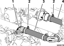
Route the 165 cm (65 inch) branch of the wire harness up and into the rear part of the engine compartment, along the right support for the engine shroud—forward of the duct that connects the air filter and the engine (Figure 109).
Note: You will secure the 165 cm (65 inch) branch of the rear wire harness in Routing the Navigation-Data and Electrical Harness to the Battery.
-
Route the 165 cm (65 inch) branch of the wire harness across the seat-box angle and down along the left support for the engine shroud (Figure 110).
Note: You will secure the 165 cm (65 inch) branch of the rear wire harness in Routing the Navigation-Data and Electrical Harness to the Battery.
-
Route the 165 cm (65 inch) branch of the wire harness down along the left support for the engine shroud and under the left frame tube (Figure 111).
Note: You will secure the 165 cm (65 inch) branch of the rear wire harness in Routing the Navigation-Data and Electrical Harness to the Battery.
-
Route the 50 A fuse and the positive- and negative-ring terminals of the 165 cm (65 inch) branch of the wire harness to the top of the battery (Figure 111).
Note: You will complete the installation of the ring terminals in Assembling the Rear GeoLink Harness, Navigation-Data and Electrical Harness, and Modem Power Harness to the Battery Cables.
Routing the Wire Harness for the Sprayer Pump Shutoff Circuit
-
Rotate the driver’s seat forward and place the prop rod for the seat into the detent in the console channel.
-
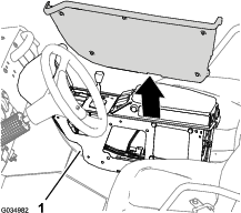
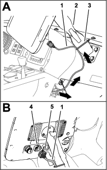
Remove the 5 flange-head bolts (1/4 x 3/4 inch) that secure the cover at the left side of the center console (Figure 112).
-
Remove the cover from the center console (Figure 113).
Note: If needed, rotate the driver’s seat down when removing the cover from the center console.
-
Route the 81 cm (32 inch) branch of the rear-wire harness along the front wire harness and up through the grommet in the console channel (Figure 114).
-
Route the 81 cm (32 inch) branch of the rear-wire harness forward along the front wire harness and through the grommet in the back of the center console (Figure 114).
Adding the Sprayer Pump Shutoff Circuit to the Sprayer-Pump Switch
-
Press in the latch for the 8-socket connector at the sprayer-pump switch, and separate the connector from the switch (Figure 115).
-
Position the 8-socket connector so that you can see the back of the connector and the latch is up (Figure 116).
-
Insert the terminal at the end of the 81 cm (32 inch) branch of the rear-wire-harness into terminal position #4 of the 8-socket connector (Figure 116).
Note: Ensure that the latch of the terminal snaps securely into the 8-socket connector.
-
Connect the 8-socket connector if the wire harness with the 8-pin connector if the sprayer-pump switch (Figure 117).
-
Secure the 81 cm (32 inch) branch of the rear-wire-harness to the front wire harness of the machine as shown in Figure 117.
-
Align the cover that you removed in step 3 of Routing the Wire Harness for the Sprayer Pump Shutoff Circuit to the left side of the center console (Figure 119).
-
Assemble the cover to the center console with the 5 flange-head bolts (1/4 x 3/4 inch) that you removed in step 2 of Routing the Wire Harness for the Sprayer Pump Shutoff Circuit, and torque the bolts to 520 to 678 N∙cm (46 to 60 in-lb).
Connecting the Pressure-Sense Tube for the Dash Gauge
Connecting the Pressure-Sense Tube for the Dash Gauge—Machines Without an Optional Hose Reel Kit
Connecting the Pressure Sense-Tube—Optional Spray Gun Kit or Optional Pivoting Hose Reel Kit
Installing the Navigation Receiver
Parts needed for this procedure:
| Receiver mount | 1 |
| U-bolt | 2 |
| Flange locknut (3/8 inch) | 4 |
| Modem antenna bracket | 1 |
| Hex-head bolt (5 x 16 mm) | 3 |
| Washer (5 mm) | 3 |
| Navigation receiver—GeoLink precision spray system kit (Model 41633 or Model 41634) | 1 |
Assembling the Navigation Receiver Bracket to the Machine
-
Align the slot that is in the center of the receiver mount with the weld seam at the centerline of the ROPS tube (Figure 123).
Note: Ensure that the larger flange with 2 holes is rearward of the ROPS tube and the smaller flange with 1 hole is forward.
-
Assemble the receiver mount to the ROPS tube (Figure 124) with the 2 U-bolts and 4 flange locknuts (3/8 inch).
-
Torque the nuts to 37 to 45 N∙m (27 to 33 ft-lb).
-
Assemble the navigation receiver to the mount as follows:
Assembling the Navigation Receiver to the Machine
-
Align the 3 threaded in the base of the navigation receiver to the 3 holes in the receiver mount (Figure 125).
-
Align the hole and slot in the modem-antenna bracket with the holes in the receiver mount (Figure 125).
-
Assemble the navigation receiver and antenna bracket to the mount (Figure 125) with the 3 hex-head bolt (5 x 16 mm) and 3 washers (5 mm).
-
Torque the 3 bolts to 576 to 712 N∙cm (51 to 63 in-lb).
Installing the Modem Antenna to the Machine
Parts needed for this procedure:
| Modem antenna—GeoLink precision spray system kit (Model 41633 or Model 41634) | 1 |
| Cable ties—GeoLink precision spray system kit (Model 41633 or Model 41634) | 7 |
Installing the Modem Antenna to the Navigation Receiver Mount
-
Clean any grease of oil from the surface of the modem-antenna bracket.
-
Remove the backing from the double sided adhesive liner at the bottom of the modem antenna (Figure 126).
-
Adhere the modem antenna to the top of the modem-antenna bracket as shown in Figure 126.
-
Secure the antenna bracket with 3 cable ties as shown in Figure 127.
-
Secure the wire harness of the modem antenna to the bracket as shown in Figure 127.
Routing the Modem-Antenna Harness
-
Route the modem-antenna harness to the right, along the roll bar (Figure 128).
-
Route the harness down, and forward as shown in Figure 128.
-
You will secure the modem-antenna harness to the roll bar in Routing and Connecting the Data Cable to the Navigation Receiver.
Installing the Monitor Visor
Parts needed for this procedure:
| X25 Sprayer Monitor—GeoLink precision spray system kit (Model 41633 or Model 41634) | 1 |
| Adhesive strips | 2 |
| Threaded standoff | 1 |
| Display hood | 1 |
Applying the Adhesive Strips to the Sprayer Monitor
-
Clean the top surface of the X25 sprayer display with rubbing alcohol and a clean rag.
-
Remove the backing from the 2 adhesive strips.
-
At the top of the sprayer monitor, align the strips to the sprayer monitor as shown in Figure 129.
-
Firmly press the adhesive strips to the top of the monitor.
Assembling the Display Hood to the Sprayer Monitor
-
At the back of the sprayer monitor and with the 2 connectors (26 pin) aligned down, remove the top locknut (5 mm) from the stud for the ball-pivot fitting (A of Figure 130).
-
Apply a coat of thread-locking compound (wicking—medium-high strength) to the threads for the nut portion of the threaded standoff (Figure 131).
-
Thread the standoff into the stud for the ball-pivot fitting (B of Figure 130) and torque the standoff to 250 N∙cm (22 in-lb).
-
Apply a coat of thread-locking compound (wicking—medium-high strength) to the threads for the stud portion of the threaded standoff (Figure 131).
-
Remove the backing from the 2 adhesive strips that you applied in Applying the Adhesive Strips to the Sprayer Monitor.
-
Align the hole in the display hood with the stud portion of the threaded standoff (B of Figure 130).
-
Assemble the hood to the monitor (C of Figure 130) with the locknut (5 mm) that you removed in step 1.
Note: Press down on the areas of the top of the hood with the adhesive strips underneath.
-
Torque the nut to 250 N∙cm (22 in-lb).
Installing the Sprayer Monitor
Parts needed for this procedure:
| Ball mount—GeoLink precision spray system kit (Model 41633 or Model 41634) | 1 |
| Monitor arm—GeoLink precision spray system kit (Model 41633 or Model 41634) | 1 |
| Stiffener bracket | 1 |
| Flange-head bolt (1/4 x 1-1/2 inches) | 4 |
| Washer (1/4 inch) | 4 |
| Flange locknut (1/4 inch) | 4 |
Preparing the Dash Panel
Removing the Hood Bracket
Preparing the Stiffener Bracket
Assemble the clip nuts that you removed in Removing the Hood Bracket onto the stiffener bracket as shown in Figure 134.
Installing the Ball-Pivot Mount
-
Assemble the ball-pivot mount to the dash with the 4 flange-head bolts (1/4 x 1-1/2 inch), stiffener plate, and flange locknut (1/4 inch) as shown in Figure 135.
-
Loosely assemble the stiffener plate to the 4 flange-head bolts (1/4 x 1-1/2 inch) with 4 locknuts (1/4 inch) as shown in Figure 136.
-
Loosely assemble stiffener plate with the 2 Phillips panhead screw (1/4 x 1 inch) and flange locknut (1/4 inch) that you removed in Removing the Hood Bracket.
-
Torque the flange-head bolts, Phillips panhead screws, and flange locknut to 1,163 to 1,435 N∙cm (103 to 127 in-lb)
Mounting the Sprayer Monitor to the Dash
-
Loosen the knob of the monitor arm until you can slip both the ball pivot for the fitting at the back of the sprayer monitor and the ball pivot for the mount at the dash panel into the socket monitor arm (Figure 137).
-
From the driver’s seat (left seat), adjust to position of the sprayer monitor so that you can easily view the display screen (Figure 137).
-
Tighten the knob for the monitor arm by hand (Figure 137).
Installing the Wire Harnesses for the Navigation Components
Parts needed for this procedure:
| Data and electrical harness—GeoLink precision spray system kit (Model 41633 or Model 41634) | 1 |
| Cable tie—GeoLink precision spray system kit (Model 41633 or Model 41634) | 8 |
Identifying the Navigation-Data and Electrical Harness
Routing and Connecting the Data Cable to the Navigation Receiver
-
Route the 302 cm (119 inches) branch of the data-harness into the right side of the engine compartment (adjacent to the air filter for the engine) and rearward under the bottom right area of the rear engine shroud (Figure 139).
-
Route the 302 cm (119 inches) branch of the data harness along the right ROPS tube with the 12-socket connector (gray) and 12-socket connector (black) up toward the navigation receiver (Figure 140).
-
Align the 2 keys at the long face of the 12-socket connector of the data harness labeled with the 2 key slots in the bottom, horizontal wall of the left (gray) 12-pin connector of the navigation receiver (Figure 141).
Note: Use caution when connecting wire harness to the navigation receiver; the alignment keys of the harness connectors are unique to the keyways of the pin connectors of the navigation receiver.
-
Plug the connector of the data harness into the left (gray) 12-pin connector of the navigation receiver until the connector locks snap together securely (Figure 141).
-
Align the 2 keys at the short side of the 12-socket connector—data harness labeled with the 2 key slots in the left, vertical wall of the right (black) 12-pin connector of the navigation receiver (Figure 141).
Note: Use caution when connecting wire harness to the navigation receiver; the alignment keys of the harness connectors are unique to the keyways of the pin connectors of the navigation receiver.
-
Plug the connector of the data harness into the right (black) 12-pin connector of the navigation receiver until the connector locks snap together securely (Figure 141).
-
Secure the 302 cm (119 inches) branch of the data harness to the right ROPS tube with cable ties as shown in Figure 140.
Note: Ensure that the cable is slack between the 12-socket connectors and the cable tie.
Connecting the Navigation-Data and Electrical Harness to the Rear GeoLink Harness
-
Route the 302 cm (119 inches) data-harness branch of the electrical harness (Figure 142) with the 4-pin connector labeled down to the area where the front and rear wire harness for the machine connect; refer to Figure 92 in Connecting the Front and Rear Wire Harnesses.
-
Route the 34 cm (13-1/2 inches) data-harness branch (Figure 142) with the 4-pin connector labeled down to the area where the front and rear wire harness for the machine connect; refer to Figure 92 in Connecting the Front and Rear Wire Harnesses.
-
Connect the 4-pin connector of the data-harness branch labeled into the 4-socket connector of the rear GeoLink harness for the CAN 2 / sprayer-controller circuit (Figure 143).
Removing the Terminating Resistor
Remove the terminating resistor from the 6-socket connector of the data cable as shown in Figure 144.
Note: You no longer need the terminating resistor.
Routing the Navigation-Data and Electrical Harness to the Battery
-
Route the 270.5 cm (106-1/2 inch) power branch of the navigation-data and electrical harness across the seat-box angle and down along the left support for the engine shroud (Figure 145).
-
Secure the harness to the engine-shroud support with cable ties (Figure 145).
-
Route the 270.5 cm (106-1/2 inch) power branch along the left support for the engine shroud and under the left frame tube (Figure 146).
-
Secure the harness to the hole in the seat-box angle and the engine-shroud support with 3 cable ties (Figure 146 and Figure 147).
-
Route the 10 A fuse and the positive- and negative-ring terminals of the 220 cm (86-5/8 inch) branch of the electrical-harness for the navigation system to the top of the battery (Figure 147).
Note: You will complete the installation of the ring terminals in Assembling the Rear GeoLink Harness, Navigation-Data and Electrical Harness, and Modem Power Harness to the Battery Cables.
Routing and Connecting the Data Cable to the Sprayer Monitor
-
At the right side of the engine compartment, route the 226 cm (89 inches) data-harness branch for the sprayer monitor forward of the air filter for the engine and down toward the lower right corner of the radiator (Figure 148).
-
Route the route the 226 cm (89 inches) data-harness branch forward and through the 2 R-clamps at the bottom of the machine (Figure 148).
-
Route the route the 226 cm (89 inches) data-harness branch forward and up through grommet that surrounds the hole in the floor panel (Figure 149).
-
Secure the 226 cm (89 inches) data-harness branch to the front wire harness of the machine with 3 cable ties.
-
Route the route the 226 cm (89 inches) data-harness branch up and along the front wire harness of the machine (Figure 149).
-
Route the route the 226 cm (89 inches) data-harness branch up through grommet that surrounds the hole in the dash panel (Figure 150).
-
Align the 26-socket connector of the data harness branch with the 26-pin connector of the sprayer monitor and press the socket connector into the pin connector until the connector latches securely (Figure 150).
-
Secure the 226 cm (89 inches) data-harness branch to the monitor arm with a cable tie (Figure 150).
Assembling the Modem Power Harness to the Machine
Parts needed for this procedure:
| Modem power harness—1850 mm (72-7/8 inches)—GeoLink precision spray system kit (Model 41633 or Model 41634) | 1 |
| Cable ties—GeoLink precision spray system kit (Model 41633 or Model 41634) | 5 |
Routing the Modem Power Harness
-
Between the fuel tank bracket and the right, front fender, route the tab terminal (labeled ) and 2 ring terminal (labeled and ) of the modem power harness under the frame of the machine (Figure 151).
-
At the inboard side of the right seat box, route the modem power harness forward and power harness connector labeled RS232 along the machine wire harness (Figure 152).
Note: The connector labeled RS232 is not used.
-
Route the modem power harness across the top of the radiator, along the machine wire harness (Figure 153).
Connecting the Wire Harness to the Fuse Block
-
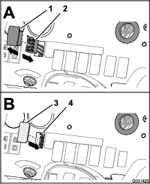
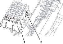
Plug the terminal of the modem power harness labeled into the socket connector for options power of the fuse block (Figure 154).
Note: If fuse block of your machine does not have an available options-power circuit, install an additional options-fuse block; refer to your authorized Toro distributor.
-
Insert the fuse (10 A) into the fuse-block socket (Figure 155) for the options power circuit that you used in step 1.
-
Secure the switched power and ground branch of the kit wire harness to the machine wire harness with 5 cable ties.
Routing the Harness to the Battery
-
Route the ring terminals of the harness labeled and rearward, and over the seat support (Figure 156).
-
Route the ring terminals under the left frame tube and across the top of the battery (Figure 156).
Note: You will assemble the ring terminals to the battery cables in Assembling the Rear GeoLink Harness, Navigation-Data and Electrical Harness, and Modem Power Harness to the Battery Cables.
Assembling the Modem Data Harness to the Machine
Parts needed for this procedure:
| Modem data harness—300 cm (118 inches)—GeoLink precision spray system kit (Model 41633 or Model 41634) | 1 |
| Cable ties—GeoLink precision spray system kit (Model 41633 or Model 41634) | 8 |
Connecting the Modem Data Harness to the Sprayer Display
-
Align the modem data harness with the RS-232 connector labeled toward the sprayer monitor (Figure 157).
-
At the front of the sprayer display, remove the cap from the RJ45 port (Figure 158).
-
Plug the RJ45 connector of the modem data cable labeled X-CONSOLE into the RJ45 port of the sprayer display (Figure 158).
-
Assemble the port seal nut over the RJ45 port of the sprayer display, and tighten the seal nut (Figure 158).
-
Assemble compression nut over port seal nut, and tighten the compression nut (Figure 158).
Routing the Modem Data Cable
-
Route the modem data cable through the storage compartment (Figure 159).
-
Route the modem data cable along the wire harness of the machine, and through the grommet in the floor plate (Figure 160).
-
Secure the modem data cable to the machine wire harnesses with 4 cable ties.
-
At the bottom of the machine, route the modem data cable rearward, along the wire harness of the machine (Figure 161).
-
At the rear side of the radiator, route the modem data cable upward (Figure 162).

-
Secure the modem data cable to the machine wire harnesses with 4 cable ties.
-
Route the modem data cable along the modem power harness (Figure 163), out the right side of the machine, and between the fuel tank bracket and the right, front fender.
Installing the CL-55 Modem
Parts needed for this procedure:
| CL-55 modem—GeoLink precision spray system kit (Model 41633 or Model 41634) | 1 |
| Modem bracket | 1 |
Connecting the Antenna Harness to the Modem
-
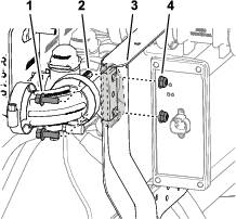
Plug the coaxial connector of the modem-antenna harness labeled into the coaxial port of the CL-55 modem marked WIFI/BT, and tighten the coaxial connector (Figure 164).
-
Plug the blue coaxial push-in connector of the modem-antenna harness labeled into the connector of the CL-55 modem marked , until the connectors latch securely (Figure 164).
-
Plug the violet coaxial push-in connector of the modem-antenna harness labeled into the connector of the CL-55 modem marked , until the connectors latch securely (Figure 164).
-
CDMA Modems Only: Plug the red coaxial push-in connector of the modem-antenna harness labeled LTE-2 into the connector of the CL-55 modem marked 4G DIV, until the connectors latch securely (Figure 164).
Note: The GSM modem does not have an LTE-2 connector.
Connecting the Modem Data and Power Harnesses to the Modem
-
Plug the 4-pin connector of the modem data harness labeled into the 4-socket connector (unmarked) of the CL-55 modem, and tighten the knurled nut of the 4-pin connector (Figure 165).
-
Plug the 18-socket connector of the modem power harness labeled into the 18-pin connector of the CL-55 modem (Figure 165).
Installing the Modem to the Machine
Align the modem bracket to the right seat-box panel over the bolt heads and secure it with the magnets (Figure 166).
Important: Ensure that the wire harnesses are routed within the modem bracket.
Routing the ISO-CAN Bus Harness
Parts needed for this procedure:
| ISO-CAN bus harness—302 cm (119 inches—GeoLink precision spray system kit Model 41633 or Model 41634) | 1 |
| Cable ties—GeoLink precision spray system kit (Model 41633 or Model 41634) | 12 |
Connecting the ISO-CAN Bus Harness to the GeoLink Harness
-
At the front of the machine, align the 4-pin connector of the ISO-CAN bus harness—302 cm (119 inches) labeled TO ISOBUS toward the dash panel (Figure 167).
-
Remove the ISO bus terminator from the 4-socket connector of the GeoLink harness labeled CAN 1 ISOBUS TERMINATOR (Figure 168).
Note: You no longer need the cap.
-
Plug the TO ISOBUS connector of the ISO-CAN bus harness into the CAN 1 ISOBUS TERMINATOR connector of the GeoLink harness (Figure 168).
Routing the Harness to the Console Base
-
Route the other end of the ISO-CAN bus harness through the grommet of the floor (Figure 169).
-
Secure the ISO-CAN bus harness to the machine wire harness with 2 cable ties.
-
At the bottom of the machine, route the ISO-CAN bus harness along the wire harness of the machine (Figure 170).
-
Secure the ISO-CAN bus harness to the machine wire harness with 3 cable ties.
-
Rotate the passenger seat forward and support it with the prop rod.
-
At the right side of the radiator, rout the ISO-CAN bus harness up, along the machine wire harness, and toward the center console (Figure 171).
-
Route the ISO-CAN bus harness under the console base and along the machine wire harness (Figure 172).
-
Route the 3-pin connector (labeled TO TORO CANBUS) and 3-socket connector (labeled CAN PORT A) of the ISO-CAN bus harness through the hole in the console base (Figure 172).
-
Secure the ISO-CAN bus harness to the machine wire harness with 6 cable ties.
Connecting the ISO-CAN Bus Harness to the Machine Wire Harness
-
Remove the cap from the 3-socket connector of the machine wire harness (labeled CAN DIAGNOSTICS INTERCONNECT), as shown in Figure 173.
-
Plug the 3-pin connector of the ISO-CAN bus harness (labeled TO TORO CANBUS) into the 3-socket connector of the machine wire harness (labeled CAN DIAGNOSTICS INTERCONNECT), as shown in Figure 173.
Removing the CAN Bus Resistor
Removing the Console Side Panel
Removing the Terminating Resistor
Forward of the TEC Controller, remove the resistor 75Ω from the 3-socket connector (not labeled) of the machine wire harness (Figure 175).
Note: Retain the resistor for installation in Installing the Adapter Harness and Terminating Resistor.
Note: You will install the side panel to the center console when you install the AutoSteer Kit for the Multi Pro 5800 Turf Sprayer with GeoLink; refer to the setup instructions in the AutoSteer kit Installation Instructions.
Installing the Adapter Harness and Terminating Resistor
Parts needed for this procedure:
| Adapter harness—13 cm (5 inches) | 1 |
| Cable tie | 1 |
-
At the satellite receiver, remove the ISO bus terminator for the 6-socket connector of the GeoLink harness (Figure 177).
Note: You no longer need the ISO bus terminator.
-
Plug the 6-pin connector of the adapter harness—13 cm (5 inches) into the 6-socket connector of the GeoLink harness (Figure 177).
-
Plug the resistor that you removed in Removing the Terminating Resistor into the 3-socket connector of the adapter harness (Figure 178).
-
Secure the adapter harness to the GeoLink harness with a cable tie.
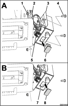
Connecting the Wire Harness for the Optional Pivoting Hose-Reel Kit
-
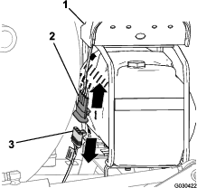
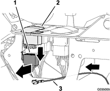
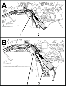
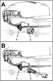
At the back of the machine, locate the wire harness for the electric hose-reel kit at the back of the sprayer tank (A of Figure 179).
-
Remove the plug from the 2 pin connector of the rear, main harness for the hose-reel power (B in Figure 179).
-
Connect the 2 socket connector of the harness for the electric-hose reel into the 2 pin connector of the rear, main harness (C in Figure 179).
-
Remove the cap from the 3-socket connector of the rear, main harness for the spray harness interconnect (B in Figure 179).
-
Connect the 3 pin connector of the harness for the electric-hose reel into the 3 pin socket of the rear, main harness (C in Figure 179).
Connecting the Compressor Wire Harness for the Optional Foam-Marker Kit
-
At the end of the 236 cm (93 inch) branch of the wire harness, align the 4-socket connector of the wire harness for the finishing kit with the 4-pin connector of the wire harness from the compressor (Figure 180).
-
Insert the 4-pin connector into the 4-socket connector (Figure 180).
Note: Press the connectors together until the latch snaps securely.
Connecting the Optional Tank-Rinse Kit
-
Connect the 6-pin connector of the rinse-pump harness from the 6-socket connector of the rear, main harness (Figure 181).
-
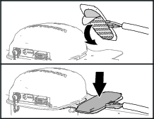
Align the rinse-pump cover over the saddle plate for the rinse pump (Figure 182).
-
Press together the sides of the rinse-pump cover and align the tabs of the cover with the saddle plate (Figure 182).
-
Insert the tabs into the slots and release the sides of the cover (Figure 182).
Completing the Installation of the GeoLink Spray System-Finishing Kit
Closing the Seats
Move the prop rods for the seats into the slots and tilt the seats down.
Assembling the Rear GeoLink Harness, Navigation-Data and Electrical Harness, and Modem Power Harness to the Battery Cables
-
Route the positive terminal (red wire), negative terminal (black wire), and fuses block (50 A) of the rear wire harness up between the battery box and the chassis of the machine (Figure 183).
-
Route the positive terminal (red wire), negative terminal (black wire), and 10 A fuse block of the navigation-electrical harness up between the battery box and the chassis of the machine.
-
Route the ring terminals labeled and of the modem power harness up between the battery box and the chassis of the machine.
-
Remove the T-bolts and hex nuts from the terminals of the positive and negative battery cables (Figure 183).
-
Assemble a T-bolt through the positive terminal (red wire) of the rear wire harness, the positive terminal of the navigation-electrical harness, modem power harness, and terminal of the positive battery cable (Figure 183).
-
Loosely secure the terminals and the T-bolt with a hex nut (Figure 183).
-
Assemble a T-bolt through the negative terminal (black wire) of the rear wire harness, the negative terminal of the navigation-electrical harness, modem power harness, and terminal of the negative battery cable (Figure 183).
-
Loosely secure the terminals and the T-bolt with a hex nut (Figure 183).
Connecting the Battery
-
Connect the positive (red) cable to the positive (+) battery post, and tighten the nut; refer to Figure 183 in Assembling the Rear GeoLink Harness, Navigation-Data and Electrical Harness, and Modem Power Harness to the Battery Cables.
-
Connect the negative (black) cable to the negative (–) battery post, and tighten the nut; refer to Figure 183 in Assembling the Rear GeoLink Harness, Navigation-Data and Electrical Harness, and Modem Power Harness to the Battery Cables.
-
Slide the insulator boots over both battery posts.
-
Install the battery cover and secure it with the strap; refer to Figure 1 in Disconnecting the Battery.
Programming the Machine Settings
-
Insert the key into the key switch and rotate the switch to the ON position.
Note: Do not start the engine.
-
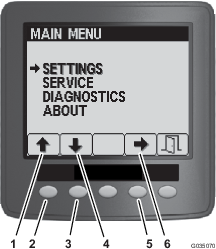
At the splash screen, press and hold the button 5 (far right) on the InfoCenter to access the Main Menu screen (Figure 184).


-
On the Main Menu, press button 1 or button 2 until the Settings option is highlighted, and press button 4 to navigate to the Settings menus (Figure 185).
-
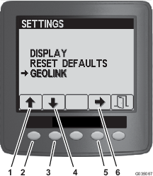
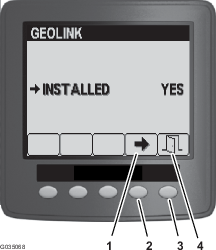
On the Settings menu, press button 1 or button 2 until the GeoLink option is highlighted, and press button 4 to navigate to the GeoLink menu (Figure 186).
-
On the GeoLink menu. press button press button 4 to select the Yes option, and press the button 5 to save your settings and exit the menu (Figure 187).
-
Rotate the key switch to the OFF position (Figure 188).

-
Rotate the key switch to the ON position (Figure 188).
Note: The splash screen for the GeoLink system should display in the InfoCenter.

-
Rotate the key switch to the OFF position.
Powering the GeoLink Components
-
Turn the ignition key to the RUN (gasoline) or PREHEAT/RUN (diesel) position.
-
Verify that the following components indicate that each receives power:
-
Turn the ignition key to the OFF position.
-
Verify that power is shut off at the following components:
-
Control console
-
Satellite receiver
-
Automatic section controller
-

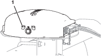
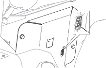
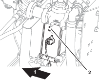
Verifying the Software Version
-
Turn the ignition key to the RUN(gasoline) or PREHEAT/RUN (diesel) position.
-
Press the ABOUT (Toro) icon at the upper left corner of the control console (Figure 194).

-
Compare the software version numbers at the following locations:
-
When used, the cover page of the Software Guide for your GeoLink system
-
Displayed in the command console
Note: If the software versions differ, contact Toro NSN at 1-844-GEOLINK (1-844-436-5465) or NSNTech@toro.com for customer service.
-
Selecting the Units of Measure
Select the units of measure; refer to the Operator’s Manual or Software Guide for your GeoLink system.
Creating a Field
Create a new field; refer to the Operator’s Manual or Software Guide for your GeoLink system.
Creating a New Product and Application Rate
Create a new product and application rate entry; refer to the Operator’s Manual or Software Guide for your GeoLink system.
Creating a Spray Job
-
Press the Job Menu and press the CREATE NEW JOB icon (Figure 195).
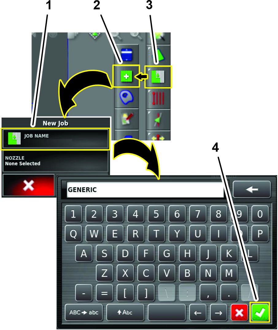
-
Use on-screen keyboard to type a name for the generic job, and press the confirm icon (Figure 195).
-
In the new job dialog box, press the NOZZLE icon (Figure 196).
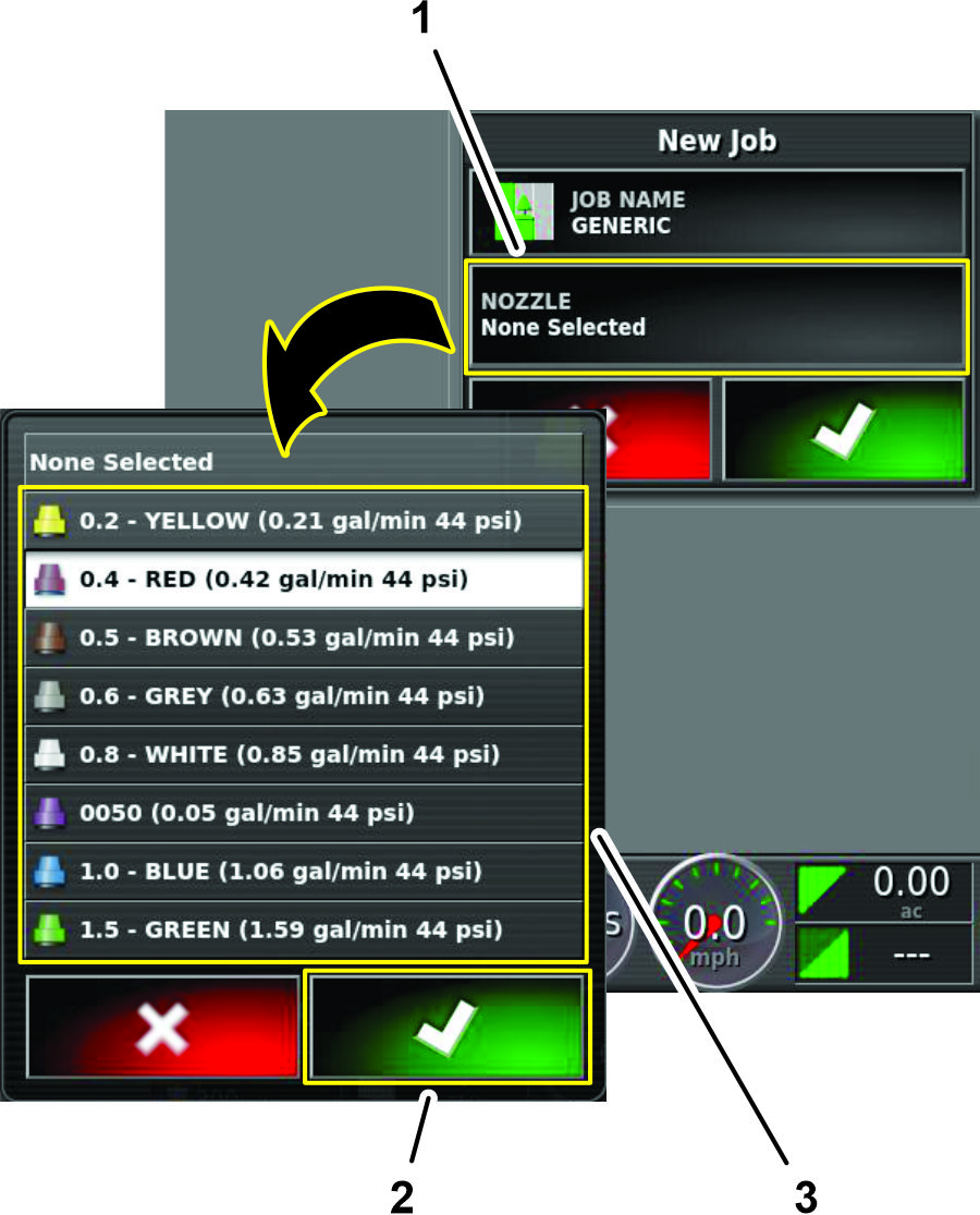
-
In the nozzle selection list, press any nozzle icon, and press the confirm icon (Figure 196).
-
In the new job dialog box, press the confirm icon (Figure 197).
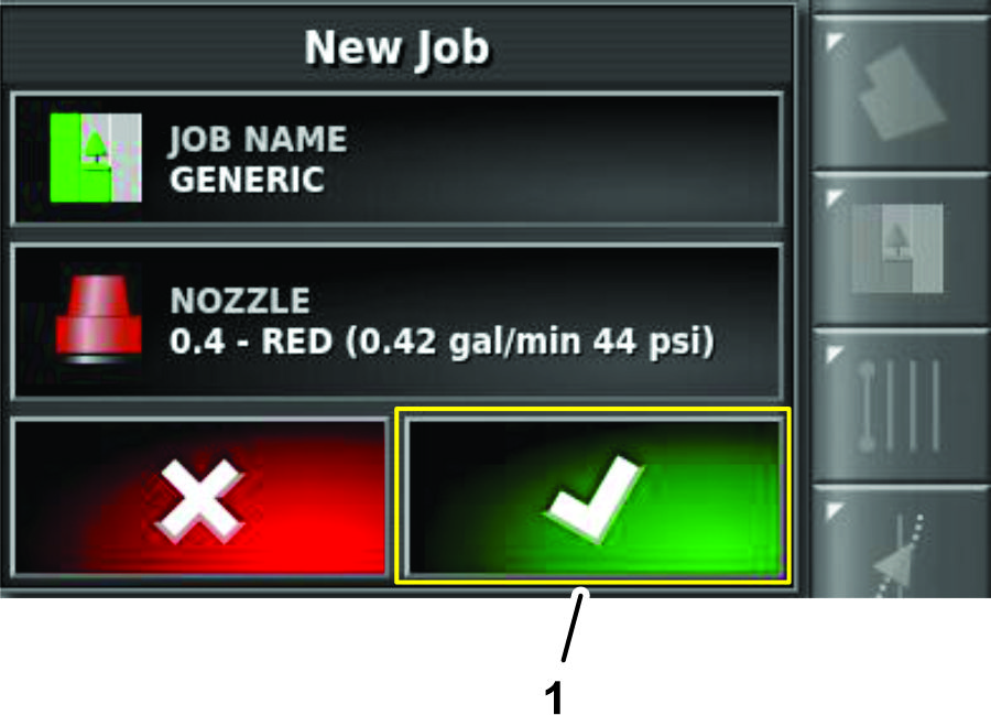
Checking the Spray System
-
Engage the parking brake.
-
Add 200 L (50 US gallon) of water into the spray tank; refer to the Operator’s Manual for your machine.
-
Start the engine and set the engine speed to fast.
-
On the GeoLink control console, press the SPRAY RATE CONTROLLER icon (Figure 198).
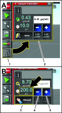
-
In the spray rate controller dialog box, press the RATE CONTROL MODE icon until manual mode displays (Figure 198).
-
Use the decrement icon (-) or increment icon (+) to adjust the spray system pressure (Figure 198) to 13.75 bar (200 psi).
-
On the machine, press the master-section switch to the ON position (Figure 199).
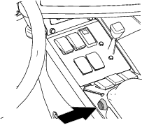
-
On the GeoLink control console, press the MASTER SWITCH icon (Figure 200) to the ON (green).
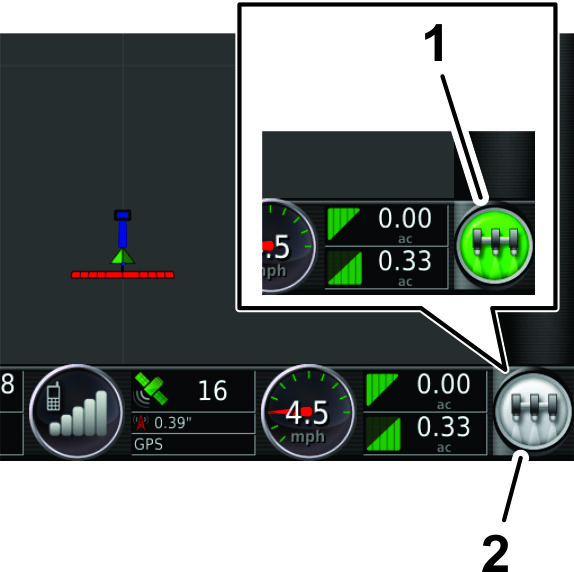
-
Check all sprayer fittings and components for leaks.
Note: If you find any leaks, shut off the engine and repair the fitting or component.
Balancing the Agitation Bypass Valve
Checking System and Agitation Bypass Pressure
-
Engage the parking brake, and start the engine.
Note: Allow the engine and hydraulic system to warm for 10 minutes.
-
Ensure that the master section switch to the OFF position.
-
Set the spray-pump switch and the tank agitation switch to the ON position.
-
Set the left, center, and right section switches to the ON position.
-
Set the engine speed to fast.
-
On the GeoLink control console, press the SPRAY RATE CONTROLLER icon.
-
In the spray rate controller dialog box, press the RATE CONTROL MODE icon until manual mode displays (Figure 201).
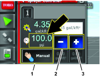
-
Press the decrement icon (-) or increment icon (+) to adjust the spray system pressure (Figure 201) to 6.9 bar (100 psi).
-
On the machine, set the tank agitation switch to the OFF position.
-
Observe the spray system pressure. If the spray system pressure is 6.9 bar (100 psi), the agitation valve is correctly adjusted.
If the spray system pressure changed, adjust the agitation bypass valve; refer to Adjusting the Agitation Bypass Valve.
Adjusting the Agitation Bypass Valve
-
With the tank agitation switch in the OFF position, walk to the back of the machine and locate the agitation bypass valve.
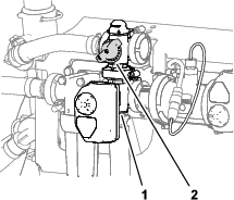
-
Adjust the agitation-bypass valve (Figure 202) until the gauge indicates 689 kPa (100 psi) sprayer system pressure.
-
Set the tank agitation switch to the ON position and observe the spray system pressure.
Note: If the spray system-pressure gauge indicates greater than or less than 6.9 bar (100 psi), repeat steps 1 and 2.
-
Set the tank agitation switch to the OFF position and observe the spray system pressure.
Note: If the spray system-pressure gauge indicates greater than or less than 6.9 bar (100 psi), repeat steps 1 and 2.
Calibrating the Flow Meter
Calibrate the flow meter; refer to the Operator’s Manual or Software Guide for your GeoLink system.
Verifying the Cellular Status
-
Press the SYSTEM INFORMATION icon, and then swipe the FULL SCREEN icon in the upper right corner of the system information window (Figure 203).
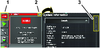
-
In the system information screen, use the scroll bar to navigate to the CL55 icon (Figure 204).
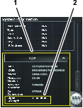
-
Press the CL55 icon to display the signal strength information.(Figure 204), and verify that the modem signal strength is between -60 dBm and -99 dBm.
Note: If the modem signal is equal to or less than -100 dBm, contact your authorized Toro distributor, Toro NSN at 1-844-GEOLINK (1-844-436-5465), or NSNTech@toro.com for customer service.
-
Swipe the FULL SCREEN icon to minimize the system information screen.
Calibrating the Compass
Perform a compass calibration at the distributor’s location; refer to Calibrating the Compass in the Operator’s Manual or Software Guide for your GeoLink system.
Clearing NVRAM
Changing the Setup Screen for Dealer Access
Important: You must erase the nonvolatile RAM at the customer location.
-
Contact Toro NSN at 1-844-GEOLINK (1-844-436-5465) or NSNTech@toro.com for customer service to request the dealer access level password.
-
Rotate the ignition key to the ON position.
-
Press the SETUP icon on the main screen (Figure 205).
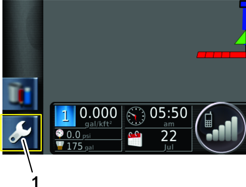
-
In the setup screen, press the USER icon and the ACCESS LEVEL icon(Figure 206).
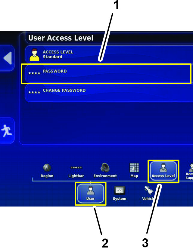
-
Press the PASSWORD icon (Figure 206).
-
Use the on-screen keyboard to enter the password that you received in step 1, and press the confirm icon (Figure 207).
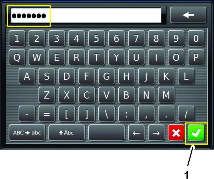
Note: The user access level screen displays the DEALER icon (Figure 208).

Erasing the Nonvolatile RAM
-
In the setup screen, press the SYSTEM icon, GPS icon, and ADVANCED CONFIGURATION icon (Figure 209).
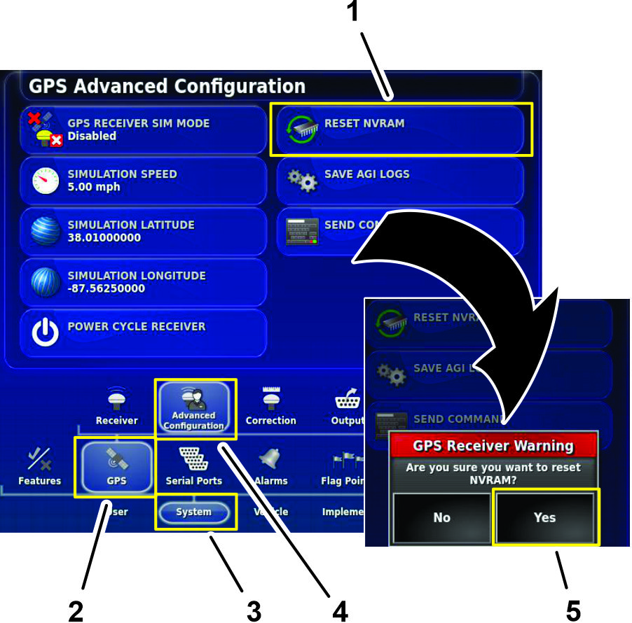
-
In the GPS Advanced Configuration screen, press the RESET NVRAM icon (Figure 209).
-
In the GPS receive warning dialog box, press the YES icon (Figure 209).
Note: The receiver disconnected warning (Figure 210) displays briefly.
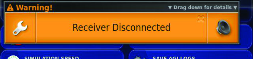
-
Wait 2 minutes for the satellite receiver and modem startup.
-
Press the EXIT SETUP icon.
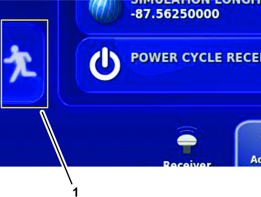
-
Rotate the ignition switch to the OFF position.
Calibrating the Compass
Perform a compass calibration at the customer’s location; refer to Calibrating the Compass in the Operator’s Manual or Software Guide for your GeoLink system.