
Introduction

CONGRATULATIONS on the purchase of your Z-Aerate. This product has been carefully designed and manufactured to give you a maximum amount of dependability and years of trouble-free operation.

This manual contains operating, maintenance, adjustment, and safety instructions for your Z-Aerate.

BEFORE OPERATING YOUR Z-AERATE, CAREFULLY READ THIS MANUAL IN ITS ENTIRETY.

By following the operating, maintenance, and safety instructions, you will prolong the life of your machine, maintain its maximum efficiency, and promote safe operation.

To maximize safety, performance, and proper operation of this machine, it is essential that all operators carefully read and fully understand the contents of the Operator’s manual provided with the product. Failure to comply with the operating instructions or receive proper training may result in injury. Go to https://www.zturfequipment.com for additional safe operation information, such as safety tips, training materials, and Operator’s manuals.

If additional information is needed, or should you require trained mechanic service, contact your authorized Z Turf Equipment dealer or distributor.

All Z Turf Equipment dealers and distributors are kept informed of the latest methods of servicing and are equipped to provide prompt and efficient service in the field or at their service stations. They carry ample stock of service parts or can secure them promptly for you from the factory.

All Z Turf Equipment parts are thoroughly tested and inspected before leaving the factory, however, attention is required on your part if you are to obtain the fullest measure of satisfaction and performance.

Whenever you need service, genuine Z Turf Equipment parts, or additional information, contact an Authorized Service Dealer or Z Turf Equipment Customer Service and have the model and serial numbers of your product ready.

g351606

For complete warranty details, see https://www.zturfequipment.com. You may also call us 402-223-6375 to request a written copy of the product’s warranty.

Important: It is a violation of California Public Resource Code Section 4442 or 4443 to use or operate the engine on any forest-covered, brush-covered, or grass-covered land unless the engine is equipped with a spark arrester, as defined in Section 4442, maintained in effective working order or the engine is constructed, equipped, and maintained for the prevention of fire.

To acquire a spark arrester for your machine, see your Engine Service Dealer.

For all models that do not have Exmark engines, please refer to the engine manufacturer's information included with the machine.

For models with Exmark engines, refer to this manual for information.

The gross or net horsepower (or torque) of this engine was laboratory rated by the engine manufacturer in accordance with the Society of Automotive Engineers (SAE) J1940 or J2723. As configured to meet safety, emission, and operating requirements, the actual engine horsepower (or torque) on this class of machine will be significantly lower.

Safety

The intended use of this machine is for lawn care.

Safety Alert Symbol

This Safety Alert Symbol (Figure 2) is used both in this manual and on the machine to identify important safety messages which must be followed to avoid accidents.

This symbol means: ATTENTION! BECOME ALERT! YOUR SAFETY IS INVOLVED!

g000502

The safety alert symbol appears above information which alerts you to unsafe actions or situations and will be followed by the word DANGER, WARNING, or CAUTION.

DANGER: Indicates an imminently hazardous situation which, if not avoided, Will result in death or serious injury.

WARNING: Indicates a potentially hazardous situation which, if not avoided, Could result in death or serious injury.

CAUTION: Indicates a potentially hazardous situation which, if not avoided, May result in minor or moderate injury.

This manual uses two other words to highlight information. Important calls attention to special mechanical information and Note emphasizes general information worthy of special attention.

General Safety

This machine is capable of amputating hands and feet and of throwing objects. Always follow all safety instructions to avoid serious personal injury or death.

  • Read, understand, and follow all instructions and warnings in the Operator’s Manual and on the machine, engine, and attachments. All operators and mechanics should be trained. If the operator(s) or mechanic(s) can not read this manual, it is the owner’s responsibility to explain this material to them; other languages may be available on our website.

  • Only allow trained, responsible, and physically capable operators that are familiar with the safe operation, operator controls, and safety signs and instructions to operate the machine. Never let children or untrained people operate or service the equipment. Local regulations may restrict the age of the operator.

  • Always use appropriate Personal Protective Equipment (PPE) to guard against contact with chemicals.

  • Do Not operate the machine near drop-offs, ditches, embankments, water, or other hazards.

  • Keep bystanders and children out of the operating area.

  • Do Not put your hands or feet near moving parts.

  • Do Not operate the machine without all safety shields, guards, switches, and other devices in place and in proper working condition.

  • Park machine on level ground, disengage drives, set parking brake, stop engine, remove key, or disconnect spark plug wire. Wait for all moving parts to stop before leaving the operator’s position. Allow the machine to cool before servicing, adjusting, fueling, unclogging, cleaning, or storing.

Safety and Instructional Decals

  • Keep all safety signs legible. Remove all grease, dirt and debris from safety signs and instructional labels.

  • Replace all worn, damaged, or missing safety signs.

  • When replacement components are installed, be sure that current safety signs are affixed to the replaced components.

  • If an attachment or accessory has been installed, make sure current safety signs are visible.

  • New safety signs may be obtained from your authorized Z Turf Equipment dealer or distributor.

  • Safety signs may be affixed by peeling off the backing to expose the adhesive surface. Apply only to a clean, dry surface. Smooth to remove any air bubbles.

  • Familiarize yourself with the following safety signs and instruction labels. They are critical to the safe operation of your Z Turf Equipment commercial aerator.

 
decal126-2055
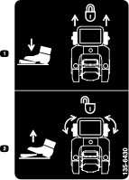
decal135-6430
decal135-6725
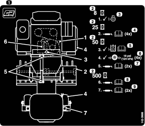
decal142-3908
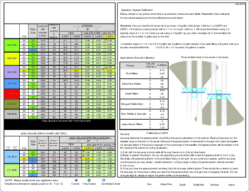
decal142-4373
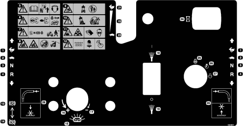
decal142-4317

Specifications

Systems

Engine

  • Engine Specifications: See your Engine Owner’s Manual

  • Engine Oil Type: Exmark 4–Cycle Premium Engine Oil

  • RPM: Full Speed: 3300 ±100 RPM (No Load)

Fuel System

  • Capacity: 5.0 gal. (18.9 L)

  • Fuel Recommendations:

    • For best results, use only clean, fresh, unleaded gasoline with an octane rating of 87 or higher ((R+M)/2 rating method).

    • Oxygenated fuel with up to 10% ethanol or 15% MTBE by volume is acceptable.

    • Do Not use ethanol blends of gasoline (such as E15 or E85) with more than 10% ethanol by volume. Performance problems and/or engine damage may result which may not be covered under warranty.

    • Do Not use gasoline containing methanol.

    • Do Not store fuel either in the fuel tank or fuel containers over the winter unless a fuel stabilizer is used.

    • Do Not add oil to gasoline.

  • Fuel Filter: Replaceable In-line

Electrical System (Electric Start)

  • Charging System: Flywheel Alternator

  • Charging Capacity: Vanguard: 16 amps

  • Battery Type: BCI Group U1

  • Battery Voltage: 12 Volt

  • Polarity: Negative Ground

  • Fuse: 10 amp main fuse

Operator Controls

  • Steering and Motion Control

    • Separate levers, on each side of the console, control speed and direction of travel of the respective drive wheels.

    • Steering is controlled by varying the position of the levers relative to each other.

  • Parking Brake Handle: Engages the parking brake.

  • Tine Adjustment Control: Raises and lowers the tines.

Transmission

  • Two Hydro Gear 16cc pumps and two Parker 280cc TG wheel motors.

  • Hydraulic Oil Type: Exmark Premium Hydro Oil

  • Hydraulic Oil Capacity: 7 qt (224 oz)

  • Hydraulic Filter is replaceable cartridge type

  • Speeds: 0-7.0 mph (11.3 km/hr) forward.

Wheel Drive System

Drive wheels driven by the pump and wheel motor transmission.

Tires and Wheels

 DriveFront Caster
 Pneumatic (Air-Filled)Pneumatic (Air-Filled)
Quantity22
Tread Super TurfRibbed
Size20 x 10.5-813 x 6.5-6
Ply Rating44
Pressure18 ±2 psi (110-138 kPa)18 ±2 psi (110-138 kPa)

Aeration

Aeration Width: 40 inches (101.6 cm)

Tines: Qty: 60

Core Depth: 0.5-3 inches (5.1-12.7 cm)

Holes per square foot: 4.8

Dimensions

Overall Width:

46 inches (116.8 cm)

Overall Length:

84.8 inches (215.4 cm)

Overall Height:

49.5 inches (125.7 cm)

Tread Width: (Outside to Outside of Tires, Widthwise)

46 inches (116.8 cm)

Curb Weight:

1460 lb (662 kg)

Torque Requirements

Bolt LocationTorque
Engine Mounting Bolts121-144 in-lb (13.3-15.8 N-m)
Wheel Lug Nuts86-104 ft-lb (116.3-141 N-m)
Wheel Hub Nuts211-260 ft-lb (286-352 N-m)

Product Overview

g349230

Operation

Note: Determine the left and right sides of the machine from the normal operating position.

Controls

Become familiar with all the controls before starting the engine and operating the machine.

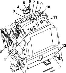
Motion Control Levers

The motion control levers, located on each side of the top console, control the forward and reverse motion of the machine.

Moving the levers forward or backward turns the wheel on the same side forward or reverse respectively. Wheel speed is proportional to the amount the lever is moved.

g315941

Choke Control

Located on the control console (black knob) (see Figure 5).

The choke is used to aid in starting a cold engine. Pulling the choke knob up will put the choke in the “ON” position and pushing the choke knob down, will put the choke in the “OFF” position. Do Not run a warm engine with choke in the “ON” position.

g316004

Throttle Control

Located on the control console (black lever) (see Figure 5).

The throttle is used to control engine speed. Moving the throttle lever forward will increase engine speed and moving the throttle lever to the rear will decrease engine speed. Moving the throttle forward into the detent is full throttle.

Park Brake Handle

Located on the left side of the tower (see Figure 5).

The brake handle engages a parking brake.

To engage the brake, pull handle toward the back of the machine.

To release, push the handle forward.

When parking on a steep slope, the wheels must be chocked or blocked in addition to the brake being engaged. The machine must be tied down and brake engaged when transporting.

Ignition Switch

Located on the right side of the control console.

The ignition switch is used to start and stop the engine. The switch has three positions “OFF”, “ON” and “START”. Insert key into switch and rotate clockwise to the “ON” position. Rotate clockwise to the next position to engage the starter (key must be held against spring pressure in this position). Allow the key to return to the “ON” position immediately after the engine starts.

Hour Meter

Located to the right of the throttle.

The hour meter is connected to a charge circuit installed in the engine block and it records the number of hours that the engine has run. If ignition switch is left on without engine running, hour meter will not run.

Spreader Impeller Speed Control

Located on the left side of the control console (see Figure 5).

Rotate the knob counterclockwise to start the impeller and to increase the speed and pattern width. Rotate the knob clockwise to decrease speed, pattern width, and to turn the impeller off.

Digital Display Gauge

Located in front of the throttle control.

Refer to the digital display User’s Manual for the display information.

Spreader On/Off

Located above the digital display gauge.

Pull the handle up to open the hopper gate. Push the handle down to close the hopper gate.

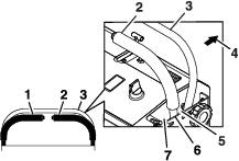
Spread Pattern Control

Located on the right side of the control tower and is the middle cable.

This control is used if the spread pattern is skewed or dispensing too light/heavy to one side.

Rotate the handle counterclockwise 90 degrees to unlock. If pattern is heavy to the left; push the handle down; if heavy to the right, pull the handle up. Rotate the handle clockwise 90 degrees to lock.

Spreader Deflector

Use the deflector to temporarily stop or deflect granules away from sidewalks, parking lots, patios, or anywhere granules are not desired to be discharged from the left side of the spreader.

g317335

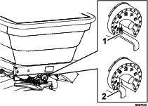
Rate Dial and Linkage

Located at the front of the machine below the spreader hopper.

The rate dial and linkage is used to set the amount of material to be dispensed from the hopper gate (see Figure 7).

g027033

With the Spreader On/Off handle in the “OFF” (closed) position, turn the dial to the appropriate setting. When the Spreader On/Off is pulled to the “ON” position, the gate will open to the set position.

Note: The slot, after setting 9 on the dial, allows the hopper gate to be opened to the maximum position. This setting can be used for dry sand, ice melt, or other materials that are difficult to spread; it may also be used for hopper cleanout (see Cleaning the Spreader section).

Drive Wheel Release Valves

Warning

The engine and hydraulic drive units can become very hot. Touching a hot engine or hydraulic drive units can cause severe burns.

Allow the engine and hydraulic drive units to cool completely before accessing the drive wheel release valves.

Located on the left and right sides underneath the control tower.

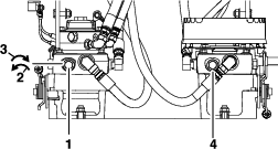
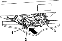
During normal operating conditions, the release valve nut should be tight. To tighten, rotate the nut clockwise until snug (Figure 8). If the machine has to be pushed by hand, loosen the nut by rotating counterclockwise one turn. (see Figure 8).

g310379

Release the parking brake. The machine is now able to be pushed by hand.

Do Not tow machine.

To reset the drive system back to the operating position: Tighten the nut by rotating clockwise until snug. Repeat this on each side of the machine.

Tines Ground Engagement Thumb Switches

Keep hands and feet away from the tines. Ensure that the tine area is clear of any obstructions before lowering.

The switches are located in the end of the motion control levers (see Figure 5).

To lower the tines into the ground, press the left thumb switch and hold until the tines reach the desired depth. To raise the tines, press the right thumb switch and hold until the tines are at the desired height.

Important: The tines are rotating when the tines are lowered and the motion control lever is moved out of the neutral position.

Caster Wheel Lock Foot Pedal

Located on the right side of the operator platform (see Figure 5).

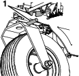
Press and hold the caster wheel lock foot pedal to lock the caster wheels in the straight position. Release the foot pedal to unlock the caster wheels and allow the machine to freely turn.

g271157

Before Operation

Before Operation Safety

  • Evaluate the terrain to determine what accessories and attachments are needed to properly and safely perform the job. Only use accessories and attachments approved by Z Turf Equipment.

  • Inspect the area where the machine is to be used and remove all rocks, toys, sticks, wires, bones, and other foreign objects. These can be contaminated by chemicals, thrown or interfere with the operation of the machine and may cause personal injury to the operator or bystanders.

  • Mark and avoid hidden objects such as sprinkler heads, underground wires/cables, invisible fences, etc. to prevent damage to these systems when aerating.

  • This machine was designed for one operator only. Do Not carry passengers.

  • Wear appropriate personal protective equipment such as safety glasses, long pants, substantial slip-resistant footwear, and hearing protection. Tie back long hair and avoid loose clothing and loose jewelry which may get tangled in moving parts.

  • This machine produces sound levels in excess of 85 dBA at the operator’s ear and can cause hearing loss through extended periods of exposure. Wear hearing protection when operating this machine.

  • Check that the following items are in place and in proper working condition: the operator presence controls, safety switches, guards, and shields. Do Not operate the machine unless they are in proper working condition. Replace worn or deteriorated parts with genuine Z Turf Equipment parts when necessary.

    Danger

    It is essential that operator safety mechanisms be connected and in proper operating condition prior to use.

    Shut off the engine, remove the key, and wait for all moving parts to stop before leaving the operating position. When the key is turned to the “OFF” position, the engine should shut off. If not, stop using the machine immediately and contact an Authorized Service Dealer.

  • Do Not operate the machine when people, especially children, or pets are in the area. Shut off the machine and attachment(s) if anyone enters the area.

  • Do Not operate the machine without the safety devices in place and in proper working condition. Components are subject to wear, damage and deterioration, which could expose moving parts or allow objects to be thrown. Frequently check for worn or deteriorating components and replace them with the manufacturer’s recommended parts when necessary.

  • Do Not fill, calibrate, or clean the machine when people, especially children, or pets are in the area.

  • Make sure the operator platform is clean and free from chemical residue and debris buildup.

Chemical Safety

Warning

Chemical substances used in the spreader system may be hazardous and toxic to you, bystanders, animals, plants, soils or other property.

  • Carefully read and follow the chemical warning labels and Material Safety Data Sheets (MSDS) for all chemicals used and protect yourself according to the chemical manufacturer's recommendations. Ensure that as little skin as possible is exposed while using chemicals. Use appropriate Personal Protective Equipment (PPE) to guard against personal contact with chemicals, such as:

    – safety glasses, goggles, and/or face shield

    – chemical resistant gloves

    – rubber boots or other substantial footwear

    – hearing protection

    – respirator or filter mask

    – clean change of clothes, soap, and disposable towels, to be kept on-hand, in the event of a chemical spill.

  • Keep in mind that there may be more than one chemical used, and information on each chemical should be assessed.

  • Refuse to operate or work on the spreader if this information is not available!

  • Before working on a spreader system, make sure that the system has been triple rinsed and neutralized according to the recommendations of the chemical manufacturer(s).

  • Verify there is an adequate supply of clean water and soap nearby, and immediately wash off any chemicals that contact you.

  • Obtain proper training before using or handling chemicals.

  • Use the correct chemical for the job.

  • Follow the chemical manufacturer's instructions for the safe application of the chemical and Do Not exceed recommended system application pressure.

  • Handle chemicals in a well ventilated area.

  • Have clean water available.

  • Do Not eat, drink, or smoke while working with chemicals.

  • Always wash your hands and other exposed areas as soon as possible after finishing the work.

  • Keep chemicals in their original packages and in a safe location.

  • Properly dispose of unused chemicals and chemical containers as instructed by the chemical manufacturer and your local codes.

  • Chemicals and fumes are dangerous; never enter the hopper or place your head over or in the opening.

  • Follow all local/state/federal requirements for the spreading of chemicals.

Fuel Safety

Danger

Gasoline is extremely flammable and vapors are explosive.

A fire or explosion from gasoline can burn you, others, and cause property damage.

  • Fill the fuel tank outdoors on level ground, in an open area, when the engine is cold. If fuel is spilled, Do Not attempt to start the engine. Move away from the area of the spill and avoid creating any source of ignition until fuel vapors have dissipated.

  • Do Not refill the fuel tank or drain the machine indoors or inside an enclosed trailer.

  • Never smoke when handling gasoline, and stay away from an open flame or where gasoline fumes may be ignited by spark.

  • Add fuel before starting the engine. Never remove the cap of the fuel tank or add fuel when engine is running or when the engine is hot.

  • Store gasoline in an approved container and keep it out of the reach of children.

  • Do Not operate without entire exhaust system in place and in proper working condition.

  • In certain conditions during fueling, static electricity can be released causing a spark which can ignite gasoline vapors.

    • Do Not fill containers inside a vehicle or on a truck or trailer bed with a plastic liner. Always place containers on the ground and away from your vehicle before filling.

    • When practical, remove gas-powered equipment from the truck or trailer and refuel the equipment with its wheels on the ground. If this is not possible, then refuel such equipment on a truck or trailer from a portable container, rather than from a gasoline dispenser nozzle.

    • If a gasoline dispenser nozzle is used, keep the nozzle in contact with the rim of the fuel tank or container opening at all times until fueling is complete. Do Not use a nozzle lock open device.

  • Do Not overfill the fuel tank. Fill the fuel tank to the bottom of the filler neck. The empty space in the tank allows gasoline to expand. Overfilling may result in fuel leakage or damage to the engine or emission system.

  • Gasoline is harmful or fatal if swallowed. Long-term exposure to vapors may cause serious injury and illness.

    • Avoid prolonged breathing of vapors.

    • Keep face away from nozzle and gas tank/container opening.

    • Keep away from eyes and skin.

  • To help prevent fires:

    • Keep engine and engine area free from accumulation of grass, leaves, excessive grease or oil, and other debris which can accumulate in these areas.

    • Clean up oil and fuel spills and remove fuel soaked debris.

    • Allow the machine to cool before storing the machine in any enclosure. Do Not store the machine or fuel container, or refuel, where there is an open flame, spark, or pilot light such as on a water heater or other appliance.

Operating Instructions

During Operation Safety

General Safety

The operator must use their full attention when operating the machine. Do Not engage in any activity that causes distractions; otherwise, injury or property damage may occur.

Warning

Operating engine parts, especially the muffler, become extremely hot. Severe burns can occur on contact and debris, such as leaves, grass, brush, etc. can catch fire.

  • Allow engine parts, especially the muffler, to cool before touching.

  • Remove accumulated debris from muffler and engine area.

Caution

Chemicals are hazardous and can cause personal injury.

  • Read the directions on the chemical labels before handling the chemicals and follow all manufacturer recommendations and precautions.

  • Keep chemicals away from your skin. Should contact occur, wash the affected area thoroughly with soap and clean water.

  • Wear goggles, gloves, and any other protective equipment recommended by the chemical manufacturer.

  • Operate the engine only in well-ventilated areas. Exhaust gases contain carbon monoxide, which is an odorless deadly poison.

  • Do not operate the machine while ill, tired, or under the influence of alcohol or drugs.

  • Operate the machine only in good visibility and appropriate weather conditions. Do Not operate the machine when there is the risk of lightning.

  • Keep away from holes, ruts, bumps, rocks, and other hidden hazards. Use care when approaching blind corners, shrubs, trees, tall grass or other objects that may hide obstacles or obscure vision. Uneven terrain could overturn the machine or cause the operator to lose their balance or footing.

  • Start the engine with your feet well away from the tines and spreader discharge areas.

  • Do Not operate the machine without all safety shields, guards, switches, and other devices in place and in proper working condition.

  • Keep clear of the discharge area at all times.

  • Keep your hands and feet away from the moving parts. Keep clear of the tines and discharge area at all times.

  • Be aware of the discharge/spreading path and direct discharge away from others. Avoid discharging material against a wall or obstruction as the material may ricochet back toward the operator. Raise the tines, slow down, and use caution when crossing surfaces other than grass and when transporting the machine to and from the work area.

  • Be alert, slow down and use caution when making turns. Look behind and to the side before changing directions. Do Not operate in reverse unless absolutely necessary.

  • Stop spreading when making tight turns to minimize uneven distribution pattern, application rate, and chemical drift.

  • Chemicals may drift and cause injury to people and animals; it may also damage plants, soil, or other property.

  • Park the machine on level ground. Stop engine, wait for all moving parts to stop, and remove key.

    • Before checking, cleaning or working on the machine.

    • After striking a foreign object or abnormal vibration occurs (inspect the machine for damage and make repairs before restarting and operating the machine).

    • Before clearing blockages.

    • Whenever you leave the machine. Do Not leave a running machine unattended.

  • Stop engine, wait for all moving parts to stop, and engage parking brake:

    – Before refueling

  • Tragic accidents can occur if the operator is not alert to the presence of children. Children are often attracted to the machine and the working activity. Never assume that children will remain where you last saw them.

    • Keep children out of the working area and under the watchful care of another responsible adult, not the operator.

    • Be alert and turn the machine off if children enter the area.

    • Before and while backing or changing direction, look behind, down, and side-to-side for small children.

    • Never allow children to operate the machine.

    • Do Not carry children, even if the aerator or spreader is not in use. Children could fall off and be seriously injured or interfere with the safe operation of the machine. Children that have been given rides in the past could suddenly appear in the working area for another ride and be run over or backed over by the machine.

  • Reduce the weight of the load when operating on hills and rough terrain to avoid tipping or overturning of the machine.

  • Granular materials can shift. This shifting happens most often while turning, going up or down hills, suddenly changing speeds, or while driving over rough surfaces. Shifting loads can cause the machine to tip over.

  • When operating with a heavy load, reduce your speed and allow for sufficient stopping distance. Use extra caution on slopes.

  • Reduce speed and load when operating on rough terrain, uneven ground, and near curbs, holes, and other sudden changes in terrain. Loads may shift, causing the machine to become unstable.

    Warning

    Sudden changes in terrain may cause abrupt steering wheel movement, possibly resulting in hand and arm injuries.

    Reduce speed when operating on rough terrain or near curbs.

Slope Safety

  • Slopes are a major factor related to loss of control and rollover accidents, which can result in severe injury or death. The operator is responsible for safe slope operation. Operating the machine on any slope requires extra caution. Before using the machine on a slope, the operator must:

    • Review and understand the slope instructions in the manual and on the machine.

    • Evaluate the site conditions of the day to determine if the slope is safe for machine operation. Use common sense and good judgment when performing this evaluation. Changes in the terrain, such as moisture, can quickly affect the operation of the machine on a slope.

  • Operate across slopes, never up and down. Avoid operation on excessively steep or wet slopes.

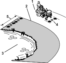
  • Identify hazards at the base of the slope. Do not operate the machine near drop offs, ditches, embankments, water or other hazards. The machine could suddenly roll over if a wheel goes over the edge or the edge collapses. Keep a safe distance (twice the width of the machine) between the machine and any hazard. Use a walk behind machine or a hand held tool to operate in these areas.

    g317101
  • Avoid starting, stopping or turning the machine on slopes. Avoid making sudden changes in speed or direction; turn slowly and gradually.

  • Do not operate a machine under any conditions where traction, steering or stability is in question. Be aware that operating the machine on wet grass, across slopes or downhill may cause the machine to lose traction. Loss of traction to the drive wheels may result in sliding and a loss of braking and steering. The machine can slide even if the drive wheels are stopped.

  • Remove or mark obstacles such as ditches, holes, ruts, bumps, rocks or other hidden hazards. Tall grass can hide obstacles. Uneven terrain could overturn the machine.

  • Use extra care while operating with accessories or attachments. These can change the stability of the machine and cause a loss of control. Follow directions for counter weights.

  • If you lose control of the machine, step off and away from the direction of travel of the machine.

Starting the Engine

  1. Leave the motion control levers in neutral and engage the parking brake.

  2. Set the throttle to the “FAST” position.

  3. On a cold engine, pull the choke knob upward into the “ON” position. On a warm engine, leave the choke in the “OFF” position.

  4. Turn ignition switch to the “START” position. Release the switch as soon as the engine starts.

    Important: Do Not crank the engine continuously for more than ten seconds at a time. If the engine does not start, allow a 60 second cool-down period between starting attempts. Failure to follow these guidelines can burn out the starter motorEngine may be difficult to start in temperatures under 30°F (-1 °C).

  5. If the choke is in the “ON” position, gradually return choke to the “OFF” position as the engine warms up.

Lowering the Tines

Danger

The rotating tines are dangerous. Tine contact can cause serious injury or death.

Do Not put hands or feet under the machine when the engine is running.

  1. Disengage the parking brake. Set throttle to “FAST” position.

  2. Press the thumb switch until desired tine depth is achieved.

    Important: The tines are rotating when the tines are lowered and the motion control lever is moved out of the neutral position.

  3. Once desired tine depth is achieved, move the motion control levers forward to aerate.

Important: Keep the drive tires on the ground at all times to maximize lateral machine stability and aeration quality.

Raising the Tines

To raise the tines, press the right thumb switch until the tines reach desired height, then release.

Stopping the Engine

  1. Move the motion control levers back to the neutral position and bring the machine to a full stop.

  2. Press the right thumb switch until the tines reach desired height, then release.

  3. Place the throttle midway between the “SLOW” and “FAST” positions.

  4. Allow the engine to run for a minimum of 15 seconds, then turn the ignition switch to the “OFF” position to stop the engine.

  5. Engage the parking brake.

  6. Remove the key to prevent children or other unauthorized persons from starting the engine.

Driving the Machine

Caution

Machine can spin very rapidly by positioning one lever too much ahead of the other. Operator may lose control of the machine, which may cause damage to the machine or injury.

  • Use caution when making turns.

  • Slow the machine down before making sharp turns.

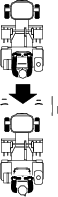
Important: To begin movement (forward or backward), the brake lever must be disengaged (pushed forward) before the motion control levers can be moved.

g315941

Driving Forward

  1. Make sure the motion control levers are in the neutral position.

  2. Release the parking brake.

  3. To move forward in a straight line, move both levers forward with equal pressure.

    g317231

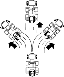
    To turn left or right, pull the motion control lever back toward neutral in the desired turn direction. The tines can be in the down position when making gradual turns.

    To make zero turns, raise the tines using the right thumb switch.

    Important: Do Not make a zero turn when the tines are down as turf tearing will result.

    The machine will move faster the farther the motion control levers are moved from the neutral position.

  4. To stop, position both motion control levers in the neutral operate position.

    Note: Stopping distance may vary depending on the spreader load.

Driving in Reverse

  1. Move the motion control levers to the neutral operate position.

  2. To move rearward in a straight line, slowly move both levers rearward with equal pressure.

    Important: Do Not drive in reverse when the tines are down as turf tearing will occur.

    g317334

    To turn left or right, release pressure on the motion control lever toward the desired turn direction.

    To make zero turns, raise the tines using the right thumb switch.

    Important: Do Not make a zero turn when the tines are in the down position.

  3. To stop, position both motion control levers in the neutral operate position.

    Note: Stopping distance may vary depending on the spreader load.

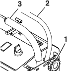
Adjusting the Front Reference/Speed Control Bar

Adjust the front reference/speed control bar for desired maximum forward speed.

  1. Stop the machine and move the motion control levers to the neutral position.

  2. Loosen the knobs on each side of the control panel (see Figure 14).

    g316064
  3. Move the bar forward to obtain the fastest speed.

    Move the bar backward to obtain the slowest speed.

  4. On both sides, tighten the knobs.

Important: Make sure the knobs are tight so the front reference/speed control bar does not move during operation.

Operating the Spreader

The spreader disperses free-flowing granular substances such as grass seed, fertilizer, ice melt, etc. When using the spreader, first fill the granule hopper, then apply to the work area, and finally clean the hopper. It is important to complete all three of these steps to avoid damaging the spreader.

Note: Clean your spreader thoroughly after all applications.

Before Operating the Spreader

Make sure the spreader has been calibrated for the material to be spread before starting (see Calibrating the Spreader section).

Important: Verify that the proper application rate has been set prior to filling the hopper.

Filling the Spreader Hopper

  1. Stop the machine on a level surface, move motion control lever to the neutral position, stop the engine, and set the parking brake.

  2. Use the Spreading Chart on the following pages to determine the rate dial and linkage.

    Note: If the setting is not listed for the type of material being used, place the setting at a lower value then adjust as needed.

  3. Drive to the work area.

  4. Stop the machine on a level surface, leave motion control lever in the neutral position, stop the engine, and set the parking brake.

  5. Ensure that the hopper gate is closed.

  6. Remove the cover from the hopper, add the material to be spread, and replace the cover.

    Note: Do Not overload the hopper (refer to the Maximum Hopper Capacity in Specifications section).

    Note: Do Not exceed the Maximum Machine Weight as stated in the Specifications section. Overloading the machine will shorten the life of the transmission and void the warranty.

Spreading

Spreading Tips:

  • To ensure uniform application, be sure to overlap the material distribution. The highest amount of material will dispense from the front of the hopper and less material from each side. Adjust the distribution pattern to achieve desired results.

  • Watch for changes in the distribution pattern; unequal distribution may lead to striping.

Note: Make sure the machine has been calibrated properly before starting the spreading application.

  1. Start the engine and place the throttle midway between the “SLOW” and “FAST” positions.

  2. Set the impeller speed to appropriate broadcast rate setting.

  3. Move the throttle to the “FAST” position and drive forward.

  4. Pull the Spreader On/Off handle up to open the hopper gate and begin spreading.

    g317336
    g317335
  5. Evaluate the spread pattern. If adjustments are needed see the Spreader Calibration/Pattern Adjustment section.

  6. When finished spreading, close the hopper gate.

  7. Clean the hopper after each spreading session.

    Important: Always empty and clean the spreader immediately after each use. Failure to do so may cause the chemicals to corrode the spreader and other components.

Cleaning the Spreader

  1. Drive the machine to a designated cleaning area.

  2. Stop the machine on a level surface, leave the motion control lever in the neutral position, and turn off the engine. Engage the parking brake.

  3. With the hopper empty, push inward on the ball joint sleeve and pull off cable end to release the gate lever. Push the gate lever inward to fully open the drain hole.

    g027034
  4. Open the hopper gate to the maximum position by pulling the rate dial and linkage outward. Rotate the dial past the “9” position to the slot opening and push in the linkage.

  5. Using a garden hose, spray the inside and outside of the entire spreader with clean water.

    Note: Do Not use a power washer to clean the machine. The high pressure water may force residual corrosive materials into spreader components.

  6. When the hopper has been thoroughly rinsed and drained, close the gate.

  7. Place the rate dial and linkage to a setting lower than the maximum open position.

  8. Allow the spreader to completely dry before the next use.

  9. Lightly oil spreader components to help reduce corrosion.

Spreader Calibration

The spreader should be calibrated each time a new material is used. The spread width ranges from 3-25 ft (0.9-7.6 m) and depends on the material particle size, volume/density, and rate of travel.

Refer to the spreading charts along with Determining the Distribution Pattern, Determining the Effective Spreading Width, and Calculating the Application Rate sections to calibrate the machine.

Determining the Distribution Pattern

Important: The tines are rotating when the tines are lowered and the motion control lever is moved out of the neutral position. Make sure the tines are raised all the way up before starting this procedure.

Operator supplied equipment: 15 shallow collection pans and 15 graduated measuring cylinders

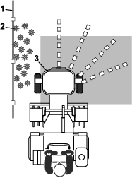
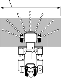
The most accurate method to measure the distribution is to use shallow collection pans and graduated measuring cylinders. In the example below, 15 shallow collection pans approximately 30 cm (12 inches) wide, 91 cm (36 inches) long, and 5 cm (2 inches) tall are used.

  1. Make sure to allow ample driving distance before setting up the pans to ensure the machine is traveling at the desired spreading speed before reaching the pans.

  2. Place one pan in the center of the drive path. Arrange the next two pans, one on each side, far enough apart to allow ample room for the spreader drive tires to pass over the center pan.

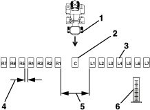
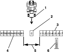
  3. Place the remaining pans in a straight line as shown in Figure 18 or Figure 19.

    • For larger granule materials:

      Space six additional pans, on each side, 12 inches (30 cm) apart (see Figure 19).

      g317337
    • For smaller granule materials:

      Place six additional pans, on each side, with no gap in between each pan (Figure 19).

      g317338
  4. Reference the Spreading Charts section to determine the appropriate rate dial setting (see Figure 7).

  5. Fill the hopper approximately half-full with the desired material.

  6. Set the impeller speed to the appropriate broadcasting rate.

  7. Pull the granular gate control to the open position and drive the spreader, at the appropriate speed, over the center pan. Repeat this several times, moving in the same direction each time, until enough material is dispensed to fill the center graduated measuring cylinder half full.

  8. Label each graduated measuring cylinder to correspond with the distribution pans (i.e. ...L2, L1, Center, R1, R2....) (reference Figure 18 and Figure 19).

  9. One at a time, take a collection pan and dump the contents into the corresponding graduated measuring cylinder. Record the amount of material collected and return the pan to its location. Repeat this until all pan contents have been emptied.

  10. With the graduated measuring cylinder in the same straight line as the pans, evaluate the volume of material in each cylinder to determine the quality of the distribution from the spreader.

  11. To adjust the spreader pattern, refer to the Spreader Pattern Adjustment section.

  12. Repeat steps 5 through 11 until an uniform pattern is achieved.

Determining the Effective Spreading Width

The effective width is used to determine the uniform distribution of the material.

Note: The spreading width range is 3 ft (0.9 m) up to 25 ft (7.6 m).

  1. After the spreader pattern is correctly adjusted, evaluate the amount of material in the center graduated measuring cylinder.

  2. Locate the two tubes, one each side of center, that contain 1/2 the measured amount of the material that you observed in the center graduated cylinder.

  3. Go to the two corresponding pans. Starting from the outer edge, measure and record the distance between left pan, through the center pan, to the outer edge of the right pan.

    Note: This measurement is the effective spreading width.

Calculating the Application Rate

  1. Determine the amount of product to be applied.

  2. Determine the calibration course

    1. Determine the amount of product to be spread per 1,000 ft2 (93 m2). Use the recommended rate from the Spreading Charts section or the product manufacturer’s label as a guide.

    2. Determine a course length by dividing 1,000 ft2 (93 m2) by the effective spread width.

      For example, if the effective width is 6 feet (1.8 meters), then the calibration course length equals 167 ft (51 m).

      Course Length

       1,000 ft2 (93 m2)=167 ft (51 m)
        6 ft (1.8 m)
    3. The calibration course is 6 ft (1.8 m) by 167 ft (51 m).

    4. Measure and visibly mark the course length. Make sure to allow ample distance before the starting marker to ensure the spreader is at full speed when crossing the first mark of the course.

  3. Set the appropriate gate dial setting (reference the Spreading Charts section as a starting point).

  4. Add material to the hopper (for example, 25 lb (11.3 kg) was added).

  5. Drive the spreader over the calibration course while applying the material.

  6. Empty the remaining material of the hopper into a clean bucket.

  7. Weigh the bucket containing the material and record the weight. Pour the contents back into the hopper and then weigh the empty bucket. Subtract these two amounts to determine the amount of material remaining in the hopper (for example, 20 pounds (9 kg) remains.)

  8. Subtract the amount remaining in the hopper (step 7) from the amount originally added (step 4); the result is the amount applied to the course.

    Amount Applied

    25 lb (11.3 kg) – 20 lb (9 kg)=5 lb (2.3 kg)

    For this example, 5 lb (2.3 kg) was applied to 1,000 ft2 (93 m2).

  9. If necessary, adjust the rate dial to achieve the recommended amount to be applied and repeat the procedure. Once the correct application rate is achieved, repeat this procedure an additional time to verify the results.

    Note: Designate a new calibration course each time, so the turf is not damaged.

Spreader Pattern Adjustment

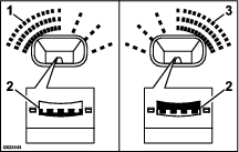
If the spread pattern is skewed or dispensing too light/heavy to one side (see Figure 20 and Figure 21), adjust the gate as follows:

g025543

Note: Do Not adjust the ramps to split product flow. Use only the front or rear ramp positions as shown.

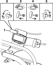
  1. Unlock the spreader pattern control by turning the handle counterclockwise 90 degrees (see Figure 21).

    To adjust when the material pattern is heavy:

    • to the left side, slightly push the handle down.

    • to the right side, slightly pull the handle up.

    g317043
  2. Lock the spreader pattern control by turning the handle clockwise 90 degrees.

Spreading Charts

Note: The Dial Settings chart and the Grass Seed Spreading chart are provided with permission from the Brinly-Hardy Company; reference the Brinly-Hardy Company website for more information.

These charts are to be used as an approximate guideline only. Other factors, such as weather conditions, spreader operation, and condition of materials, will affect the results.

Approximate Dial Settings
Type1,000 ft2(93 m2 )Dial Setting — One Pass Dial Setting — Two Passes
Fine Pellets1 lb (.45 kg)3.63.1
2 lb (.91 kg)4.03.5
3 lb (1.36 kg)4.23.7
Mixed Fine Pellets2 lb (.91 kg)3.73.2
4 lb (1.81 kg)4.74.1
6 lb (2.72 kg)5.24.5
Small Pellets2 lb (.91 kg)32.2
4 lb (1.81 kg)4.23.7
6 lb (2.72 kg)4.54
Nitrogen Pellets Medium Size1 lb (.45 kg)3.53
2 lb (.91 kg)4.23.7
3 lb (1.36 kg)4.74
Medium Pellets and Granules2 lb (.91 kg)3.53
4 lb (1.81 kg)4.23.8
6 lb (2.72 kg)5.24.5
Large Heavy Pellets2 lb (.91 kg)3.83.3
4 lb (1.81 kg)4.94.1
6 lb (2.72 kg)5.94.9

The chart below is for reference only. When spraying and spreading at the same time, set the spread pattern to twice the width of the spray; this will help avoid striping and streaking. For example, standard spray width = 9 ft (2.7 m) and spread width = 18 ft (5.4 m).

Grass Seed Application(Coverage 1,000 ft2 (93 m2))
TypeBag WeightDial Setting – Full RateDial Setting – Half RateSpread Width
Blue Grass or Red Top.5 lb1.25 4 ft (1.2 m)
1 lb2.0 4 ft (1.2 m)
2 lb2.5 4 ft (1.2 m)
Park, Merion, Delta, or Kentucky Bluegrass.5 lb2.5 4 ft (1.2 m)
1 lb3.0 4 ft (1.2 m)
2 lb3.5 4 ft (1.2 m)
Hulled Bermuda2 lb2.752.256 ft (1.8 m)
3 lb3.02.56 ft (1.8 m)
4 lb3.252.756 ft (1.8 m)
Mixtures Including Coarse Seeds2 lb6.0 6 ft (1.8 m)
4 lb7.0 6 ft (1.8 m)
6 lb7.0 6 ft (1.8 m)
Rye Grasses or Tall Fescue2 lb6.0 6 ft (1.8 m)
4 lb7.0 6 ft (1.8 m)
6 lb7.75 6 ft (1.8 m)
Dichondra4 oz1.9 8 ft (2.4 m)
8 oz2.1 8 ft (2.4 m)
12 oz2.5 8 ft (2.4 m)
Pensacola Bahia4 lb4.53.757 ft (2.1 m)
5 lb4.754.07 ft (2.1 m)
6 lb5.04.257 ft (2.1 m)

Removing the Aerator Head

The aerator head can be removed for service, cleaning and or to install other attachments. To remove the aerator head from the traction unit:

  1. Adjust the hydraulic cylinder so that the aerator head starts to make contact with the ground (taking weight off of the head).

  2. Stop engine, wait for all moving parts to stop, engage the parking brake, and remove the key.

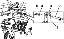
  3. Remove the cotter pin, washer, and hitch pin to disconnect the aerator rear frame from the lift arm center linkage ball swivel.

    g349475
  4. Start the machine and lower the cylinder, releasing tension from the chains.

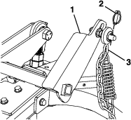
  5. Remove and retain the two lynch pins located on each side of the lift arm assembly. Remove the swivel chain assemblies and replace with the lynch pins back into the lift arm assembly.

    g348280
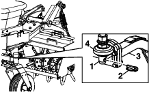
  6. Remove the lynch pin from the lift arm pin on the machine and pull the neck downward to dismount the ball swivel. Reinstall the lynch pin into the lift arm pin.

    g349473
  7. Lower the aerator front frame neck and block up the aerator so it can be stored safely and to make future reinstallation easier.

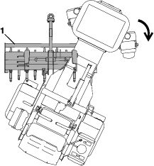
  8. Drive away from the aerator head by turning either left or right (turning to the right of the head — reference Figure 25).

    g286624

    Note: The removable weights are heavy. Use care when lifting them. Make sure that you can hold them securely before lifting them. Use caution when positioning your hands so that you Do Not set them on your hands, fingers, or feet. It is recommended to use two people when removing weights.

Installing the Aerator Tine Head

  1. Remove and retain the cotter pin, washer and hitch pin from the center linkage ball swivel as shown in Figure 26.

    g348159
  2. Remove and retain the lynch pin from the lift arm pin towards the front of the machine (reference Figure 26).

  3. Lift the accessory front frame neck and insert the lift arm pin on the machine into the ball swivel. Secure the accessory by reinserting the lynch pin (reference Figure 24).

  4. Remove and retain the two lynch pins located on each side of the lift arm assembly (reference Figure 23). Start the machine and lower the cylinder until the two swivel chain assemblies on the accessory can be connected to the lift arm assembly. Install the swivel chain assemblies and secure with the lynch pins.

  5. Using the hydraulic cylinder, raise or lower the lift arm center linkage until the ball swivel aligns with the mounting holes in the rear frame of the accessory (reference Figure 22).

    Note: Small adjustments may need to be made to the center linkage when attaching the accessory.

  6. Shut off the engine, wait for all moving parts to stop, and remove key.

  7. Install the hitch pin, washer, and cotter pin to retain the accessory to the center linkage ball swivel.

After Operation

General Safety

  • Park machine on level ground, disengage drives, set parking brake, stop engine, and remove key. Wait for all moving parts to stop before leaving the operator’s position. Allow the machine to cool before servicing, adjusting, fueling, unclogging, cleaning, or storing.

  • Clean grass, leaves, excessive grease or oil, and other debris from the muffler, drives, and engine area to help prevent fires.

  • Close the fuel shut-off valve before storing or transporting the machine.

Transporting

Note: Refer to the chemical warning product label(s) before transporting the machine and follow all local/state/federal requirements for transporting chemicals.

Note: Make sure the spreader hopper cover is secure before transporting.

Transporting the Machine

Use a heavy-duty trailer or truck to transport the machine. Ensure that the trailer or truck has all necessary lighting and marking as required by law. Thoroughly read all of the safety instructions. Knowing this information could help you, your family, pets, or bystanders avoid injury.

To transport the machine:

  • Lock the brake and block the wheels.

  • Securely fasten the machine to the trailer or truck with straps, chains, cable, or ropes. If possible, both front and rear straps should be directed down and outward from the machine. Only use the four designated tie-down locations on the machine-two on the left side and two on the right (see Figure 27). Use these locations even when transporting the machine with an attached accessory. Using non-designated locations may cause damage to the machine and/or attachment.

    g317044
  • Secure a trailer with safety chains.

    Warning

    Securing the machine on any upper frame location will cause the parking brake to not function properly, which could cause serious injury or death.

    Only use the front tie down locations on the lower frame to secure the machine.

    Warning

    Driving on the street or roadway without turn signals, lights, reflective markings, or a slow moving vehicle emblem is dangerous and can lead to accidents causing personal injury.

    Do not drive machine on a public street or roadway.

Loading the Machine

Use extreme caution when loading machines on trailers or trucks. One full width ramp that is wide enough to extend beyond the rear tires is recommended instead of individual ramps for each side of the machine. A full width ramp provides a surface to walk on behind the machine. If it is not possible to use one full width ramp, use enough individual ramps to simulate a full width continuous ramp.

A steep ramp angle may cause components to get caught as the machine moves from ramp to trailer or truck. Steeper angles may also cause the machine to tip backward. If loading on or near a slope, position the trailer or truck so it is on the down side of the slope and the ramps extends up the slope. This will minimize the ramp angle. The trailer or truck should be as level as possible.

Important: Do Not attempt to turn the machine while on the ramp, you may lose control and drive off the side.

Avoid sudden acceleration when driving up a ramp and sudden deceleration when backing down a ramp. Both maneuvers can cause the machine to tip backward.

Warning

Loading a machine on a trailer or truck increases the possibility of backward tip-over. Backward tip-over could cause serious injury or death.

  • Use extreme caution when operating a machine on a ramp.

  • Use only a single, full width ramp; Do Not use individual ramps for each side of the machine.

  • If individual ramps must be used, use enough ramps to create an unbroken ramp surface wider than the machine.

  • Avoid sudden acceleration while driving machine up a ramp to avoid tipping backward.

  • Avoid sudden deceleration while backing machine down a ramp to avoid tipping backward.

Maintenance

Note: Determine the left and right sides of the machine from the normal operating position.

Maintenance Safety

  • Park machine on level ground. Raise the tines, close the spreader gate, set the parking brake, stop engine and remove key or disconnect spark plug wire. before servicing, adjusting, fueling, unclogging, cleaning, or storing.

  • If you leave the key in the switch, someone could accidently start the engine and seriously injure you or other bystanders. Remove the key from the switch before you perform any maintenance.

  • Never allow untrained personnel to service machine.

  • Disconnect battery or remove spark plug wire before making any repairs. Disconnect the negative terminal first and the positive last. Reconnect positive first and negative last.

  • Empty the hopper before tilting the machine for maintenance and before storing.

  • Keep all guards, shields, switches, and all safety devices in place and in proper working condition. Frequently check for worn or deteriorating components and replace them with genuine Z Turf Equipment parts when necessary.

    Warning

    Removal or modification of original equipment, parts and/or accessories may alter the warranty, controllability, and safety of the machine. Unauthorized modifications to the original equipment or failure to use original Z Turf Equipment parts could lead to serious injury or death. Unauthorized changes to the machine, engine, fuel or venting system, may violate applicable safety standards such as: ANSI, OSHA and NFPA and/or government regulations such as EPA and CARB.

    Warning

    Hydraulic fluid escaping under pressure can penetrate skin and cause injury. Fluid accidentally injected into the skin must be surgically removed within a few hours by a doctor familiar with this form of injury or gangrene may result.

    • If equipped, make sure all hydraulic fluid hoses and lines are in good condition and all hydraulic connections and fittings are tight before applying pressure to hydraulic system.

    • Keep body and hands away from pinhole leaks or nozzles that eject high pressure hydraulic fluid.

    • Use cardboard or paper, not your hands, to find hydraulic leaks.

    • Safely relieve all pressure in the hydraulic system by placing the motion control levers in neutral and shutting off the engine before performing any work on the hydraulic system.

  • Use care when checking and servicing tines. Wrap the tine(s) or wear gloves, and use caution when servicing them. Only replace damaged tines. Never straighten or weld them.

  • Do not rely solely on mechanical or hydraulic jacks for support. Use adequate jack stands.

  • Carefully release pressure from components with stored energy.

  • Keep your hands and feet away from moving parts or hot surfaces. If possible, do not make adjustments with the engine running.

  • Keep all parts in good working condition and all hardware tightened, especially the tine-attachment hardware.

Recommended Maintenance Schedule(s)

Maintenance Service IntervalMaintenance Procedure
After the first 5 hours
  • Change the engine oil.
  • Check the wheel motor output shaft nut torque specification.
  • After the first 100 hours
  • Change hydraulic system filter and fluid
  • Before each use or daily
  • Check the engine oil level.
  • Check for damaged or missing tines.
  • Check for loose hardware.
  • Clean the engine and exhaust system area.(May be required more often in dry or dirty conditions.)
  • Clean the grass and debris build-up from the machine.
  • Every 25 hours
  • Grease tine shaft bearings.
  • Every 50 hours
  • Check the hydraulic and reservoir oil level.
  • Check the tire pressures.
  • Check the condition and tension of the belts.
  • Grease cylinder lift.
  • Check spark arrester (if equipped).
  • Every 80 hours
  • Remove engine shrouds and clean cooling fins.
  • Every 100 hours
  • Change the engine oil.
  • Every 160 hours
  • Check the spark plug.
  • Every 250 hours
  • Replace the primary air cleaner element — check secondary air cleaner element; replace if dirty.(May need more often under severe conditions. See the Engine manual for additional information.)
  • Every 500 hours
  • Replace the secondary air cleaner element.(May need more often under severe conditions. See the Engine manual for additional information.)
  • Change hydraulic system filter and fluid (Every 250 hours/Yearly if using Mobil 1 15W50)thereafter (Every 250 hours/Yearly if using Mobil 1 15W-50 thereafter)
  • Monthly
  • Check the battery charge.
  • Yearly
  • Grease the front caster pivots.
  • Grease belt idler pivot.
  • Check the wheel motor output shaft nut torque specification.thereafter
  • Check the wheel lug nuts torque specification.
  • Periodic Maintenance

    Engine Maintenance

    Important: Refer to the Engine Owner’s Manual for additional maintenance procedures.

    Engine Safety

    Warning

    The engine can become very hot, especially the muffler and exhaust components. Touching a hot engine can cause severe burns.

    Allow the engine to cool completely before service or making repairs around the engine area.

    Do Not change the engine governor setting or overspeed the engine.

    Check Engine Oil Level

    Maintenance Service IntervalMaintenance Procedure
    Before each use or daily
  • Check the engine oil level.
    1. Stop engine and wait for all moving parts to stop. Make sure unit is on a level surface.

    2. Check with engine cold.

    3. Clean area around dipstick. Remove dipstick and wipe oil off. Reinsert the dipstick according to the engine manufacturer's recommendations. Remove the dipstick and read the oil level.

    4. If the oil level is low, wipe off the area around the oil fill cap, remove cap and fill to the “FULL” mark on the dipstick. Exmark 4-Cycle Premium Engine Oil is recommended; refer to the Engine Owner's manual for an appropriate API rating and viscosity. Do Not overfill.

    Important: Do Not operate the engine with the oil level below the “LOW” (or “ADD”) mark on the dipstick, or over the “FULL” mark.

    Check Battery Charge

    Maintenance Service IntervalMaintenance Procedure
    Monthly
  • Check the battery charge.
  • Allowing batteries to stand for an extended period of time without recharging them will result in reduced performance and service life. To preserve optimum battery performance and life, recharge batteries in storage when the open circuit voltage drops to 12.4 volts.

    Note: To prevent damage due to freezing, battery should be fully charged before putting away for winter storage.

    Charge batteries in an open well ventilated area, away from spark and flames. Unplug charger before connecting or disconnecting from battery. Wear protective clothing and use insulated tools.

    Danger

    Charging or jump starting the battery may produce explosive gases. Battery gases can explode causing serious injury.

    • Keep sparks, flames, or cigarettes away from battery.

    • Ventilate when charging or using battery in an enclosed space.

    • Make sure venting path of battery is always open once battery is filled with acid.

    • Always shield eyes and face from battery.

    Danger

    Battery electrolyte contains sulfuric acid, which is poisonous and can cause severe burns. Swallowing electrolyte can be fatal or if it touches skin can cause severe burns.

    • Wear safety glasses to shield eyes, and rubber gloves to protect skin and clothing when handling electrolyte.

    • Do Not swallow electrolyte.

    • In the event of an accident, flush with water and call a doctor immediately.

    Caution

    If the ignition is in the “ON” position there is potential for sparks and engagement of components. Sparks could cause an explosion or moving parts could accidentally engage causing personal injury.

    Be sure ignition switch is in the “OFF” position before charging the battery.

    Check the voltage of the battery with a digital voltmeter. Locate the voltage reading of the battery in the table and charge the battery for the recommended time interval to bring the charge up to a full charge of 12.6 volts or greater.

    Important: Make sure the negative battery cable is disconnected and the battery charger used for charging the battery has an output of 16 volts and 7 amps or less to avoid damaging the battery (see chart for recommended charger settings).

    Voltage ReadingPercent ChargeMaximum Charger SettingsCharging Interval
    12.6 or greater100%16 volts/7 ampsNo Charging Required
    12.4 – 12.675–100%16 volts/7 amps30 Minutes
    12.2 – 12.450–75%16 volts/7 amps1 Hour
    12.0–12.225–50%14.4 volts/4 amps2 Hours
    11.7–12.00–25%14.4 volts/4 amps3 Hours
    11.7 or less0%14.4 volts/2 amps6 Hours or More

    Recommended Jump Starting Procedure

    1. Check the weak battery for terminal corrosion (white, green, or blue “snow”), it must be cleaned off prior to jump starting. Clean and tighten connections as necessary.

      Caution

      Corrosion or loose connections can cause unwanted electrical voltage spikes at anytime during the jump starting procedure.

      Do Not attempt to jump start with loose or corroded battery terminals or damage to the engine may occur.

      Danger

      Jump starting a weak battery that is cracked, frozen, has low electrolyte level, or an open/shorted battery cell, can cause an explosion resulting in serious personal injury.

      Do Not jump start a weak battery if these conditions exist.

    2. Make sure the booster is a good and fully charged lead acid battery at 12.6 volts or greater. Use properly sized jumper cables (4 to 6 AWG) with short lengths to reduce voltage drop between systems. Make sure the cables are color coded or labeled for the correct polarity.

      Caution

      Connecting the jumper cables incorrectly (wrong polarity) can immediately damage the electrical system.

      Be certain of battery terminal polarity and jumper cable polarity when hooking up batteries.

      Note: The following instructions are adapted from the SAE J1494 Rev. Dec. 2001 – Battery Booster Cables – Surface Vehicle Recommended Practice (SAE – Society of Automotive Engineers).

      Warning

      Batteries contain acid and produce explosive gases.

      • Shield the eyes and face from the batteries at all times.

      • Do Not lean over the batteries.

      Note: Be sure the vent caps are tight and level. Place a damp cloth, if available, over any vent caps on both batteries. Be sure the vehicles do not touch and that both electrical systems are off and at the same rated system voltage. These instructions are for negative ground systems only.

    3. Connect the positive (+) cable to the positive (+) terminal of the discharged battery that is wired to the starter or solenoid as shown in .
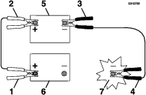
      g012785
    4. Connect the other end of the positive cable to the positive terminal of the booster battery.

    5. Connect the black negative (–) cable to the other terminal (negative) of the booster battery.

    6. MAKE THE FINAL CONNECTION ON THE ENGINE BLOCK OF THE STALLED VEHICLE (NOT TO THE NEGATIVE POST) AWAY FROM THE BATTERY. STAND BACK.

    7. Start the vehicle and remove the cables in the reverse order of connection (the engine block (black) connection is the first to disconnect).

    Check Tines

    Maintenance Service IntervalMaintenance Procedure
    Before each use or daily
  • Check for damaged or missing tines.
    1. Stop engine, wait for all moving parts to stop, and remove key. Engage parking brake.

    2. Remove rocks and other debris from the tines.

    3. Check for damaged or missing tines and replace as required.

    Check for Loose Hardware

    Maintenance Service IntervalMaintenance Procedure
    Before each use or daily
  • Check for loose hardware.
    1. Stop engine, wait for all moving parts to stop, and remove key. Engage parking brake.

    2. Visually inspect machine for any loose hardware or any other possible problem. Tighten hardware or correct the problem before operating.

    Service Air Cleaner

    Maintenance Service IntervalMaintenance Procedure
    Every 250 hours
  • Replace the primary air cleaner element — check secondary air cleaner element; replace if dirty.(May need more often under severe conditions. See the Engine manual for additional information.)
  • Every 500 hours
  • Replace the secondary air cleaner element.(May need more often under severe conditions. See the Engine manual for additional information.)
    1. Stop engine, wait for all moving parts to stop, and remove key. Engage parking brake.

    2. See the Engine Owner's Manual for maintenance instructions.

    Change Engine Oil

    Maintenance Service IntervalMaintenance Procedure
    After the first 5 hours
  • Change the engine oil.
  • Every 100 hours
  • Change the engine oil.
    1. Stop engine, wait for all moving parts to stop, and remove key. Engage parking brake.

    2. Drain oil while engine is warm from operation.

    3. The oil drain hose assembly is located towards the rear of the machine.

      Place pan under machine to catch oil. Remove oil drain plug. Allow oil to drain and replace oil drain plug. Torque plug to 20-24 ft-lb (27-33 N-m).

    4. Replace the oil filter per the Engine Owner's Manual. Clean around the oil filter and carefully remove the filter by unscrewing it. Make sure no oil drains onto the belt drives through the holes in the engine deck. Before the new filter is installed, apply a thin coating of Exmark 4–Cycle Premium Engine Oil on the surface of the rubber seal. Turn filter clockwise until rubber seal contacts the filter adapter, then tighten filter an additional 2/3 to 3/4 turn.

    5. Clean around oil fill cap and remove cap. Fill to specified capacity and replace cap.

    6. Use oil recommended in the Check Engine Oil Level section. Do Not overfill. Start the engine and check for leaks. Stop engine and recheck oil level.

    7. Wipe up any spilled oil from engine deck mounting surfaces.

    Check Hydraulic Oil and Reservoir Level

    Maintenance Service IntervalMaintenance Procedure
    Every 50 hours
  • Check the hydraulic and reservoir oil level.
    1. Lower the tines to the ground.

    2. Stop engine and wait for all moving parts to stop, and remove key. Engage parking brake.

    3. Clean area around hydraulic reservoir cap and remove cap. Oil level should be halfway up the sight window on the right side of the reservoir. If not, add oil. Use Exmark Premium Hydro oil. Replace hydraulic reservoir cap and tighten until snug. Do Not overtighten.

      Note: The oil level varies with the temperature of the oil. If the oil is at room temperature (about 75°F (24°C)), fill only to the middle of the sight window.

    Check Tire Pressures

    Maintenance Service IntervalMaintenance Procedure
    Every 50 hours
  • Check the tire pressures.
    1. Stop engine, wait for all moving parts to stop, and remove key. Engage parking brake.

    2. Check tire pressure in drive tires.

    3. Inflate drive tires to 16-20 psi (110-138 kPa).

    Check Condition and Tension Of Belts

    Maintenance Service IntervalMaintenance Procedure
    Every 50 hours
  • Check the condition and tension of the belts.
    1. Stop engine, wait for all moving parts to stop, and remove key. Engage parking brake.

    2. Lift the front of the unit and support using jack stands or equivalent support.

    3. Check condition of the hydro pump drive belt.

    Lubricate Grease Fittings

    Maintenance Service IntervalMaintenance Procedure
    Every 25 hours
  • Grease tine shaft bearings.
  • Every 50 hours
  • Grease cylinder lift.
  • Yearly
  • Grease the front caster pivots.
  • Grease belt idler pivot.
  • Note: See chart for service intervals.

    1. Stop engine, wait for all moving parts to stop, and remove key. Engage parking brake.

    2. Lubricate fittings with NLGI grade #2 multi-purpose gun grease.

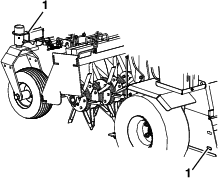
      Refer to the following chart for fitting locations and lubrication schedule.

      Lubrication Chart

      Fitting LocationsInitial Pumps Number of Places Service Interval
      1. Front Caster Pivots*04Yearly
      2. Tine Shaft Bearings1425 hours
      3. Belt Idler Pivot11Yearly
      4. Cylinder Lift1250 hours
      Graphic

      *See step 3 for special lubrication instructions on the front caster pivots.

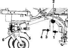
    3. Lubricate front caster pivots once a year. Remove hex plug and cap. Thread grease zerk in hole and pump with grease until it oozes out around top bearing. Remove grease zerk and thread plug back in. Place cap back on.

    Check Spark Plug

    Maintenance Service IntervalMaintenance Procedure
    Every 160 hours
  • Check the spark plug.
  • Remove the spark plug, check condition and reset gaps, or replace with a new plug. See Engine Owner's Manual.

    Change Fuel Filter

    A fuel filter is installed in the fuel line between the fuel tank and the engine. Replace when necessary.

    Note: It is important to reinstall the fuel line hoses and secure in place, the same way as originally installed at the factory, to keep the fuel line away from components.

    Change Hydraulic Filters and Fluid

    Maintenance Service IntervalMaintenance Procedure
    After the first 100 hours
  • Change hydraulic system filter and fluid
  • Every 500 hours
  • Change hydraulic system filter and fluid (Every 250 hours/Yearly if using Mobil 1 15W50)thereafter (Every 250 hours/Yearly if using Mobil 1 15W-50 thereafter)
    1. Stop engine, wait for all moving parts to stop, and remove key or spark plug wire(s). Engage parking brake.

    2. Place a catch pan below the hydros and allow oil to drain from the reservoir.

    3. Carefully clean area around filter. It is important that no dirt or contamination enter hydraulic system.

    4. Unscrew filter to remove and allow oil to finish draining from drive system.

      Important: Before reinstalling new filters, apply a thin coat of Premium Hydro Oil on the surface of the filters rubber seal.

      Turn the filters clockwise until rubber seal contacts the filter adapter then tighten the filter an additional 3/4 to 1 full turn.

    5. Reinstall the drain plug.

    6. Fill the hydraulic reservoir until fluid is halfway up the sight window.

      Exmark Premium Hydro Oil is recommended. Refer to the chart for an acceptable alternative:

      Hydro OilService Interval
      Exmark Premium Hydro OilAfter first 250 hours *Every 500 hours thereafter
      Mobil 1 15W-50 After first 250 hours *Every 250 hours thereafter

      *May need more often under severe conditions.

    7. Raise the rear of machine up and support with jack stands (or equivalent support) just high enough to allow drive wheels to turn freely.

    8. Start engine and move throttle control ahead to 1/2 throttle position. Disengage parking brake.

      1. With the engine running, slowly move the directional control in both forward and reverse directions (5 to 6 times). Check the oil level, and add oil as required after stopping the engine.

      2. It may be necessary to repeat step 1. until all the air is completely purged from the system. When the transaxle operates at normal noise levels and moves smoothly forward and reverse at normal speeds, then the transaxle is considered purged.

    Note: Do Not change the hydraulic system oil (except for what can be drained when changing filter and removing the drain plugs), unless it is felt the oil has been contaminated or been extremely hot.

    Changing oil unnecessarily could damage hydraulic system by introducing contaminants into the system.

    Check Wheel Motor Output Shaft Nut Torque Specification

    Maintenance Service IntervalMaintenance Procedure
    After the first 5 hours
  • Check the wheel motor output shaft nut torque specification.
  • Yearly
  • Check the wheel motor output shaft nut torque specification.thereafter
  • Torque the nut on the wheel motor output tapered shaft to 211-260 ft-lb (286-352 N-m).

    Check Wheel Lug Nuts Torque Specification

    Maintenance Service IntervalMaintenance Procedure
    Yearly
  • Check the wheel lug nuts torque specification.
  • Torque the wheel lug nuts to 90-95 ft-lb (122-129 N-m).

    Check Spark Arrester

    Maintenance Service IntervalMaintenance Procedure
    Every 50 hours
  • Check spark arrester (if equipped).
  • Warning

    Hot exhaust system components may ignite gasoline vapors even after the engine is stopped. Hot particles exhausted during engine operation may ignite flammable materials. Fire may result in personal injury or property damage.

    Do Not refuel or run engine unless spark arrester is installed.

    1. Stop engine, wait for all moving parts to stop, and remove key. Engage parking brake.

    2. Wait for muffler to cool.

    3. If any breaks in the screen or welds are observed, replace arrester.

    4. If plugging of the screen is observed, remove arrester and shake loose particles out of the arrester and clean screen with a wire brush (soak in solvent if necessary). Reinstall arrester on exhaust outlet.

    Thread Locking Adhesives

    Thread locking adhesives such as “Loctite 242” or “Fel-Pro, Pro-Lock Nut Type” are used on the following fasteners:

    All set screws.

    Adjustments

    Note: Shut off engine, wait for all moving parts to stop, engage parking brake, and remove key before servicing, cleaning, or making any adjustments to the unit.

    Transmission Drive Belt Tension

    Note: No adjustments are required for belt tension.

    1. Stop engine, wait for all moving parts to stop, and remove key. Engage parking brake.

    2. Install the new belt.

    3. Make sure the idler arm and pulley can move freely.

    Motion Control Linkage Adjustment

    1. Park the machine on a level surface.

    2. Shut off engine and wait for all moving parts to stop.

    3. Push the control levers all the way forward to the front reference bar.

      • If the control levers contact the reference bar, allow the control levers to return to neutral. Remove the quick attach rod end on the bottom of the motion control linkage. Rotate the rod end counterclockwise (as viewed from the top of the machine). Reinstall the rod end quick attach and move the control lever forward. Repeat this step until there is a gap between the control lever and the front reference bar. Once the gap is achieved, proceed with step 4.
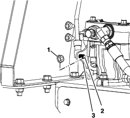
        g310417

      • If the control levers do not contact the reference bar, then proceed to step4.

    4. Allow the control levers to return to neutral. Remove the quick attach rod end on the bottom of the motion control linkage. Rotate the turnbuckle clockwise (as viewed from the top of the machine). Reinstall the rod end and move the control lever forward. Repeat this step until there is minimal gap or contact between the control lever and the front reference bar.

    5. Remove the rod end quick attach, rotate the rod end clockwise one more full turn.

    6. Reinstall the rod end.

    7. Repeat steps 3 through 6 for other motion control linkage.

    Cleaning

    Cleaning and Storing Safety

    • Park machine on level ground, disengage drives, set parking brake, stop engine, and remove key. Wait for all moving parts to stop before leaving the operator’s position. Allow the machine to cool before servicing, adjusting, fueling, unclogging, cleaning, or storing.

    • Clean grass and debris from the muffler, drives, and engine compartment to prevent fires.

    • Allow the machine to cool before storing the machine in any enclosure. Do Not store the machine or fuel container, or refuel, where there is an open flame, spark, or pilot light such as on a water heater or other appliance.

    Clean Engine and Exhaust System Area

    Maintenance Service IntervalMaintenance Procedure
    Before each use or daily
  • Clean the engine and exhaust system area.(May be required more often in dry or dirty conditions.)
  • Caution

    Excessive debris around engine cooling air intake and exhaust system area can cause engine, exhaust area, and hydraulic system to overheat which can create a fire hazard.

    Clean all debris from engine and exhaust system area.

    1. Stop engine, wait for all moving parts to stop, and remove key. Engage parking brake.

    2. Clean all debris from rotating engine air intake screen, around engine shrouding, and exhaust system area.

    3. Wipe up any excessive grease or oil around the engine and exhaust system area.

    Remove Engine Shrouds and Clean Cooling Fins

    Maintenance Service IntervalMaintenance Procedure
    Every 80 hours
  • Remove engine shrouds and clean cooling fins.
    1. Stop engine, wait for all moving parts to stop, and remove key. Engage parking brake.

    2. Remove cooling shrouds from engine and clean cooling fins. Also clean dust, dirt, and oil from external surfaces of engine which can cause improper cooling.

    3. Make sure cooling shrouds are properly reinstalled. Operating the engine without cooling shrouds will cause engine damage due to overheating.

    Clean Debris From Machine

    Maintenance Service IntervalMaintenance Procedure
    Before each use or daily
  • Clean the grass and debris build-up from the machine.
    1. Stop engine, wait for all moving parts to stop, and remove key. Engage parking brake.

    2. Clean off any oil, debris, or grass build-up on the machine and aerator deck, especially under chain guards, around the fuel tank, around engine and exhaust area.

      Important: You can wash the machine with mild detergent and water. Do not pressure wash the machine. Avoid excessive use of water, especially near the control panel, around the engine, hydraulic pumps, and motors.

    Waste Disposal

    Motor Oil Disposal

    Engine oil and hydraulic oil are both pollutants to the environment. Dispose of used oil at a certified recycling center or according to your state and local regulations.

    Battery Disposal

    Danger

    Battery electrolyte contains sulfuric acid, which is poisonous and can cause severe burns. Swallowing electrolyte can be fatal or if it touches skin can cause severe burns.

    • Wear safety glasses to shield eyes, and rubber gloves to protect skin and clothing when handling electrolyte.

    • Do Not swallow electrolyte.

    • In the event of an accident, flush with water and call a doctor immediately.

    Federal law states that batteries should not be placed in the garbage. Management and disposal practices must be within relevant federal, state, or local laws.

    If a battery is being replaced or if the unit containing the battery is no longer operating and is being scrapped, take the battery to a local certified recycling center. If no local recycling is available return the battery to any certified battery reseller.
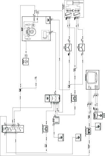
    Troubleshooting

    Important: It is essential that all operator safety mechanisms be connected and in proper operating condition prior to use.

    When a problem occurs, do not overlook the simple causes. For example: starting problems could be caused by an empty fuel tank.

    The following table lists some of the common causes of trouble. Do Not attempt to service or replace major items or any items that call for special timing of adjustments procedures (such as valves, governor, etc.). Have this work done by your Engine Service Dealer.

    Note: When disconnecting electrical connectors Do Not pull on the wires to separate the connectors.

    ProblemPossible CauseCorrective Action
    Starter does not crank.
    1. Battery does not have a full charge.
    2. Electrical connections are corroded, loose or faulty.
    3. Fuse is blown.
    4. Relay or switch is defective.
    1. Charge the battery. See Check Battery Charge and Recommended Jump Starting Procedure sections in Maintenance.
    2. Check the electrical connections for good contact. Clean connector terminals thoroughly with electrical contact cleaner, apply dielectric grease and reconnect.
    3. Replace the blown fuse.
    4. Contact an Authorized Service Dealer.
    Engine will not start, starts hard, or fails to keep running
    1. Fuel tank is empty.
    2. The throttle and choke are not in the correct position.
    3. Dirt in fuel filter.
    4. Dirt, water, or stale fuel is in the fuel system.
    5. Air cleaner is dirty.
    6. Electrical connections are corroded, loose or faulty.
    7. Relay or switch is defective.
    8. Faulty spark plug.
    9. Spark plug wire is not connected.
    1. Fill the fuel tank.
    2. Be sure the throttle control is midway between the “SLOW” and “FAST” positions, and the choke is in the “ON” position for a cold engine or the “OFF” position for a warm engine.
    3. Replace the fuel filter.
    4. Contact an Authorized Service Dealer.
    5. Clean or replace the air cleaner element.
    6. Check the electrical connections for good contact. Clean connector terminals thoroughly with electrical contact cleaner, apply dielectric grease and reconnect.
    7. Contact an Authorized Service Dealer.
    8. Clean, adjust or replace spark plug.
    9. Check the spark plug wire connection.
    Engine loses power.
    1. Engine load is excessive.
    2. Air cleaner is dirty.
    3. Oil level in the crankcase is low.
    4. Cooling fins and air passages for the engine are plugged.
    5. Dirt in fuel filter.
    6. Dirt, water, or stale fuel is in the fuel system.
    1. Reduce the ground speed or aeration depth.
    2. Clean or replace the air cleaner element.
    3. Add oil to the crankcase.
    4. Remove the obstructions from the cooling fins and air passages.
    5. Replace the fuel filter.
    6. Contact an Authorized Service Dealer.
    Engine overheats.
    1. Engine load is excessive.
    2. Oil level in the crankcase is low.
    3. Cooling fins and air passages for the engine are plugged.
    1. Reduce the ground speed or aeration depth.
    2. Add oil to the crankcase.
    3. Remove the obstructions from the cooling fins and air passages.
    Machine pulls left or right (with levers fully forward).
    1. Tire pressure in drive tires not correct.
    2. Tracking needs adjustment.
    3. Drive wheel release valves are open.
    1. Adjust tire pressure in the drive tires.
    2. See Motion Control Linkage Adjustment in Adjustments section.
    3. Close drive wheel release valves.
    Machine does not drive.
    1. Drive or pump belt is worn, loose or broken.
    2. Drive or pump belt is off a pulley.
    1. Change the belt.
    2. Change the belt.
    Abnormal vibration.
    1. Tine(s) is/are bent.
    2. Tine mounting bolt is loose.
    3. Engine mounting bolts are loose.
    4. Loose engine pulley or idler pulley.
    5. Engine pulley is damaged.
    6. Belt is damaged.
    1. Install new tine(s).
    2. Tighten the tine mounting bolt.
    3. Tighten the engine mounting bolts.
    4. Tighten the appropriate pulley.
    5. Contact an Authorized Service Dealer.
    6. Install new belt.
    Tines do not raise.
    1. Short in harness.
    2. Hydraulic oil reservoir is low on oil.
    1. Contact an Authorized Service Dealer.
    2. Add oil to reservoir.
    Tines do not engage the ground.
    1. Pump belt problem.
    2. Harness/switch is damaged.
    3. Hydraulic oil reservoir is low on oil.
    4. Cylinder stop is in place.
    1. Tension or replace belt.
    2. Contact an Authorized Service Dealer.
    3. Add oil to reservoir.
    4. Remove cylinder stop, clevis pin and hair pin.

    Schematics

    Electrical Schematic

    g317546