| Maintenance Service Interval | Maintenance Procedure |
|---|---|
| Before each use or daily |
|
Introduction
This machine is a ride-on, reel-blade greens mower intended to be used by professional, hired operators in commercial applications. It is primarily designed for cutting grass on well-maintained turf. Using this product for purposes other than its intended use could prove dangerous to you and bystanders.
Read this information carefully to learn how to operate and maintain your product properly and to avoid injury and product damage. You are responsible for operating the product properly and safely.
Visit www.Toro.com for more information, including safety tips, training materials, accessory information, help finding a dealer, or to register your product.
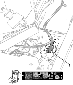
Whenever you need service, genuine Toro parts, or additional information, contact an authorized Toro distributor and have the model and serial numbers of your product ready. Figure 1 identifies the location of the model and serial numbers on the product. Write the numbers in the space provided.
Important: With your mobile device, you can scan the QR code on the serial number decal (if equipped) to access warranty, parts, and other product information.
This manual identifies potential hazards and has safety messages identified by the safety-alert symbol (Figure 2), which signals a hazard that may cause serious injury or death if you do not follow the recommended precautions.

This manual uses 2 words to highlight information. Important calls attention to special mechanical, electrical, or diagnostic information and Note emphasizes general information worthy of special attention.
This product complies with all relevant European directives; for details, please see the separate product specific Declaration of Conformity (DOC) sheet.
It is a violation of California Public Resource Code Section 4442 or 4443 to use or operate the engine on any forest-covered, brush-covered, or grass-covered land unless the engine is equipped with a spark arrester, as defined in Section 4442, maintained in effective working order or the engine is constructed, equipped, and maintained for the prevention of fire.
The enclosed engine owner's manual is supplied for information regarding the US Environmental Protection Agency (EPA) and the California Emission Control Regulation of emission systems, maintenance, and warranty. Replacements may be ordered through the engine manufacturer.
Operating this machine 1,000 m (3,280 ft) above sea level requires a high-altitude jet. Refer to your Kawasaki engine owner’s manual for more information.
Warning
CALIFORNIA
Proposition 65 Warning
The engine exhaust from this product contains chemicals known to the State of California to cause cancer, birth defects, or other reproductive harm.
Battery posts, terminals, and related accessories contain lead and lead compounds, chemicals known to the State of California to cause cancer and reproductive harm. Wash hands after handling.
Use of this product may cause exposure to chemicals known to the State of California to cause cancer, birth defects, or other reproductive harm.
Safety
This machine has been designed in accordance with EN ISO 5395 and ANSI B71.4-2017 and meets these standards when you complete the setup procedures.
General Safety
This product is capable of amputating hands and feet and of throwing objects.
-
Read and understand the contents of this Operator’s Manual before starting the engine.
-
Use your full attention while operating the machine. Do not engage in any activity that causes distractions; otherwise, injury or property damage may occur.
-
Do not put your hands or feet near moving components of the machine.
-
Do not operate the machine without all guards and other safety protective devices in place and functioning properly on the machine.
-
Keep bystanders and children out of the operating area. Never allow children to operate the machine.
-
Shut off the machine, remove the key, and wait for all movement to stop before you leave the operator’s position. Allow the machine to cool before adjusting, servicing, cleaning, or storing it.
Improperly using or maintaining this machine can result in injury.
To reduce the potential for injury, comply with these safety instructions
and always pay attention to the safety-alert symbol  , which means
Caution, Warning, or Danger—personal safety instruction. Failure
to comply with these instructions may result in personal injury or
death.
, which means
Caution, Warning, or Danger—personal safety instruction. Failure
to comply with these instructions may result in personal injury or
death.
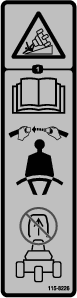
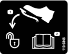
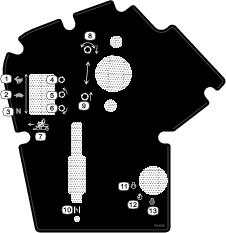
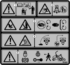
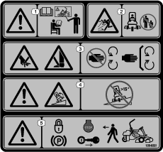
Safety and Instructional Decals
|
Safety decals and instructions are easily visible to the operator and are located near any area of potential danger. Replace any decal that is damaged or missing. |


Setup
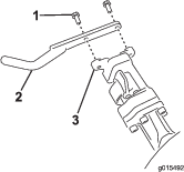
Installing the Roll Bar
Parts needed for this procedure:
| Roll bar assembly | 1 |
| Hex-head bolt (3/8 x 1-1/2 inch) | 8 |
| Nut (3/8 inch) | 8 |
-
Remove the top support from the crate.
-
Remove the roll bar from the crate.
-
Use 8 hex-head bolts (3/8 x 1-1/2 inch) and 8 nuts (3/8 inch) to secure the roll bar to the roll-bar brackets on each side of the machine (Figure 3).
Note: Have an assistant help you to position and secure the roll bar to the machine.
-
Torque the fasteners to 51 to 65 N∙m (38 to 48 ft-lb).
Installing the Seat
Parts needed for this procedure:
| Seat Kit (order separately; contact your authorized Toro distributor) | 1 |
Acquire the Seat Kit (contact your authorized Toro distributor) and refer to the kit Installation Instructions to install the seat.
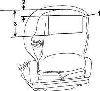
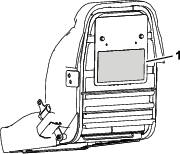
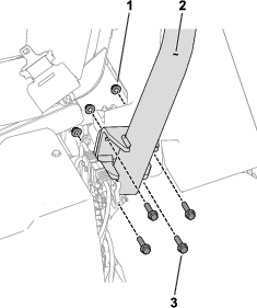
Installing the Service Decal
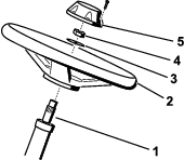
Installing the Steering Wheel
Parts needed for this procedure:
| Steering wheel | 1 |
| Cap | 1 |
| Washer | 1 |
| Locknut | 1 |
Connecting the 12V Battery
Parts needed for this procedure:
| Screw (M5) | 2 |
| Nut (M5) | 2 |
Warning
Incorrect battery cable routing could damage the machine and cables causing sparks. Sparks can cause the battery gasses to explode, resulting in personal injury.
Always connect the positive (red) battery cable before connecting the negative (black) cable.
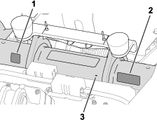
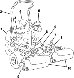
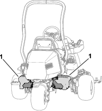
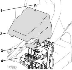
The 12V battery is below the operator’s seat on the right side of the machine (Figure 7).
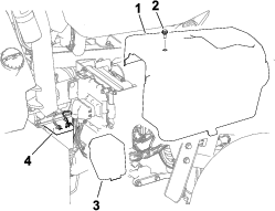
-
Remove the right side cover
-
Remove the battery cover to access the battery.
-
Use a M5 screw and nut to connect the positive (red) battery cable to the positive (+) terminal.
-
Use a M5 screw and nut to connect the negative (black) battery cable to the negative (-) terminal.
-
Torque the screws and nuts on the terminals to 3 to 4 N∙m (34 to 37 in-lbs).
-
Apply battery terminal protector (Toro Part No. 107-0392) or a light layer of grease to the battery terminals and cable connectors to reduce corrosion.
-
Install the cover over the battery.
-
Install the right side cover.
Installing the Grass-Basket Hooks
Parts needed for this procedure:
| Grass-basket hook | 6 |
| Flange bolts | 12 |
Use 12 flange bolts to install 6 grass-basket hooks onto the ends of the suspension-arm bars (Figure 8).
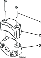
Installing the Cutting Units
Parts needed for this procedure:
| Cutting unit (order separately; contact your authorized Toro distributor) | 3 |
| Grass basket | 3 |
| Electric counterweight | 3 |
| Capscrew | 6 |
| O-ring | 3 |
-
Prepare the cutting units for installation; refer to your cutting unit Operator’s Manual.
-
Apply grease to the inside spline of the drive coupler.
-
Install an O-ring to each reel motor as shown in Figure 9.
-
Secure the electrical counterweight to the existing counterweight with 2 capscrews as shown in Figure 10.
-
Install the cutting units; refer to Installing the Cutting Units.
-
Install each grass basket onto the grass-basket hooks.
Adjusting the Machine Settings
-
Connect the main-power connectors; refer to Main-Power Connectors.
-
Use the InfoCenter to adjust the machine settings; refer to Using the InfoCenter to Adjust the Machine Settings.
Installing the CE Decals
If Required (CE-Compliant Countries)
Parts needed for this procedure:
| Production year decal | 1 |
| CE warning decal (Part No. 139-8321) | 1 |
| CE mark decal (Part No. 93-7252) | 1 |
If you use this machine in a country that complies to CE standards, install the following decals:
Reducing the Tire Pressure
The tires are overinflated at the factory for shipping purposes. Reduce the pressure to the proper levels before starting the machine; refer to Checking the Tire Pressure.
Product Overview
Key Switch
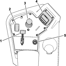
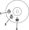
The key switch has 3 positions: OFF, ON, and START (Figure 15).
Use the key switch to start the engine, shut off the engine, or drive the machine without engine power; refer to Starting the Engine,Shutting Off the Engine, and Driving the Machine Without Engine Power.
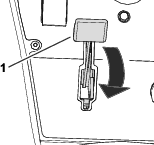
Choke Lever
To start a cold engine, close the carburetor choke by pushing the choke lever (Figure 14) forward to the CLOSED position. After the engine starts, regulate the choke lever to keep the engine running smoothly. As soon as possible, open the choke by pulling the lever rearward (Figure 14) to the OPEN position. A warm engine requires little or no choking.
Function-Control Switch
The function-control switch (Figure 14) provides 2 traction selections plus a NEUTRAL position.
-
NEUTRAL position—neutral and backlapping
-
MOW position—used for mowing operation
-
TRANSPORT position—used for transport operation
You can shift from MOW to TRANSPORT or TRANSPORT to MOW (not to NEUTRAL) while the machine is in motion; no damage will result
You can move the switch from TRANSPORT or MOW to NEUTRAL and the machine will come to a stop. If you try to switch from NEUTRAL to MOW or TRANSPORT while the pedal is not in the NEUTRAL position, an advisory occurs.
Lift/Lower Joystick
The lift/lower joystick (Figure 14) raises or lowers the cutting units. The joystick can engage or disengage the cutting-unit reels, depending on the function-control-switch position:
-
Function-control switch in the NEUTRAL position: The cutting units will raise or lower as long as you move the joystick forward or backward, but the reels will not engage unless the machine is in Backlap Mode.
-
Function-control switch in the MOW position: Move the joystick forward during your cutting operation to lower the cutting units and start the reels. Pull back on the joystick to stop the reels and raise the cutting units.
To stop the reels without raising the cutting units, pull back on the joystick momentarily and release it. Moving the joystick forward again will start the reels or pulling back again will lift the cutting units. You must engage this feature in the InfoCenter; refer to Adjusting the Tap-Off Delay.
-
Function-control switch in the TRANSPORT position: The cutting units can be raised, but the reels will not engage. An advisory appears in the InfoCenter if you attempt to lower the cutting units.
Traction Pedal
The traction pedal (Figure 17) has 3 functions: to make the machine move forward, to move it backward, and to stop the machine. Press the top of the pedal to move forward; press the bottom to move backward or to assist in stopping when moving forward.
To stop the machine, allow the pedal to move to the NEUTRAL position. Do not rest the heel of your foot on the traction pedal in the REVERSE position while the machine is moving forward (Figure 18).

You can configure the maximum ground speed as follows:
-
3.2 to 8 km/h (3 to 5 mph) forward mowing speed
-
8 to 16 km/h (5 to 10 mph) transport speed
-
3.2 to 4.8 km/h (2 to 3 mph) reverse speed
Steering-Arm-Locking Pedal
Press the pedal (Figure 17) and raise or lower the steering arm for operator comfort, then, release the pedal to lock the arm in place.
Brake Pedal
Press the brake pedal (Figure 19) to stop the machine.
Parking Brake
Use the parking brake (Figure 19) to prevent the machine from moving. To engage the parking brake, push down on the brake pedal and press the top forward to latch. To release the parking brake, press the brake pedal until the parking-brake latch retracts.
InfoCenter
Using the InfoCenter LCD Display
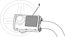
The InfoCenter LCD display shows information about your machine, such as the operating status, various diagnostics, and other information about the machine (Figure 23). There is a splash screen, main information screen, cutting unit (CU) motor information screen, and traction information screen.
-
Splash screen: shows current machine information for a few seconds after you move the key to the ON position.
-
Main information screen (Figure 20): shows current machine information while the key is in the ON position.

-
CU motor information screen
 (Figure 21): shows the speed and current
of each reel motor.
(Figure 21): shows the speed and current
of each reel motor.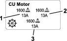
-
Traction information screen
(Figure 22): shows the current steering
angle and the amperage allotted to each traction motor.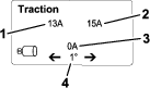
-
Main menu: refer to Understanding the InfoCenter Menu Items.
Note: Protected
under Protected Menus—accessible only by entering PIN; refer
to Accessing Protected Menus.
You can switch between the main, CU motor, and traction information screens by pressing the right button and then selecting the appropriate directional arrow.
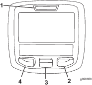
-
Left Button, Menu Access/Back Button—Press this button to access the InfoCenter menus. You can use it to back out of any menu you are currently using.
-
Middle Button—Use this button to scroll down menus.
-
Right Button—Use this button to open a menu where a right arrow indicates additional content, or to select an option.
Note: The purpose of each button may change depending on what is required at the time. Each button will be labeled with an icon displaying its current function.
| SERVICE DUE | Indicates when scheduled service should be performed |
 | Engine rpm/status—indicates the engine speed (rpm) |
 | Hour meter |
 | Info icon |
 | Function-control switch is in the TRANSPORT position. |
 | Function-control switch is in the MOW position. |
 | Indicates when the cutting units are being raised. |
 | Indicates when the cutting units are being lowered. |
 | Operator must sit in seat |
 | Parking-brake indicator—indicates when the parking brake is engaged |
 | Function-control switch is in the NEUTRAL position. |
 | PTO is engaged |
 | Engine start |
 | Stop or shutdown |
 | Engine |
 | Key switch |
 | PIN code |
 | CAN bus |
 | InfoCenter |
 | Switch |
 | Operator must release switch |
 | Operator should change to indicated state |
 | Traction motor |
 | Return to previous screen |
 | Item not selected/active |
 | Item selected/active |
 | Reel |
 | Electric-parking-brake indicator—indicates when the electric parking brake is engaged |
| Symbols are often combined to form sentences. Some examples are shown below: | |
 | Operator should put the machine in neutral |
 | Engine start denied |
 | Engine shutdown |
 | Sit down or engage the parking brake |
Understanding the InfoCenter Menu Items
To access the main menu, press any button while at the main,
CU motor, or traction information screen, then press the button that
corresponds with the symbol. This brings you to the MAIN
MENU.
Refer to the following tables for a description of the options available from the menus:
| Menu Item | Description |
| FAULTS | The FAULTS menu contains a list of the recent machine faults. Refer to the Service Manual or your authorized Toro distributor for more information on the FAULTS menu. |
| SERVICE | The SERVICE menu contains information on the machine such as hours of use, counts, and calibration. You can also enable the cutting-unit backlap procedure. Refer to the Service table. |
| DIAGNOSTICS | The DIAGNOSTICS menu lists various states and data that the machine currently has. You can use this information to troubleshoot certain issues, as it quickly tells you which machine controls are on/off and lists control levels (e.g., sensor values). |
| SETTINGS | The SETTINGS menu allows you to customize and modify configuration variables on the InfoCenter display. Refer to the Settings table. |
| ABOUT | The ABOUT menu lists the model number, serial number, and software version of your machine. Refer to the About table. |
| Menu Item | Description |
| CURRENT | Lists the total number of key-on hours (i.e., hours that the key has been in the ON position). |
| LAST | Indicates the last key-on hour that the fault occurred on. |
| FIRST | Indicates the first key-on hour that the fault occurred on. |
| OCCURRENCES | Indicates the number of fault occurrences. |
| Menu Item | Description |
| HOURS | Lists the total number of hours that the key, engine, reels, and backlap have been on, as well as the next service due. |
| COUNTS | Lists the number of starts, mows, tap-offs, backlaps, and number of times that the engine was cranked longer than 30 seconds. |
| BACKLAP | Engages/disengages the cutting-unit backlap procedure (when you engage this procedure, you can disengage the mode with this setting or by moving the key to the OFF position). |
| CALIBRATION | Allows you to calibrate the steering system, traction system, and lift actuators. Refer to the Service Manual for more information on calibration. |
| Menu Item | Description |
| UNITS | Controls the units used on the InfoCenter. The menu choices are English or metric. |
| LANGUAGE | Controls the language used on the InfoCenter. |
| BACKLIGHT | Controls the brightness of the LCD display. |
| CONTRAST | Controls the contrast of the LCD display. |
| PROTECTED MENUS | Allows you to access protected menus by inputting a passcode. |
| PROTECT SETTINGS | Controls the protected menus. |
| RESET DEFAULTS | Resets the InfoCenter to default settings. |
| TAPOFF TIME | Controls the tap-off delay. |
| REEL SPEED | Controls the reel speed. |
| LOWER SPEED | Sets the speed that the cutting units lower to the ground for mowing. |
| BACKLAP RPM | Controls the backlap rpm speed. |
| CLIP CONTROL | Turns the automatic clip-control feature ON/OFF. |
| BLADE COUNT | Set the number of blades in each reel. This setting is only necessary if CLIP CONTROL is set to ON. |
| HEIGHT OF CUT (HOC) | Sets the desired height of cut. This setting is only necessary if CLIP CONTROL is set to ON. |
| MAX MOW | Sets the maximum machine speed while mowing. |
| MAX TRANSPORT | Sets the maximum machine speed while transporting. |
| MAX REVERSE | Sets the maximum machine speed while moving the machine in reverse. |
| SLOW & TURN | Enables or disables the slow in turn function. |
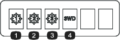
| 3WD KIT | Enables or disables the 3-Wheel Drive Kit. |
| Menu Item | Description |
| MODEL | Lists the model number of the machine. |
| SN | Lists the serial number of the machine. |
| S/W Rev | Lists the software revision of the master controller. |
| INFOCENTER | Lists the software revision of the InfoCenter. |
| CU1 | Lists the software revision of the center cutting unit motor . |
| CU2 | Lists the software revision of the front, left cutting unit motor. |
| CU3 | List the software revision of the front, right cutting unit motor. |
| GENERATOR | Lists the serial number of the generator. |
| LL1 | Lists the software part number and the revision version for the center cutting unit. |
| LL2 | Lists the software part number and the revision version for the front left cutting unit. |
| LL3 | Lists the software part number and the revision version for the front right cutting unit. |
| TRACTION1 | Lists the software part number and the revision version for the front right traction motor. |
| TRACTION2 | Lists the software part number and the revision version for the front left traction motor. |
| STEERING | Lists the software part number and the revision version for the rear steering motor. |
| CAN BUS | Lists the machine communication bus status. |
| TRACTION3 | Lists the software part number and the revision version for the 3-Wheel Drive Kit (if equipped). |
Note: Protected
under Protected Menus—accessible only by entering PIN; refer
to Accessing Protected Menus.
Accessing Protected Menus
Note: The factory default PIN code for you machine is either 0000 or 1234.If you changed the PIN code and forgot the code, contact your authorized Toro distributor for assistance.
-
From the MAIN MENU, use the center button to scroll down to the SETTINGS MENU and press the right button.
-
In the SETTINGS MENU, use the center button to scroll down to the PROTECTED MENU and press the right button.
-
To enter the PIN code, press the center button until the correct first digit appears, then press the right button to move on to the next digit. Repeat this step until the last digit is entered and press the right button once more.
-
Press the middle button to enter the PIN code.
Wait until the red indicator light of the InfoCenter illuminates.
Note: If the InfoCenter accepts the PIN code and the protected menu is unlocked, the word “PIN” displays in the upper right corner of the screen.
You have the ability to view and change the settings in the Protected Menu. Once you access the Protected Menu, scroll down to the Protect Settings option. Use the right button to change the setting.
-
Setting the Protect Settings to OFF allows you to view and change the settings in the Protected Menu and view the CU motor and traction information screens without entering the PIN code.
-
Setting the Protect Settings to ON hides the protected options and requires you to enter the PIN code to change the setting in the Protected Menu.
After you set the PIN code, rotate the key switch to the OFF position and back to the ON position to enable and save this feature.
Note: Rotate the key switch to the OFF position and then to the ON position to lock the protected menu.
Setting the Machine Configuration Passcode
You can set a passcode on the InfoCenter so that an operator cannot access specific InfoCenter screens without it. Refer to Understanding the InfoCenter Menu Items for the InfoCenter screens that are passcode-protected.
-
From the SETTINGS menu, select PROTECT SETTINGS.
-
Set PROTECT SETTINGS to ON.
-
When prompted, enter a 4-digit passcode.
-
Turn the ignition key to the OFF position to save the code.
Note: If you forget the user defined passcode, you can obtain a temporary passcode from your authorized Toro distributor.
Understanding the Fault-Log Indicator
If a fault occurs, a fault code appears on the InfoCenter screen and a red flashing light appears above the screen.
The fault is stored in a log entry located in the FAULTS menu, which you or your distributor can use to identify the issue that prompted the fault.
For a list of faults, refer to the Service Manual or your authorized Toro distributor.
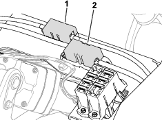
Main-Power Connectors
Before working on the machine or installing, removing, or working on the cutting units, disconnect the machine from the power supply by separating the main-power connectors (Figure 24), located at the base of the rollover bar on the left side of the traction unit. Plug the connectors together before operating the machine.
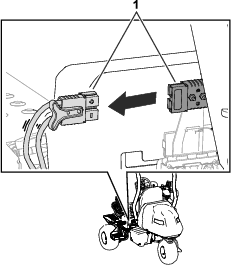
Caution
If you do not disconnect the power to the machine, someone could accidentally start the machine, causing serious bodily injury.
Always separate the connectors before working on the machine.
Fuel-Shutoff Valve
Refer to Figure 26 and the Specifications Table for dimensions and weight.
Note: Specifications and design are subject to change without notice.
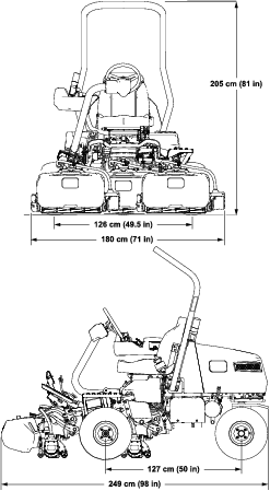
| Width of cut | 151 cm (59.5 inches) |
| Wheel track | 126 cm (49.5 inches) |
| Wheel base | 127 cm (50 inches) |
| Overall length (w/baskets) | 249 cm (98 inches) |
| Overall width | 180 cm (71 inches) |
| Overall height | 205 cm (81 inches) |
| Weight* | 737 kg (1,625 lb) |
| *Traction unit equipped with 11-blade cutting units, no fuel, no operator, and with the Standard Seat equipped. | |
Attachments/Accessories
A selection of Toro approved attachments and accessories is available for use with the machine to enhance and expand its capabilities. Contact your Authorized Service Dealer or authorized Toro distributor or go to www.Toro.com or a list of all approved attachments and accessories.
To ensure optimum performance and continued safety certification of the machine, use only genuine Toro replacement parts and accessories. Replacement parts and accessories made by other manufacturers could be dangerous, and such use could void the product warranty.
Operation
Before Operation
Before Operation Safety
General Safety
-
Never allow children or untrained people to operate or service the machine. Local regulations may restrict the age of the operator. The owner is responsible for training all operators and mechanics.
-
Become familiar with the safe operation of the equipment, operator controls, and safety signs.
-
Engage the parking brake, shut off the machine, remove the key, and wait for all movement to stop before you leave the operator’s position. Allow the machine to cool before adjusting, servicing, cleaning, or storing it.
-
Know how to stop the machine and shut off the machine quickly.
-
Check that operator-presence controls, safety switches, and safety protective devices are attached and functioning properly. Do not operate the machine unless they are functioning properly.
-
Before mowing, always inspect the machine to ensure that the cutting units are in good working condition.
-
Inspect the area where you will use the machine and remove all objects that the machine could throw.
Fuel Safety
-
Use extreme care in handling fuel. It is flammable and its vapors are explosive.
-
Extinguish all cigarettes, cigars, pipes, and other sources of ignition.
-
Use only an approved fuel container.
-
Do not remove the fuel cap or fill the fuel tank while the engine is running or hot.
-
Do not add or drain fuel in an enclosed space.
-
Do not store the machine or fuel container where there is an open flame, spark, or pilot light, such as on a water heater or other appliance.
-
If you spill fuel, do not attempt to start the engine; avoid creating any source of ignition until the fuel vapors have dissipated.
Fuel Specification
Fuel tank capacity: 18.5 L (4.9 US gallons)
Recommended Fuel: Unleaded gasoline with an octane rating of 87 or higher ((R+M)/2 rating method)
Ethanol: Gasoline with up to 10% ethanol (gasohol) or 15% MTBE (methyl tertiary butyl ether) by volume is acceptable. Ethanol and MTBE are not the same. Gasoline with 15% ethanol (E15) by volume is not approved for use.
-
Never use gasoline that contains more than 10% ethanol by volume, such as E15 (contains 15% ethanol), E20 (contains 20% ethanol), or E85 (contains up to 85% ethanol).
-
Do not use fuel that contains methanol.
-
Do not store fuel either in the fuel tank or fuel containers over the winter, unless you use a fuel stabilizer.
-
Do not add oil to gasoline.
-
For best results, use only clean, fresh (less than 30 days old) fuel.
-
Using unapproved gasoline may cause performance problems and/or engine damage, which may not be covered under the warranty.
Important: Do not use fuel additives other than a fuel stabilizer/conditioner. Do not use fuel stabilizers with an alcohol base such as ethanol, methanol, or isopropanol.
Filling the Fuel Tank
-
Engage the parking brake, shut off the engine, remove the key, and wait for all movement to stop.
-
Clean around the fuel-tank cap and remove it (Figure 27).
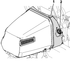
-
Add the specified fuel to the fuel tank until the level is 25 mm (1 inch) below the bottom of the filler neck. This space in the tank allows the fuel to expand.
Important: Do not fill the fuel tank completely full.
-
Install the cap.
Note: You will hear a click sound when the cap is secure.
-
Wipe up any spilled fuel.
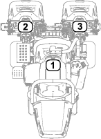
Identifying the Cutting Units
Using the InfoCenter to Adjust the Machine Settings
You can use the InfoCenter to adjust the following machine settings:
-
Tap-off delay; refer to Adjusting the Tap-Off Delay.
-
Reel speed while mowing; refer to Adjusting the Mowing Reel Speed.
-
Reel speed while backlapping the cutting units; refer to Adjusting the Backlap Reel Speed.
-
Clip control; refer to Adjusting the Clip-Control Feature.
-
Height of cut (HOC); refer to Adjusting the Height of Cut (HOC).
-
Number of cutting-unit blades; refer to Adjusting the Number of Cutting-Unit Blades.
-
Maximum mowing speed; refer to Adjusting the Maximum Mowing Speed.
-
Cutting-unit lower speed; refer to Setting the Cutting-Unit Lower Speed.
-
Maximum transport speed; refer to Adjusting the Maximum Transport Speed.
-
Maximum reverse speed; refer to Adjusting the Maximum Reverse Speed.
-
Slow in turn; refer to Setting the Slow in Turn Function.
-
Disabling an equipped 3-Wheel-Drive Kit; refer to Disabling an Equipped 3-Wheel-Drive Kit.
Note: Each setting is passcode-protected. You may need to enter a passcode to edit the settings.
Adjusting the Tap-Off Delay
Navigate to the TAPOFF TIME option to adjust the tap-off delay. The tap-off delay feature allows the cutting units to turn off without raising. The delay setting represents the maximum time for the lift/lower joystick to remain in the rearward position to activate this feature.
Refer to the following table for the delay time options and their corresponding increment numbers:
| Increment Number | Delay Time (Seconds) |
| 1 | Off |
| 2 | 0.050 |
| 3 | 0.100 |
| 4 | 0.150 |
| 5 | 0.200 |
| 6 | 0.250 |
| 7 | 0.300 |
| 8 | 0.350 |
| 9 | 0.400 |
| 10 | 0.450 |
Note: The factory default setting is 1, which disables this feature.
Adjusting the Mowing Reel Speed
Navigate to the REEL SPEED option to adjust the reel speed while mowing. This setting can be adjusted when the clip control setting is OFF; refer to Setting the Clip-Control Feature.
Refer to the following table for the reel speed options and their corresponding increment numbers:
| Increment Number | Reel Speed (RPM) |
| 1 | 800 |
| 2 | 950 |
| 3 | 1100 |
| 4 | 1250 |
| 5 | 1400 |
| 6 | 1550 |
| 7 | 1700 |
| 8 | 1850 |
| 9 | 2000 |
Note: The factory default setting is 2000 rpm (increment number 9).
Setting the Cutting-Unit Lower Speed
Navigate to the LOWER SPEED option to set the speed that the cutting units lower to the ground for mowing. You can toggle between 1 (slowest speed) and 9 (quickest speed).
Test the lower speed before you mow. Adjust the speed as desired.
Note: The factory default setting is 5.
Adjusting the Backlap Reel Speed
Navigate to the BACKLAP RPM option to adjust the reel speed while performing a backlap operation.
Refer to the following table for the reel speed options and their corresponding increment numbers:
| Increment Number | Reel Speed (RPM) |
| 1 | 200 |
| 2 | 240 |
| 3 | 280 |
| 4 | 320 |
| 5 | 360 |
| 6 | 400 |
| 7 | 440 |
| 8 | 480 |
| 9 | 520 |
Note: The factory default setting is 200 rpm (increment number 1).
Adjusting the Clip-Control Feature
Understanding the Radius-Dependent-Speed (RDS) System
To achieve a consistent, high quality-of-cut and a uniform after cut appearance, the machine is equipped with the patent-pending Radius Dependent Speed™ (RDS) system. The RDS system is a clip-control and independent wheel-speed feature that varies the speeds of each reel motor and each traction motor to maintain a constant clip and reduce turf scrubbing in turns while cutting.
When the machine is turning while cutting (e.g., during the clean-up pass), the reel on the inside of the turn will rotate at a slower rpm than the reel on the outside of the turn. The center reel splits the difference of the inside and outside reel speeds so that all three cutting units have the same clip. The sharper the turn, the greater the difference in reel speeds. Additionally, if the machine speed changes while you are cutting, the RDS system adjusts the reel speed to maintain a constant clip. This feature reduces turf thinning on the inside reel (in comparison to other riding greens mowers), which virtually eliminates triplex ring.
The RDS system also adjusts each wheel-motor speed during a turn, similar to the reel-motor speeds changing in a turn. The inside wheel motor will turn at a slower rpm than the outside wheel motor. This minimizes wheel scrubbing in the turn and can reduce triplex ring.
Setting the Clip-Control Feature
Navigate to the CLIP CONTROL option to set the RDS system feature.
-
Clip control set to ON: The machine uses your settings from the HEIGHT OF CUT (HOC) and BLADE COUNT options and the left and right wheel speeds to determine the speed of each reel.
-
Clip control set to OFF: The machine uses your setting from the REEL SPEED option.
Note: The factory default setting is ON.
Adjusting the Height of Cut (HOC)
Navigate to the HEIGHT OF CUT (HOC) option to adjust the height of cut. The clip control feature must be set to ON to use this feature; refer to Setting the Clip-Control Feature.
Note: The factory default setting is 3.2 mm (0.125 inch).
Adjusting the Number of Cutting-Unit Blades
Navigate to the BLADE COUNT option to adjust the number of cutting-unit blades. Determine the number of blades in your equipped cutting units, and select the appropriate value (5, 8, 11, or 14).
Note: The factory default setting is 11.
Adjusting the Maximum Mowing Speed
Navigate to the MAX MOW option to adjust the maximum mowing speed. You can adjust the speed from 4.8 km/h (3.0 mph) to 8.0 km/h (5.0 mph) in increments of 0.3 km/h (0.2 mph).
Note: The factory default setting is 6.1 km/h (3.8 mph).
Adjusting the Maximum Transport Speed
Navigate to the MAX TRANSPORT option to adjust the maximum transport speed. You can adjust the speed from 8.0 km/h (5.0 mph) to 16.0 km/h (10.0 mph) in increments of 0.8 km/h (0.5 mph).
Note: The factory default setting is 16.0 km/h (10.0 mph).
Adjusting the Maximum Reverse Speed
Navigate to the MAX REVERSE option to adjust the maximum reverse speed. You can adjust the speed from 3.2 km/h (2.0 mph) to 8.0 km/h (5.0 mph) in increments of 0.8 km/h (0.5 mph).
Note: The factory default setting is 4.0 km/h (2.5 mph).
Note: For machine-software versions A through D, the maximum speed is 4.8 km/h (3.0 mph). Update the machine software for the capability to set the maximum speed to 8.0 km/h (5.0 mph).
Setting the Slow in Turn Function
Navigate to the SLOW & TURN option to set the slow in turn function. The slow in turn function decreases the machine speed while you turn the machine for another cutting pass on the green.
Note: The factory default setting is OFF.
Disabling an Equipped 3-Wheel-Drive Kit
Navigate to the 3WD KIT option to disable an equipped 3-Wheel-Drive Kit.
Note: When you install the 3-Wheel-Drive Kit, the kit is automatically enabled.
Understanding the InfoCenter Dialog Messages
When the machine is being calibrated, dialog messages appear in the InfoCenter. These messages are intended to instruct you through the calibration process.
Refer to the following table for a list of each dialog message:
| Message Number | InfoCenter Message Text |
| 1 | Return pedal to neutral |
| 4 | Move pedal to max forward and hold |
| 5 | Max forward calibration passed |
| 9 | Max forward calibration failed. Voltage out of spec |
| 13 | Move pedal to max reverse and hold |
| 14 | Max reverse calibration passed |
| 16 | Max reverse calibration failed. Voltage out of spec |
| 17 | Calibration failed. Pedal position unknown |
| 18 | Return pedal to neutral. Continue? |
| 100 | Calibration is engaged |
| 101 | Calibration is complete |
| 102 | Cycle the key switch |
| 110 | Inhibit calibration. Component not responding |
| 111 | Inhibit calibration. Component not ready |
| 112 | Inhibit calibration. Fault active |
| 113 | Inhibit calibration. Not in seat |
| 114 | Inhibit calibration. Not in neutral |
| 115 | Inhibit calibration. In neutral |
| 116 | Inhibit calibration. Parking brake is engaged |
| 300 | Return pedal to neutral |
| 301 | Center steering wheel. Continue? |
| 302 | Manually center rear wheel. Continue? |
| 303 | Steer rear wheel max left. Continue? |
| 304 | Steer rear wheel max right. Continue? |
| 305 | Rear wheel center out of range |
| 306 | Rear wheel angle out of range |
| 400 | Caution: Machine must be on jack stands. Continue? |
| 401 | Inhibit calibration. Contactor open |
| 402 | Inhibit calibration. Pedal in Neutral |
| 403 | Return pedal to neutral |
| 404 | Wait for wheels to stop |
| 405 | Move pedal to max forward and hold |
| 406 | Calibration active. Hold pedal |
| 500 | Lift/Lower extend active |
| 501 | Lift/Lower retract active |
| 502 | Move joystick to lower position |
| 503 | Move joystick to raise position |
| 504 | Is the cutting unit installed? Continue? |
| 1100 | Traction diagnostic messages enabled |
| 1101 | Steering diagnostic messages enabled |
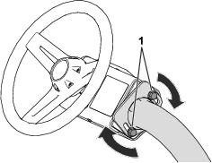
Tilting the Steering Wheel
You can tilt the steering wheel to a comfortable operating position.
Performing Daily Maintenance
Before starting the machine each day, perform the following procedures:
-
Check the engine-oil level; refer to Checking the Engine Oil.
-
Check the reel-to-bedknife contact; refer to Checking the Reel-to-Bedknife Contact.
-
Check the tire pressure; refer to Checking the Tire Pressure.
-
Check the safety-interlock system; refer to Understanding the Safety-Interlock System.
-
Check the fuel level and add more fuel if needed; refer to Filling the Fuel Tank.
-
Check the parking brake function by actuating the parking brake and ensuring that it engages; refer to Parking Brake.
During Operation
During Operation Safety
General Safety
-
The owner/operator can prevent and is responsible for accidents that may cause personal injury or property damage.
-
Wear appropriate clothing, including eye protection; long pants; substantial, slip-resistant footwear, and hearing protection. Tie back long hair and do not wear loose clothing or loose jewelry.
-
Do not operate the machine while ill, tired, or under the influence of alcohol or drugs.
-
Use your full attention while operating the machine. Do not engage in any activity that causes distractions; otherwise, injury or property damage may occur.
-
Before you start the engine, ensure that all drives are in neutral, the parking brake is engaged, and you are in the operating position.
-
Do not carry passengers on the machine.
-
Keep bystanders and children out of the operating area. If co-workers must be present, use caution and ensure that the grass baskets are installed on the machine.
-
Operate the machine only in good visibility to avoid holes or hidden hazards.
-
Avoid mowing on wet grass. Reduced traction could cause the machine to slide.
-
Keep your hands and feet away from the cutting units.
-
Look behind and down before backing up to be sure of a clear path.
-
Use care when approaching blind corners, shrubs, trees, or other objects that may obscure your vision.
-
Stop the cutting units whenever you are not mowing.
-
Slow down and use caution when making turns and crossing roads and sidewalks with the machine. Always yield the right-of-way.
-
Operate the engine only in well-ventilated areas. Exhaust gases contain carbon monoxide, which is lethal if inhaled.
-
Do not leave a running machine unattended.
-
Before you leave the operating position, do the following:
-
Park the machine on a level surface.
-
Lower the cutting units to the ground and ensure that they are disengaged.
-
Engage the parking brake.
-
Shut off the engine and remove the key.
-
Wait for all movement to stop.
-
-
Operate the machine only in good visibility and appropriate weather conditions. Do not operate the machine when there is the risk of lightning.
Rollover Protection System (ROPS) Safety
-
Do not remove any of the ROPS components from the machine.
-
Ensure that the seat belt is attached and that you can release it quickly in an emergency.
-
Always wear your seat belt.
-
Check carefully for overhead obstructions and do not contact them.
-
Keep the ROPS in safe operating condition by thoroughly inspecting it periodically for damage and keeping all the mounting fasteners tight.
-
Replace all damaged ROPS components. Do not repair or alter them.
Slope Safety
-
Slopes are a major factor related to loss of control and rollover accidents, which can result in severe injury or death. You are responsible for safe slope operation. Operating the machine on any slope requires extra caution.
-
Evaluate the site conditions to determine if the slope is safe for machine operation, including surveying the site. Always use common sense and good judgment when performing this survey.
-
Review the slope instructions, listed below, for operating the machine on slopes. Before you operate the machine, review the site conditions to determine whether you can operate the machine in the conditions on that day and at that site. Changes in the terrain can result in a change in slope operation for the machine.
-
Avoid starting, stopping, or turning the machine on slopes. Avoid making sudden changes in speed or direction. Make turns slowly and gradually.
-
Do not operate a machine under any conditions where traction, steering, or stability is in question.
-
Remove or mark obstructions such as ditches, holes, ruts, bumps, rocks, or other hidden hazards. Tall grass can hide obstructions. Uneven terrain could overturn the machine.
-
Be aware that operating the machine on wet grass, across slopes, or downhill may cause the machine to lose traction. Loss of traction to the drive wheels may result in sliding and a loss of braking and steering.
-
Use extreme caution when operating the machine near drop-offs, ditches, embankments, water hazards, or other hazards. The machine could suddenly roll over if a wheel goes over the edge or the edge caves in. Establish a safety area between the machine and any hazard.
-
Identify hazards at the base of the slope. If there are hazards, mow the slope with a pedestrian-controlled machine.
-
If possible, keep the cutting units lowered to the ground while operating on slopes. Raising the cutting units while operating on slopes can cause the machine to become unstable.
-
Use extreme caution with grass-collection systems or other attachments. These can change the stability of the machine and cause a loss of control.
Breaking in the Machine
Refer to the engine Owner’s Manual supplied with the machine for oil change and maintenance procedures recommended during the break-in period.
Only 8 hours of operation is required for the break-in period.
Since the first hours of operation are critical to future dependability of the machine, monitor its functions and performance closely so that minor difficulties, which could lead to major problems, are noted and can be corrected. Inspect the machine frequently during break-in for signs of oil leakage, loose fasteners, or any other malfunction.
Starting the Engine
Note: Inspect the areas beneath the cutting units to ensure that they are clear of debris.
-
If you are starting a cold engine, move the choke lever to the CLOSED position.
-
Insert and rotate the key to the ON position.
-
Wait until the splash screen appears on the InfoCenter, then move the key to the START position until the engine starts.
-
Once the engine starts, remove your hand from the key; the key will automatically move to the ON position.
-
Adjust the choke to run the engine smoothly. As soon as possible, open the choke by pulling it rearward to the OPEN position.
Note: A warm engine requires little or no choking.
Note: A fault occurs if the engine cranks longer than 30 seconds.
Checking the Machine after Starting the Engine
-
Sit in the operator’s seat and fasten the seatbelt.
-
Move the function-control switch to the MOW position.
-
Disengage the parking brake.
-
Move the lift/lower joystick forward momentarily.
The cutting units should lower and all the reels should rotate.
-
Move the lift/lower joystick rearward.
The cutting reels should stop rotating and the cutting units should raise to the full transport position.
Shutting Off the Engine
-
Transport the machine to a level surface.
-
Move the function-control switch to the NEUTRAL position.
-
Engage the parking brake.
-
Rotate the key to the OFF position to shut off the engine.
-
Remove the key.
Understanding the Safety-Interlock System
| Maintenance Service Interval | Maintenance Procedure |
|---|---|
| Before each use or daily |
|
Caution
If the safety interlock switches are disconnected or damaged the machine could operate unexpectedly, causing personal injury.
-
Do not tamper with the interlock switches.
-
Check the operation of the interlock switches daily and replace any damaged switches before operating the machine.
The purpose of the safety-interlock system is to prevent operation of the machine where there is possible injury to you or damage to the machine.
The safety-interlock system prevents the machine from moving unless:
-
The parking brake is disengaged.
-
You are seated in the operator's seat.
-
The function-control switch is in the MOW position or the TRANSPORT position.
Additionally, the safety-interlock system prevents the reels from operating unless the function-control switch is in the MOW position (except when the machine is in Backlap Mode).
Checking the Safety-Interlock System
Perform the following steps to check the interlock system:
-
Rise from the seat, start the engine, disengage the parking brake, move the function-control switch to the MOW or TRANSPORT position, and engage the traction pedal.
The machine should not move, as you are not in the seat. This indicates that the interlock system is operating correctly. Correct the problem if it is not operating properly.
-
Sit in the seat, start the engine, engage the parking brake, move the function-control switch to the MOW or TRANSPORT position, and engage the traction pedal.
The machine should not move, as the parking brake is engaged. This indicates that the interlock system is operating correctly. Correct the problem if it is not operating properly.
-
Sit in the seat, start the engine, disengage the parking brake, move the function-control switch to the NEUTRAL position, and engage the traction pedal.
The machine should not move, as the function-control switch is in the NEUTRAL position. This indicates that the interlock system is operating correctly. Correct the problem if it is not operating properly.
-
Sit on the seat, move the traction pedal to the NEUTRAL position, move the function-control switch to the NEUTRAL position, engage the parking brake, start the engine, and move the lift/lower joystick forward to lower the cutting units.
The cutting units should lower but not start rotating. If they start rotating, the interlock system is not operating correctly; correct the problem before operating the machine.
Driving the Machine without Mowing
-
Ensure that the cutting units are fully raised.
-
Sit in the seat, disengage the parking brake, and move the function-control switch to the TRANSPORT position to drive the machine without mowing.
-
Always approach rough areas at a reduced speed and cross severe undulations carefully.
-
Familiarize yourself with the width of the machine. Do not attempt to pass between objects that are close together to prevent costly damage and downtime.
Mowing the Green
Before mowing greens, find a clear area and practice performing basic machine functions (e.g., starting and stopping the machine, raising and lowering the cutting units, and turning).
Inspect the green for debris, remove anything that may damage the cutting units while mowing, remove the flag from the cup, and determine the best direction to mow. Base the direction to mow on the previous mowing direction. Always mow in an alternate pattern from the previous mowing so that the grass blades are less apt to lay down and will have a greater chance of being cut.
Cutting the Green
-
Start on 1 edge of the green so that you can use the ribbon procedure of cutting.
Note: This holds compaction to a minimum and leaves a neat, attractive pattern on the greens.
-
Move the function-control switch to the MOW position.
-
Push forward the lift/lower mow lever as the front edges of the grass baskets cross the outer edge of the green.
Note: This procedure drops the cutting units to the turf and starts the reels.
Important: The center cutting unit lifts or lowers slightly after the front cutting units do; therefore, you should practice gaining the required timing necessary to minimize the cleanup mowing operation and prevent scalping of the fringe.The center cutting unit lift and lower is based on ground speed. A slower ground speed increases the lift or lower delay; a faster speed decreases the lift or lower delay. The machine monitors the ground speed and updates this delay so that all three cutting units drop in a line.
-
Overlap a minimal amount with the previous cut on return passes.
Note: To assist in maintaining a straight line across the green and keeping the machine an equal distance from the edge of the previous cut, imagine a sight line approximately 1.8 to 3 m (6 to 10 ft) ahead of the machine to the edge of the uncut portion of the green (Figure 31). Include the outer edge of the steering wheel as part of the sight line; i.e., keep the steering wheel edge aligned with a point that is always kept the same distance away from the front of the machine.
-
As the front edges of the baskets cross the edge of the green, pull back the lift/lower joystick rearward and hold it until all the cutting units have risen. This stops the reels and lifts the cutting units.
Important: Time this step correctly so that you do not cut into the fringe area, yet cut as much of the green as possible to minimize the amount of grass left to mow around the outer periphery.
-
To cut down on operating time and to ease the lineup for the next pass, momentarily turn the machine in the opposite direction, then turn it in the direction of the uncut portion. This movement is a tear-shaped turn (Figure 30), which quickly lines the machine up for your next pass.
Note: If the slow in turn function is engaged, the machine slows down during the turn without requiring you to release pressure on the traction pedal.
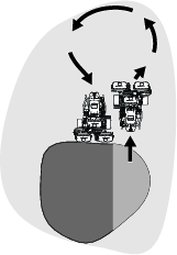
Note: Try to make as short of a turn as possible, except during warmer weather—a wider arc minimizes the turf bruising.
Important: Never stop the machine on a green, especially while the cutting units are engaged; damage to the turf may result. Stopping the machine on a green may leave marks or indentations from the wheels.
Cutting the Periphery and Finishing the Job
-
Finish cutting the green by mowing the outer periphery. Change the direction of cutting from the previous mowing.
Refer to Understanding the Radius-Dependent-Speed (RDS) System to improve the after-cut appearance and reduce triplex ring.
Note: Always keep weather and turf conditions in mind and be sure to change the direction of mowing from the previous cutting.
-
When you finish mowing the outer periphery, tap the lift/lower joystick rearward to stop the reels (if the tap-off delay feature is engaged), then drive off the green. When all the cutting units are off the green, move the lift/lower joystick rearward to raise the cutting units.
Note: This step minimizes grass clumps left on the green.
-
Replace the flag.
-
Empty the grass baskets of all clippings before you transport the machine to the next green.
Note: Heavy wet clippings cause strain on the baskets, suspensions, and actuators. This adds unnecessary weight to the machine, which decreases energy efficiency.
After Operation
After Operation Safety
General Safety
-
Engage the parking brake, shut off the engine, remove the key, and wait for all movement to stop before you leave the operator’s position. Allow the machine to cool before adjusting, servicing, cleaning, or storing it.
-
Clean grass and debris from the cutting units and drives to help prevent fires. Clean up oil or fuel spills.
-
Shut off the fuel while storing or hauling the machine.
-
Disengage the drive to the attachment whenever you are hauling or not using the machine.
-
Allow the machine to cool before storing the machine in any enclosure.
-
Maintain and clean the seat belt(s) as necessary.
-
Do not store the machine or fuel container where there is an open flame, spark, or pilot light, such as on a water heater or on other appliances.
Towing Safety
-
Tow only with a machine that has a hitch designed for towing. Do not attach towed equipment except at the hitch point.
-
Follow the manufacturer’s recommendation for weight limits for towed equipment and towing on slopes. On slopes, the weight of the towed equipment may cause loss of traction and loss of control.
-
Never allow children or others in or on towed equipment.
-
Travel slowly and allow extra distance to stop when towing.
Inspecting and Cleaning after Mowing
| Maintenance Service Interval | Maintenance Procedure |
|---|---|
| Before each use or daily |
|
After mowing, thoroughly wash the machine with a garden hose without a nozzle so that excessive water pressure does not contaminate and damage the seals, bearings, and electronics. Do not wash a warm engine or the electrical connections with water.
Important: Do not use brackish or reclaimed water to clean the machine.
Important: Do not use power-washing equipment to wash the machine. Power-washing equipment may damage the electrical system, loosen important decals, or wash away necessary grease at friction points. It may force water under seals, contaminating oil or grease contained housings. Avoid excessive use of water near the control panel, engine, and battery.
Important: Do not wash the machine with the engine running. Washing the machine with the engine running may result in internal engine damage.
Important: Do not force water into the muffler. Water inside the muffler may result in internal engine damage or reduced engine performance.
Inspect the cutting units for sharpness after you clean the machine.
Hauling the Machine
-
Use care when loading or unloading the machine into a trailer or a truck.
-
Use a full-width ramp for loading the machine into a trailer or a truck.
-
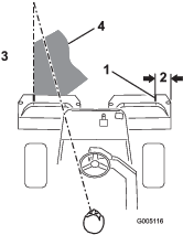
Tie the machine down securely using straps, chains, cable, or ropes. Both front and rear straps should be directed down and outward from the machine (Figure 32).
-
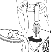
After the machine is secured for transport, close the fuel-shutoff valve.
Towing the Machine
Note: Refer to Figure 33 for this procedure.
To tow the machine, you must perform the following procedure to release the brake actuator:
-
Engage the parking brake.
-
Remove the key and disconnect the main-power connectors.
Important: If the main-power connectors are connected while towing, electrical damage may result.
-
Close the fuel-shutoff valve.
-
Chock both sides of the front tires.
-
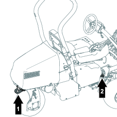
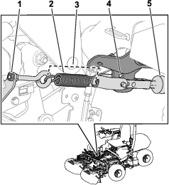
Release tension on the spring by loosening the nut that secures the eyebolt to the spring bracket.
-
Remove the spring.
-
Insert a ratchet (3/8 inch) through the hole of the arm bracket and push in the actuator shaft.
Danger
When the actuator is released from the brake, the machine is able to free wheel. A free-wheeling machine can cause serious injury to bystanders.
If the machine is not being towed, engage the parking brake.
-
Engage the parking brake.
-
Remove the chocks from the tires.
-
If the 3-Wheel Drive Kit is installed, disconnect the kit-wire-harness connectors from the main wire harness.
Important: If the kit and machine wire harnesses are connected while towing, electrical damage may result.
-
When the machine is ready to be towed, disengage the parking brake.
-
Have an assistant sit in the seat, fasten the seatbelt, and use the brake while you tow the machine.
Note: This ensures that the machine is under control when you tow the machine over undulations and slopes.
-
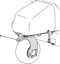
Use the rear castor fork to tow the machine (Figure 34).
Important: Do not exceed 5 km/h (3 mph) while towing the machine. Damage to the electrical components may result.
After you have towed the machine to your intended destination, perform the following steps:
-
Engage the parking brake.
-
Remove the tow strap from the castor fork.
-
Prepare for operation by tightening the eyebolt nut so that the spring length is 11.4 cm (4.5 inches) when installed (Figure 33).
Driving the Machine Without Engine Power
You can drive the machine using the battery power of the machine. This feature can be used for the following scenarios:
-
Moving the machine in the maintenance shop.
-
Moving the machine off of the green if the engine shuts off.
The machine can be transported only; you cannot engage the cutting units. This feature lasts for 1 minute, and you can cycle the key switch to reset the minute of transport time.
-
Sit in the operator’s seat and fasten the seatbelt.
-
Move the key to the ON position.
-
Move the function-control switch to the MOW or TRANSPORT position.
-
Disengage the parking brake.
-
Use the traction pedal to transport the machine.
Note: Forward ground speed is limited to 4.8 km/h (3.0 mph), and reverse ground speed is limited to 4.0 km/h (2.5 mph).
Important: Excessive or prolonged use of this feature may decrease the life of the batteries.
Maintenance
Maintenance Safety
-
Before you leave the operator’s position, do the following:
-
Park the machine on a level surface.
-
Disengage the cutting unit(s).
-
Engage the parking brake.
-
Shut off the engine and remove the key.
-
Wait for all movement to stop.
-
-
Allow machine components to cool before performing maintenance.
-
If possible, do not perform maintenance while the engine is running. Keep away from moving parts.
-
Support the machine with jack stands whenever you work under the machine.
-
Carefully release pressure from components with stored energy.
-
Keep all parts of the machine in good working condition and all hardware tightened.
-
Replace all worn or damaged decals.
-
To ensure safe, optimal performance of the machine, use only genuine Toro replacement parts. Replacement parts made by other manufacturers could be dangerous, and such use could void the product warranty.
Recommended Maintenance Schedule(s)
| Maintenance Service Interval | Maintenance Procedure |
|---|---|
| After the first 8 hours |
|
| After the first 50 hours |
|
| Before each use or daily |
|
| Every 25 hours |
|
| Every 50 hours |
|
| Every 100 hours |
|
| Every 200 hours |
|
| Every 800 hours |
|
| Every 1,000 hours |
|
| Every 2 years |
|
Pre-Maintenance Procedures
Raising the Machine
Danger
Mechanical or hydraulic jacks may fail to support the machine and cause a serious injury.
-
Use jack stands to support the raised machine.
-
Use only mechanical or hydraulic jacks to lift the machine.
-
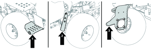
Position a jack at the desired jacking point (Figure 35):
-
Foot step on the left side of the machine
-
Jack bracket on the right side of the machine
-
Caster fork on the rear of the machine
-
-
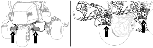
After raising the machine, use an appropriate jack stand under the following areas to support the machine (Figure 36):
-
Battery trays at the rear of the machine
-
Cutting-unit pivot mounts at the front of the machine
-
Engine Maintenance
Engine Safety
-
Shut off the engine before checking the oil or adding oil to the crankcase.
-
Do not change the governor speed or overspeed the engine.
Servicing the Air Cleaner
| Maintenance Service Interval | Maintenance Procedure |
|---|---|
| Every 25 hours |
|
| Every 100 hours |
|
| Every 200 hours |
|
Inspect the foam and paper elements and replace them if they are damaged or excessively dirty.
Important: Do not oil the foam or paper element.
Removing the Foam and Paper Elements
-
Park the machine on a level surface, lower the cutting units, and engage the parking brake.
-
Shut off the engine and remove the key.
-
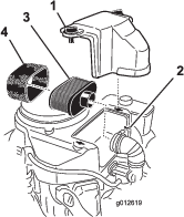
Clean around the air cleaner to prevent dirt from getting into the engine and causing damage (Figure 38).
-
Loosen the cover knobs and remove the air-cleaner cover (Figure 38).
-
Loosen the hose clamp and remove the air-cleaner assembly (Figure 38).
-
Carefully pull the foam element off the paper element (Figure 38).
Cleaning the Foam Air-Cleaner Element
-
Wash the foam element in liquid soap and warm water. When the element is clean, rinse it thoroughly.
-
Dry the element by squeezing it in a clean cloth.
Important: Do not twist the foam element, as it may tear.Replace the foam element if it is torn or worn.
Servicing the Paper Air-Cleaner Element
-
Clean the paper element by tapping it gently to remove dust. If it is very dirty, replace the paper element (Figure 38).
-
Inspect the element for tears, an oily film, or damage to the rubber seal.
-
Replace the paper element if it is damaged.
Important: Do not clean the paper filter.
Installing the Foam and Paper Air-Cleaner Elements
Important: To prevent engine damage, always operate the engine with the complete foam and paper air-cleaner assembly installed.
Servicing the Engine Oil
The engine is shipped with oil in the crankcase; however, you must check the oil level before and after starting the engine the first time.
Engine-Oil Specification
API Oil Service Classification: SJ or higher
Oil Viscosity: SAE 30
Note: Use any high-quality detergent oil.
Checking the Engine Oil
| Maintenance Service Interval | Maintenance Procedure |
|---|---|
| Before each use or daily |
|
Caution
Engines can become extremely hot during normal operation.
Allow the engine to cool before you check the oil or perform any engine maintenance.
Refer to Figure 39 for this procedure.
-
Park the machine on a level surface, lower the cutting units, engage the parking brake, shut off the engine, and remove the key.
-
Unscrew the dipstick, remove it, and wipe it with a clean rag.
-
Insert the dipstick into the dipstick tube.
-
Pull the dipstick out of the tube and check the oil level.
-
If the oil level is low, add oil into the engine through the dipstick tube until the oil level is up to the FULL mark on the dipstick.
Add the oil slowly and check the level often during this process.
Important: Do not overfill the engine with oil.
-
Install the dipstick.

Changing the Engine Oil and Filter
| Maintenance Service Interval | Maintenance Procedure |
|---|---|
| After the first 8 hours |
|
| Every 100 hours |
|
Caution
Engines can become extremely hot during normal operation.
Allow the engine to cool before you change the oil or oil filter, or perform any engine maintenance.
Engine oil quantity: 1.7 L (1.8 US qt) with filter
-
Remove the drain plug (Figure 40) and let the oil flow into a drain pan.
-
Clean the threads of the drain plug and install the drain plug (Figure 40).
-
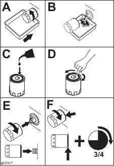
Remove the oil filter (Figure 41).

-
Apply a light coat of clean oil to the new filter gasket.
-
Screw the filter on by hand until the gasket contacts the filter adapter, then tighten it 3/4 to 1 turn further. Do not overtighten it.
-
Add oil to the crankcase; refer to Checking the Engine Oil.
-
Dispose of the oil filter and used oil properly.
Servicing the Spark Plug
| Maintenance Service Interval | Maintenance Procedure |
|---|---|
| Every 100 hours |
|
Caution
Engines can become extremely hot during normal operation.
Allow the engine to cool before you service the spark plug or perform any engine maintenance.
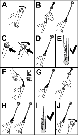
Ensure that the air gap between the center and side electrodes is correct before installing the spark plug. Use a spark plug wrench for removing and installing the spark plug(s) and a gapping tool/feeler gauge to check and adjust the air gap. Install a new spark plug(s) if necessary.
Type of Spark Plug: NGK® BPR4ES or equivalent
Air Gap: 0.75 mm (0.03 inch)
Removing the Spark Plug
-
Park the machine on a level surface, lower the cutting units, and engage the parking brake.
-
Shut off the engine and remove the key.
-
Locate the spark-plug caps.
-
Clean the area around the spark plug caps so that foreign matter cannot fall into the cylinder.
-
Disconnect the spark plug caps from the spark plugs (Figure 42).
-
Remove the spark plugs from the engine.
Checking and Cleaning the Spark Plug
Important: Always replace the spark plug(s) when it has a black coating, worn electrodes, an oily film, or cracks.
-
Clean the spark plug with a wire brush to remove any carbon deposits.
Use carburetor cleaner to wash the plug and ensure any foreign matter has been removed.
-
Inspect the spark plugs for cracks, worn electrodes, black coating, or oily films or other wear or damage.
-
Replace the spark plug if necessary. Replace all spark plugs if only one requires replacing.
-
Check the spark plug gap and reset if necessary. To change the gap, bend only the side-electrode, using a spark plug tool.
Set the gap to 0.75 mm (0.03 inch).
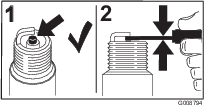
If you see light brown or gray on the insulator, the engine is operating properly. A black coating on the insulator usually means the air cleaner is dirty.
Installing the Spark Plug
Refer to Figure 44 for this procedure.
-
Install the spark plug into the engine.
-
Torque the spark plug to 22 N∙m (16 ft-lb).
-
Reconnect the spark plug caps.
Fuel System Maintenance
Replacing the Fuel Filter
| Maintenance Service Interval | Maintenance Procedure |
|---|---|
| Every 1,000 hours |
|
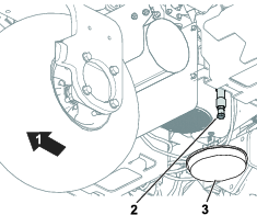
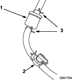
The in-line fuel filter is between the fuel-shutoff valve and the engine.
Danger
In certain conditions, fuel is extremely flammable and highly explosive. A fire or explosion from fuel can burn you and others and can damage property.
-
Drain fuel from the fuel tank when the engine is cold. Do this outdoors in an open area. Wipe up any fuel that spills.
-
Never smoke when draining fuel, and stay away from an open flame or where a spark may ignite the fumes.
-
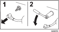
Close the fuel-shutoff valve (Figure 45).
-
Place a drain pan under the filter, loosen the hose clamp on the carburetor side of filter, and remove the fuel line from the filter (Figure 45).
-
Loosen the other hose clamp and remove the filter.
-
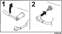
Inspect the fuel lines for any cracks, deterioration, or damage and replace if necessary.
-
Install the new filter with the arrow on the filter body pointing away from the fuel tank.
-
Ensure the hoses and hose clamps are secure to the filter.
-
Open the fuel-shutoff valve and fill the tank. Inspect the fuel lines for any leaks or loose connections.
Inspecting the Fuel Lines and Connections
| Maintenance Service Interval | Maintenance Procedure |
|---|---|
| Every 2 years |
|
Inspect the fuel lines for deterioration, damage, or loose connections.
Electrical System Maintenance
Electrical System Safety
-
Disconnect the main-power connectors before repairing the machine.
-
Charge the battery in an open, well-ventilated area, away from sparks and flames. Unplug the charger before connecting or disconnecting the battery. Wear protective clothing and use insulated tools.
Disconnecting or Connecting Power to the Machine
The main-power connectors provide power from the batteries to the machine. Disconnect the power by separating the connectors; connect the power by installing the connectors together. Refer to Main-Power Connectors.
Charging the 12V Battery to the 12V System
Warning
Incorrect battery cable routing could damage the machine and cables causing sparks. Sparks can cause the battery gasses to explode, resulting in personal injury.
-
Always disconnect the negative (black) battery cable before disconnecting the positive (red) cable.
-
Always connect the positive (red) battery cable before connecting the negative (black) cable.
The 12V AGM (absorbed glass mat) battery (Figure 46) powers the InfoCenter, brake actuator, machine controller, and the CAN isolation module.
-
Remove the right side cover.
-
Remove the battery cover.
-
Disconnect the battery cables from the batteries.
-
Connect the charger to the battery terminals and charge the battery.
Note the following information for your battery charger:
-
Ensure that the battery-charger connectors do not contact each other or the machine frame. Using smaller connectors is recommended.
-
A battery charger with an AGM-charging setting is preferred.
-
Maximum charge current: 2.4 A
-
Maximum charge voltage: 14.3 V
-
-
Connect the battery cables to the battery when the charge is completed.
-
Install the battery cover over the battery.
-
Install the right side cover.
Understanding the 48V Battery System
Important: Charging the 48V battery system is not recommended.
The 48V battery system consists of 4 batteries (12V, AGM [absorbed glass mat]). The batteries are located under covers on each side of the machine; refer to Figure 47. This system provides power to the traction wheels, cutting-unit motors, steering motor, and lift actuators.
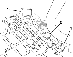
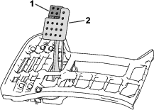
Locating the Fuses
Locating the Fuses for the 48V System
The fuses in the 48V electrical system are located under the seat (Figure 48).
Locating the Fuses for the 12V System
Locating the Reel-Drive Circuit Fuses
Locating the Generator, Wheel Motor, and Electrical System Fuses
-
The fuses for the generator (100 A) and the right wheel motor (60 A) are located under the seat (Figure 53).
-
The fuse for the left wheel motor (60 A) is located under the cover on the left side of the machine, near the reel-drive-circuit fuses (Figure 54).
-
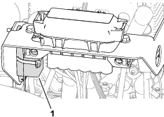
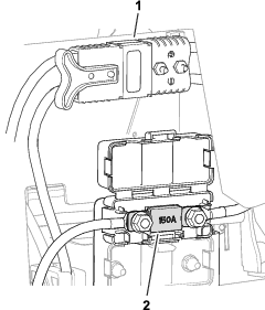
The fuse for the electrical system is located under the main-power connectors (Figure 55).
Drive System Maintenance
Checking the Tire Pressure
| Maintenance Service Interval | Maintenance Procedure |
|---|---|
| Before each use or daily |
|
Vary the tire pressure for all 3 wheels, depending upon your turf conditions, from a minimum of 83 to a maximum of 110 kPa (12 psi to 16 psi).
Important: Ensure that the tire pressure for each wheel is identical. If the tire pressure for each wheel is different, the performance of the machine is affected.
Checking the Torque of the Wheel Nuts
| Maintenance Service Interval | Maintenance Procedure |
|---|---|
| After the first 8 hours |
|
| Every 200 hours |
|
Warning
Failure to maintain proper torque of the wheel nuts could result in personal injury.
Torque the wheel nuts to the specified torque at the specified intervals.
Wheel-nut torque specification: 108 to 122 N∙m (80 to 90 ft-lb)
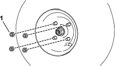
To ensure even distribution, torque the wheel nuts in the pattern shown in Figure 56.

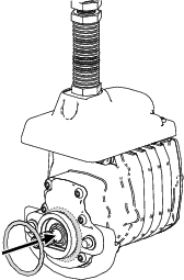
Changing the Traction-Motor-Gearbox Fluid
| Maintenance Service Interval | Maintenance Procedure |
|---|---|
| After the first 8 hours |
|
| Every 800 hours |
|
Fluid specification: SAE 80W90
Gearbox oil capacity: approximately 384 ml (13 fl oz)
-
Raise the machine; refer to Raising the Machine.
Important: The machine must be level so that the correct amount of fluid can be added to the gearbox.Ensure that the machine is level on the jack stands.
-
Perform the following steps to remove the left and right-sided tires:
-
Loosen and remove the wheel lug nuts (Figure 57).
-
Remove the left and right tires.
-
-
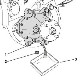
Place a drain pan under the wheel-motor assembly (Figure 58).
-
Remove the plug from the drain port (Figure 58).
Note: The drain port is located on the bottom of the gearbox.
Note: Allow the oil to drain completely from the gearbox.
-
Clean the plug.
-
Install the drain plug into the drain port (Figure 58).
-
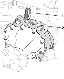
Remove the vent hose and fitting from the top of the gearbox (Figure 59).
-
Fill the gearbox with 384 ml (13 fl oz) of the specified fluid through the fill port.
-
Install the vent hose and fitting into the fill port (Figure 59).
-
Perform the following steps to install the tires:
-
Slide the left and right tires on to the wheel hubs.
-
Install the wheel lug nuts (Figure 57).
-
Torque the wheel lug nuts to the specified torque indicated in Checking the Torque of the Wheel Nuts.
-
Brake Maintenance
Adjusting the Brakes
If the brake fails to hold the machine while parked, you can adjust the brakes; contact your authorized Toro distributor or refer to the Service Manual for more information.
Cutting Unit Maintenance
Blade Safety
A worn or damaged blade or bedknife can break, and a piece could be thrown toward you or bystanders, resulting in serious personal injury or death.
-
Inspect the blades and bedknives periodically for excessive wear or damage.
-
Use care when checking the blades. Wear gloves and use caution when servicing them. Only replace or backlap the blades and bedknives; never straighten or weld them.
-
On machines with multiple cutting units, take care when rotating a cutting unit; it can cause the reels in the other cutting units to rotate.
Installing and Removing the Cutting Units
Note: When the cutting units are not connected to the machine, store the cutting unit reel motors in the storage location on the front of the suspension arms to prevent damage to them.
Important: Do not raise the suspension to the transport position when the reel motors are in the holders in the machine frame. Damage to the motors or hoses could result.
Important: Whenever you need to tip the cutting unit, prop up rear of cutting unit to ensure that the nuts on the bedbar adjusting screws are not resting on work surface (Figure 60).
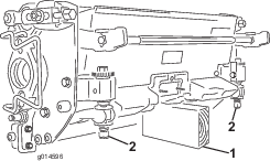
Installing the Cutting Units
Caution
Contact with a hot engine or muffler can cause severe burns.
Wait for a hot engine or muffler to cool before installing the cutting units.
The suspension needs to be lowered in order to install the cutting units. Perform the following steps to lower the suspension:
-
Park the machine on a clean, level surface.
-
Set the function-control switch to the NEUTRAL position.
-
Start the engine or turn the key to the ON position.
-
Lower the suspension using the lift/lower joystick.
-
Engage the parking brake, shut off the engine, and remove the key.
Perform the following steps to install the cutting units:
-
Disconnect the main-power connectors; refer to Main-Power Connectors.
Caution
If you do not disconnect the power to the machine, someone could accidentally start the cutting units, causing serious injury to hands and feet.
Always disconnect the main-power connectors before working on the cutting units.
-
Lift up on the foot rest and swing it open, allowing access to the center cutting unit position (Figure 61).
Caution
The foot rest can pinch fingers if it falls into the closed position.
Keep your fingers clear of the area where the foot rest seats while it is open.
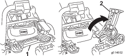
-
Position the cutting unit under the center suspension arm.
-
Open the latches on the suspension-arm bar (Figure 62) and push the suspension arm down so that the bar fits over both pitch arms on the cutting unit and ensure that the latches go underneath the cutting-unit crossbar (Figure 63).
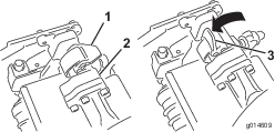
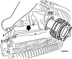
-
Close the latches down and around the cutting-unit bar and lock them in place (Figure 62).
Note: You can hear a click and feel when the latches are properly locked in place.
-
Coat the spline shaft of the cutting unit motor with clean grease (Figure 64).
-
Insert the motor into the left side of the cutting unit (as viewed from the operator's position) and pull the motor retaining bar on the cutting unit toward the motor until you hear a click from both sides of the motor (Figure 64).
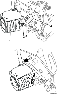
-
Mount a grass basket onto the basket hooks on the suspension arm.
-
Repeat this procedure for the other cutting units.
-
Connect the main-power connectors; refer to Main-Power Connectors.
Removing the Cutting Units
Caution
Contact with a hot engine or muffler can cause severe burns.
Wait for a hot engine or muffler to cool before installing the cutting units.
-
Park the machine on a clean, level surface, set the function-control switch to the NEUTRAL position and use the lift/lower joystick to lower the cutting units.
-
Engage the parking brake, shut off the engine, and remove the key.
-
Disconnect the main-power connectors; refer to Main-Power Connectors.
Caution
If you do not disconnect the power to the machine, someone could accidentally start the cutting units, causing serious injury to hands and feet.
Always separate the disconnect the main-power connectors before working on the cutting units.
-
Push the motor retaining bar out of the slots on the motor toward the cutting unit and remove the motor from the cutting unit.
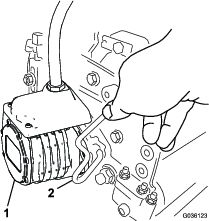
-
Move the motor to the storage location on the front of the suspension arm (Figure 66).
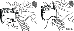
Note: When sharpening, setting the height-of-cut, or performing other maintenance procedures on the cutting units, store the cutting unit reel motors in the storage location on the front of the suspension arms to prevent damage to them.
Important: Do not raise the suspension to the transport position when the reel motors are in the holders in the machine frame. Damage to the motors or hoses could result. If you must move the traction unit without the cutting units installed, secure them to the suspension arms using cable ties.
-
Open the latches on the suspension-arm bar of the cutting unit you are removing (Figure 62).
-
Disconnect the latches from the cutting-unit bar.
-
Roll the cutting unit out from under the suspension arm.
-
Repeat steps 4 through 8 for the other cutting units as required.
-
Connect the main-power connectors; refer to Main-Power Connectors.
Checking the Reel-to-Bedknife Contact
| Maintenance Service Interval | Maintenance Procedure |
|---|---|
| Before each use or daily |
|
Each day before operating the machine, check the reel-to-bedknife contact, regardless if the quality of cut had previously been acceptable. There must be light contact across the full length of the reel and bedknife; refer to the cutting unit Operator’s Manual.
Before checking the reels, disconnect the main-power connectors; refer to Main-Power Connectors. Connect them when finished.
Backlapping the Cutting Units
Warning
Contact with the bedknives, reel blades, or other moving parts can result in personal injury.
-
Keep your fingers, hands, and clothing away from the bedknives, reel blades, or moving parts.
-
Never attempt to turn the reels by hand or foot while the engine is running.
-
Park the machine on a level surface, lower the cutting units, move the function-control switch to the NEUTRAL position, engage the parking brake, shut off the engine, and remove the key.
-
Make initial reel-to-bedknife adjustments appropriate for backlapping on all cutting units that you want to backlap; refer to the cutting unit Operator’s Manual.
-
Insert the key into the switch and start the engine.
-
On the InfoCenter control, from the SERVICE menu, select BACKLAP.
-
Set BACKLAP to ON.
-
Pull up the Main Menu and scroll down to Settings.
-
In the SETTINGS menu scroll down to BACKLAP RPM and use the ± button to select the desired backlap speed.
-
With the function-control switch in the NEUTRAL position, move the lift/lower joystick forward to start the backlapping operation on the designated reels.
-
Apply lapping compound with a long handle brush. Never use a short handled brush.
-
If the reels stall or become erratic while backlapping, select a higher reel speed setting until the speed stabilizes.
-
To make an adjustment to the cutting units while backlapping, turn the reels off by moving the lift/lower joystick rearward and shut off the engine. After completing adjustments, repeat steps 3 through 9.
-
Repeat the procedure for all cutting units that you want to backlap.
-
When finished, return the InfoCenter BACKLAP setting to OFF or turn the key to the OFF position to return the machine to forward cutting operation.
-
Wash all lapping compound off of the cutting units. Adjust the cutting unit reel to bedknife as needed. Move the cutting-unit reel speed control to the desired mowing position.
Important: Do not use high pressure water to clean off the cutting units. Damage to the bearings and seals may result.
Storage
If you wish to store the machine for a long period of time, perform the steps listed in Preparing the Machine for Storage.
Storage Safety
-
Shut off the machine, remove the key, and wait for all movement to stop before you leave the operator’s position. Allow the machine to cool before adjusting, servicing, cleaning, or storing it.
-
Do not store the machine or fuel container where there is an open flame, spark, or pilot light, such as on a water heater or other appliance.
Preparing the Machine for Storage
If possible, store the machine in a warm, dry location.
The batteries—whether they are installed or removed from the machine—must be stored in the appropriate environment:
-
Recommended storage temperatures should be between 10°C to 25°C (50°F and 77°F).
-
Storage at extreme temperatures will result in accelerated rates of self discharge.
-
If temperatures are expected to drop well below freezing for an extended period, remove the batteries from the machine and store the batteries in a warmer environment.
-
Disconnect the main-power connectors; refer to Main-Power Connectors.
-
Remove accumulations of dirt and old grass clippings. Sharpen the reels and bedknives, if necessary; refer to the cutting unit Operator's Manual. Coat the bedknives and reel blades with a rust preventive.
-
All fuel should be removed from the fuel tank. Run the engine until it shuts off. Replace the fuel filter; refer to Replacing the Fuel Filter.
-
While the engine is still warm, drain the oil from the crankcase. Refill it with fresh oil; refer to Changing the Engine Oil and Filter.
-
Remove the spark plugs, pour 30 ml (1 fl oz) of SAE 30 oil into the cylinders, and crank to distribute the oil. Replace the spark plugs; refer to Servicing the Spark Plug.
-
Clean dirt and chaff from the cylinder, cylinder head fins, and blower housing.
-
Disconnect the battery cables from the 12V battery.
-
Ensure that the 12V and 48V batteries are fully charged; refer to the traction unit Service Manual for charging instructions.
For every 6 months of storage, check the battery-charge level and charge the battery.
-
Raise and support the machine to remove its weight from the tires.