| Maintenance Service Interval | Maintenance Procedure |
|---|---|
| Before each use or daily |
|
Introduction
This machine is intended for use by professional, hired operators in commercial applications. It is designed for mowing grass on well-maintained lawns in parks, golf courses, sports fields, and on commercial grounds.
Important: Read this information carefully to learn how to operate and maintain your product properly and to avoid injury and product damage. You are responsible for operating the product properly and safely.
Visit www.Toro.com for product safety and operation training materials, accessory information, help finding a dealer, or to register your product.
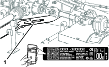
Whenever you need service, genuine Toro parts, or additional information, contact an Authorized Service Dealer or Toro Customer Service and have the model and serial numbers of your product ready. Figure 1 identifies the location of the model and serial numbers on the product. Write the numbers in the space provided.
Important: With your mobile device, you can scan the QR code on the serial-number decal (if equipped) to access warranty, parts, and other product information.
This manual identifies potential hazards and has safety messages identified by the safety-alert symbol (Figure 2), which signals a hazard that may cause serious injury or death if you do not follow the recommended precautions.

This manual uses 2 words to highlight information. Important calls attention to special mechanical information and Note emphasizes general information worthy of special attention.
This product complies with all relevant European directives; for details, please see the separate product specific Declaration of Conformity (DOC) sheet.
This machine has been designed in accordance with ANSI B71.4-2017.
Warning
CALIFORNIA
Proposition 65 Warning
Use of this product may cause exposure to chemicals known to the State of California to cause cancer, birth defects, or other reproductive harm.
Safety
General Safety
This product is capable of amputating hands and feet and of throwing objects. Always follow all safety instructions to avoid serious personal injury
-
Read and understand the contents of this Operator’s Manual before starting the machine.
-
Use your full attention while operating the machine. Do not engage in any activity that causes distractions; otherwise, injury or property damage may occur.
-
Do not put your hands or feet near moving components of the machine.
-
Do not operate the machine without all guards and other safety protective devices in place and functioning properly on the machine.
-
Keep clear of any discharge opening.
-
Keep bystanders and children out of the operating area. Never allow children to operate the machine.
-
Before you leave the operator’s position, do the following:
-
Park the machine on a level surface.
-
Lower the cutting unit(s).
-
Disengage the drives.
-
Engage the parking brake (if equipped).
-
Shut off the engine and remove the key.
-
Wait for all movement to stop.
-
Improperly using or maintaining this machine can result in injury.
To reduce the potential for injury, comply with these safety instructions
and always pay attention to the safety-alert symbol  , which means Caution, Warning,
or Danger—personal safety instruction. Failure to comply with
these instructions may result in personal injury or death.
, which means Caution, Warning,
or Danger—personal safety instruction. Failure to comply with
these instructions may result in personal injury or death.
Safety and Instructional Decals
 |
Safety decals and instructions are easily visible to the operator and are located near any area of potential danger. Replace any decal that is damaged or missing. |

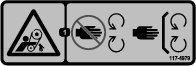

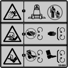


CE entanglement decal 138-9038

Setup
Applying the Entanglement Decal
CE Mowers
Parts needed for this procedure:
| CE entanglement decal | 4 |
Important: This procedure is required for all CE countries and anywhere English is not commonly spoken.
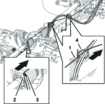
-
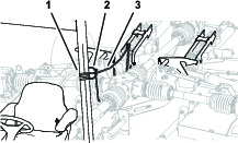
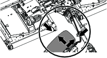
Rotate the shaft guard to access the existing entanglement decal (Figure 3).
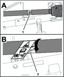
-
Clean the existing entanglement decal and the guard area surrounding the decal.
-
Remove the backing from the CE entanglement decal.
-
Place the CE entanglement decal over the existing entanglement decal (Figure 3).
-
Repeat steps 1 through 4 for the 3 other shaft guards.
Installing the Deck Cover Knobs
Non-CE Mowers
Parts needed for this procedure:
| Knob | 6 |
-
Remove the mower deck covers; refer to Removing the Deck Covers.
-
Remove the push-nut that secures the bolt to the deck cover and remove the bolt from the cover (Figure 4).
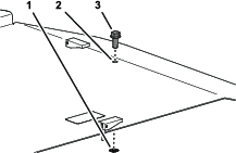
-
Install the mower deck cover with the knob; refer to Installing the Deck Covers.
-
Repeat steps 1 through 3 for the remaining deck covers,
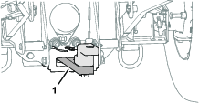
Adjusting the Drawbar Position of the Tow Vehicle
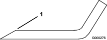
Adjust the drawbar (Figure 5) of the tow vehicle to the extended position; refer to the Operator’s Manual for your tow vehicle.
Adjusting the Tow Bar of the Mower
Assessing the Job Site
Consider the following job site conditions to determine the tow bar position of the mower:
-
Turf with hills and dips in the contour—set the tow bar to a shorter length.
-
Turf that is primarily flat—set the tow bar to a longer length.
Note: You may need to try an intermediate position tow-bar length when job site has a mixture of flat and hilly areas.
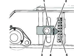
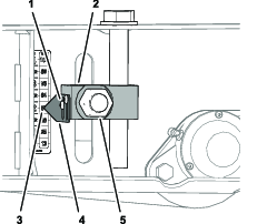
Adjusting the Tow-Bar Length
Note: The tow bar of the mower has 5 tow-bar positions allowing you to adjust the length 20 cm (8 inches).
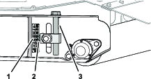
-
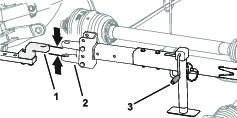
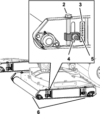
Remove the 2 flange locknuts, 2 capscrews, and 2 washers that secure the hitch tube to the receiver tube (Figure 6).
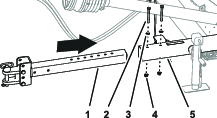
-
Adjust the position of the hitch tube in the receiver tube according to the position that you determined in Assessing the Job Site.
-
Assemble the hitch tube to the receiver tube with the flange locknuts, capscrews, and washers that you removed in step 1.
-
Torque the nuts and capscrews to 91 to 113 N∙m (67 to 83 ft-lb).
Adjusting the Clevis Hitch
Parts needed for this procedure:
| Hitch Pin | 2 |
| Hairpin Cotter | 2 |
Note: Contact your authorized Toro distributor to obtain the optional pintle hitch.
-
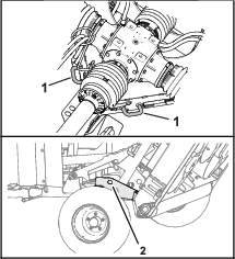
Measure the height from the ground to the top of the hitch on the tow vehicle.
-
Adjust the transport frame hitch up or down according to the measurement of the machine hitch. Use the appropriate mounting holes as shown in the table below and in Figure 7.
Tow Vehicle Hitch Height Frame Mounting Holes Below 36 cm (14 inches) Use holes 2 and 4 Above 36 cm (14 inches) Use holes 1 and 3 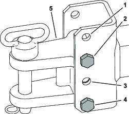
-
Secure the frame hitch to the machine hitch with the hitch pin and hairpin; refer toConnecting the Mower to the Tow Vehicle.
-
Remove the ball pin from the jack and rotate the jack so that it is in storage position. Install the ball pin to secure it in the storage position.
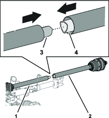
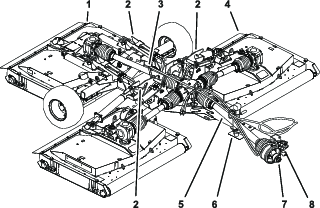
Assembling the PTO Driveshaft
Parts needed for this procedure:
| PTO driveshaft half (forward) | 1 |
-
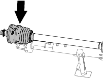
Align the inner tube of the rear PTO-driveshaft half with the outer tube of the forward PTO-driveshaft half, and slip the tubes together (Figure 8).
Important: The ends of the inner and outer PTO driveshaft tubes assemble only 1 way—do not force them together.
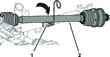
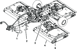
-
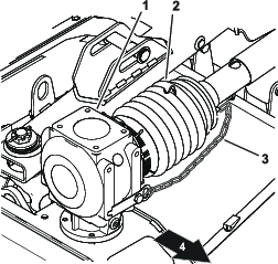
Move the PTO driveshaft onto the driveshaft rest of the hose guide (Figure 9).
-
Partially extend the PTO driveshaft to access the grease fitting near the middle of the inboard driveshaft guard (Figure 10).
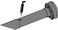
-
Apply grease to the grease fitting for the telescoping driveshaft joint as shown in Figure 10.
Installing the Deck-Lock Rope to the Mower
Product Overview
Note: Specifications and design are subject to change without notice.
| Minimum PTO output-power rating | 26 Kw (35 hp) |
| Recommended PTO speed | 540 rpm |
| PTO Rotation | Clockwise (viewed from behind the tow vehicle) |
| PTO spindle | 34.8 mm (1-3/8 inch) diameter, 6-spline |
| Minimum hydraulic pressure | 13 790 Kpa (2000 psi) |
| Tow system | Drawbar and pin—25 mm (1 inch) diameter |
| Clevis hitch (see an authorized Toro distributor for an optional pintle hitch) |
| Weight | 1354 kg (2984 lb) | |
| Tongue weight | 313 kg (691 lb) | |
| Width | Mow position | 381 cm (150 inches) |
| Transport position—13 mm (1/2 inch) HOC | 218 cm (86 inches) | |
| Height | Mow position | 78 cm (31 inches) |
| Transport position | 193 cm (76 inches) | |
| Length | Hitch fully extend | 371 cm (146 inches) |
| Width of cut | 365 cm (144 inches) | |
| Cut height | 13 to 102 mm (1/2 to 4.0 inches) | |
| Cutting Capacity | 9.7 km/h (6 mph) | 3.5 hectar / hr (8.7 acres / hr) |
| Maximum Transport Speed | 30 kph (19 mph) |
Attachments/Accessories
A selection of Toro approved attachments and accessories is available for use with the machine to enhance and expand its capabilities. Contact your Authorized Service Dealer or Distributor or go to www.Toro.com for a list of all approved attachments and accessories.
To ensure optimum performance and continued safety certification of the machine, use only genuine Toro replacement parts and accessories. Replacement parts and accessories made by other manufacturers could be dangerous, and such use could void the product warranty.
Operation
Before Operation
Before Operation Safety
General Safety
-
Never allow children or untrained people to operate or service the machine. Local regulations may restrict the age of the operator. The owner is responsible for training all operators and mechanics.
-
Keep your hands clear of the joint pivot areas when handling the PTO driveshaft.
-
Do not step on, over or under the PTO or driveshafts.
-
Become familiar with the safe operation of the equipment, operator controls, and safety signs.
-
Know how to stop the machine and shut off the engine quickly.
-
Do not use PTO spline adapters or extensions.
-
Use only a tow vehicle with the mower that has a maximum PTO speed of 540 rpm (9 rotations per second).
-
Ensure that the guards and shields are properly installed and maintained. Replace missing, damaged, or worn guards and shields before using the machine.
-
Ensure that the PTO driveshaft does not contact the drawbar
-
Before mowing, always inspect the machine to ensure that the blades, blade bolts, and cutting assemblies are in good working condition. Replace worn or damaged blades and bolts in sets to preserve balance.
-
Inspect the area where you will use the machine and remove all objects that the machine could throw.
-
Ensure that your tow vehicle is suitable for use with a mower of this weight by checking with your tow vehicle supplier or manufacturer.
Tractor Controls
Become familiar with operating the following tractor controls before you operate the mower:
-
PTO engagement
-
Engine/PTO speed
-
The rear attachment control (raise/lower)
-
Auxiliary valve operation
-
Clutch
-
Throttle
-
Gear selection
-
Parking brake
Important: Refer to the tractor Operator's Manual for operating instructions.
Outcross Traction Unit Controls
Refer to the Outcross traction unit Operator’s Manual for information on controls and operation, as well as additional information on setting up the vehicle for this attachment.
PTO Speed
The mower is designed to operate with a PTO speed of up to 540 rpm. Most tow vehicles indicate a 540 PTO rpm position on the tachometer.
Training Period
Before using the mower, find a clear area and practice using the it. Operate the tow vehicle at recommended gear settings and PTO drive speeds and become thoroughly familiar with driving characteristics of the tow vehicle and the mower. Practice raising and lowering mower decks, stopping, and starting the PTO drive, and aligning the machine with previous passes. Practice sessions increase confidence in the operating the mower and helps ensure use of proper techniques cutting grass.
Caution
A running attachment can cause personal injury.
To avoid personal injury, do not leave the operator’s seat without first disengaging the PTO drive, engaging the parking brake, shutting off the engine, and removing the key. Ensure that all safety devices are secured in their proper place before resuming operation.
Checking the Tire Air Pressure
Danger
Low tire pressure decreases mower stability when transporting it. This could cause a rollover, which may result in personal injury or death.
Do not operate the mower with underinflated tires.
-
Check the tire air pressure daily.
You should measure 207 kPa (30 psi).
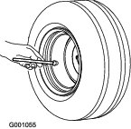
-
If the tire air pressure is not 30 psi, add air to or remove air from the tires.
Checking the PTO and Driveshaft Guards
| Maintenance Service Interval | Maintenance Procedure |
|---|---|
| Before each use or daily |
|
-
If installed to the tow vehicle, remove the driveshaft.
-
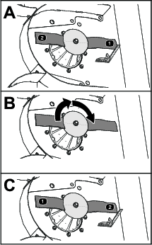
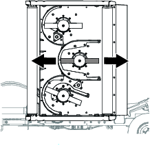
Rotate the forward half of the PTO shaft guard a full rotation (Figure 16).
Note: Clean or replace the shaft guard if it does not rotate freely.
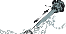
-
Move the forward half of the PTO shaft guard together and apart to ensure that they telescope freely (Figure 16).
Note: Clean or replace the shaft guard is it does not telescope freely.
-
If removed from the tow vehicle, install the driveshaft; refer to Connecting the Driveshaft to the PTO.
-
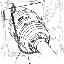
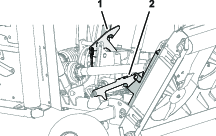
Check that the restraint chain is installed between the forward PTO shaft guard and a stationary part on the tow vehicle (Figure 17).
-
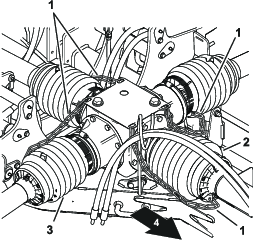
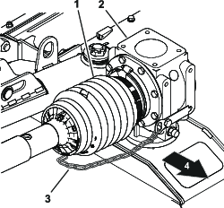
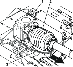
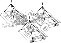
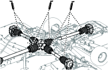
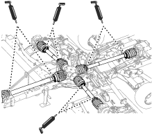
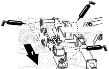
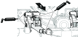
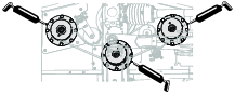
Check that the restraint chains for the driveshaft guards are connected to center gearbox and the gearboxes on each mower deck (Figure 18, Figure 19, Figure 20, and Figure 21).
-
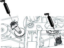
Check that the 7 hose clamps firmly secure the driveshaft guards to the center and deck gear boxes (Figure 22).
Using the Tow Bar Jack
Supporting the Mower with the Jack
-
Park the machine on a level surface, move the shift lever to the NEUTRAL position.
-
Engage the parking brake, shut off the engine, remove the key, and wait for all moving parts to stop.
-
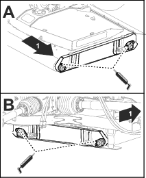
Remove the pin and rotate the tow-bar jack vertical (Figure 23).
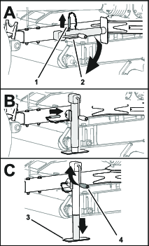
-
Align the hole in the tow bar with the hole in the jack (Figure 23).
-
Insert the pin through the holes in the tow bar and jack (Figure 23).
-
Rotate the jack handle until the jack fully supports the weight of the mower.
-
Chock both tires of the mower (Figure 24).
-
Disconnect the hydraulic hoses and the PTO driveshaft from the tow vehicle.
-
Disconnect the hitch from the tow bar.
-
Drive the tow vehicle in a straight line away from the mower.
Stowing the Jack
-
Ensure that the mower is securely attached to the tow vehicle.
-
Rotate the jack handle to fully raise the jack pad; refer to Figure 23 in Supporting the Mower with the Jack.
-
Remove the pin and rotate the tow bar jack horizontal.
-
Align the hole in the tow bar with the hole in the jack.
-
Insert the pin through the holes in the tow bar and jack.
Assembling the Mower to the Tow Vehicle
Preparing the Tow Vehicle and Mower
-
Ensure that the mower is supported with the tow-bar jack; refer to Using the Tow Bar Jack.
-
Lower the 3-point hitch; refer to the Operator’s Manual for your tow vehicle.
-
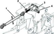
If installed, remove the lynch pin, clevis pin, and upper 3-point link from the upper-link bracket (Figure 25).
-
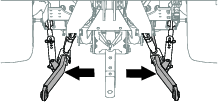
Adjust the stabilizer arms (Figure 26) outward fully; refer to the Operator’s Manual for the tow machine.
-
If your mower has a pin tow bar, remove the hairpin and hitch pin from the tow bar.
-
If your tow vehicle has a pintle hitch, open the hitch.
Selecting a Drawbar for the Mower
-
Hitch pin-hole diameter: 31.75 mm (1-1/4 inches).
-
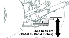
Working height: 33.4 to 40 cm (13-1/8 to 15-3/4 inches); refer to Figure 27.
-
Ensure that your drawbar does not interfere with the PTO driveshaft.
Connecting the Mower to the Tow Vehicle
-
Use jack handle to raise or lower the tow bar jack and align the tow bar to the drawbar or pintle hitch (Figure 28).
-
Fully raise the 3-point hitch; refer to the Operator’s Manual for your tow vehicle.
Note: When equipped, lock the 3-point hitch.
-
Align the drawbar or pintle hitch of the tow vehicle with the tow bar of the mower (Figure 28).
-
Move the shift lever to the NEUTRAL position, engage the parking brake, shut off the engine remove the, and wait for all moving parts to stop.
-
Secure the tow bar as follows:
-
If your mower has a pin tow bar, insert the hitch pin through the holes in the tow bar and drawbar and secure the pin with the hairpin (Figure 29).
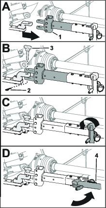
-
If your tow vehicle has a pintle hitch, close and secure the hitch.
-
-
Fully raise the jack (Figure 29).
-
Remove the pin that secures the jack to the tow bar, rotate the jack horizontal, and secure the hack to the tow bar with the pin (Figure 29).
Connecting the Driveshaft to the PTO
-
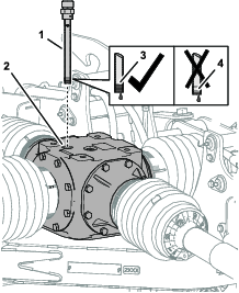
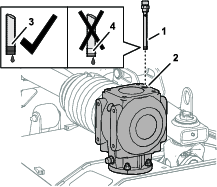
Align the quick-connect coupling of the PTO driveshaft with the output shaft of the PTO (Figure 30).
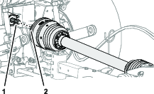
-
Pull back the lock collar of the quick-connect coupling (Figure 31).
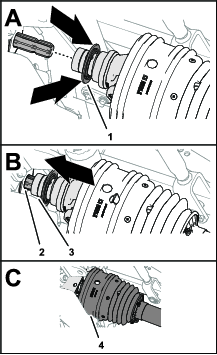
-
While pulling back the lock collar, pull the PTO driveshaft yoke forward and slip the socket of the coupling over the splines of the PTO output shaft (Figure 31).
-
Ensure that the lock at the quick-connect coupling snaps into the groove of the PTO output shaft securely.
-
Ensure that the shield is positioned over the driveshaft yoke (Figure 31).
-
Attach the restraint chain to a fixed part of the tow vehicle (Figure 32).
Important: Ensure that there is enough slack in the restraint chain so that you can turn the machine in both directions.
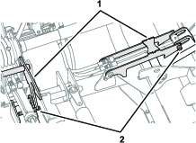
Connecting the Hydraulic Hoses
-
Identify the quick-disconnect fittings for the rear attachment-lift and lower circuits for the tow vehicle.
-
Remove the dust covers from the quick-disconnect fittings of the tow vehicle.
-
Remove the black dust cover from the quick-disconnect fitting of the cylinder-extend hose of the mower
-
Connect the quick-connect fitting cylinder extend hose to the quick-disconnect coupling rear-attachment-lower circuit (Figure 33).
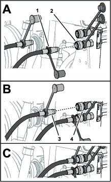
-
Remove the red dust cover from the quick-disconnect fitting of the cylinder-retract hose of the mower
-
Connect the quick-disconnect fitting of the cylinder retract hose to the quick-disconnect coupling rear-attachment-raise circuit.
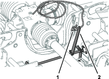
Routing the Deck-Lock Rope to the Machine
-
Route the deck-lock rope from the hose guide toward the operator’s seat (Figure 34).
Important: Ensure that you allow slack in the rope so that the mower can fully turn right and left behind the tow vehicle without adding tension to the rope, but it does not contact the PTO driveshaft.
-
Tie the rope to the fixed-chassis component of the tow vehicle such as the ROPS tube (Figure 34).
Important: Do not tie the deck-lock rope to the seat, steering wheel, or the handle of a control.
-
Remove the chocks from the mower tires.
During Operation
Note: Determine the left and right sides of the machine from the normal operating position.
During Operation Safety
-
The owner/operator can prevent and is responsible for accidents that may cause personal injury or property damage.
-
Wear appropriate clothing, including eye protection; long pants; substantial, slip-resistant footwear; and hearing protection. Tie back long hair and do not wear loose clothing or loose jewelry.
-
Do not operate the machine while ill, tired, or under the influence of alcohol or drugs.
-
Never carry passengers on the mower and keep bystanders and pets away from the machine during operation.
-
Operate the machine only in good visibility to avoid holes or hidden hazards.
-
Before you start the engine, ensure that all drives are in neutral, the PTO is disengaged, the parking brake is engaged, and you are in the operating position.
-
Keep your hands and feet away from rotating parts. Keep clear of the discharge opening at all times.
-
Look behind and down before backing up to be sure of a clear path.
-
Use care when approaching blind corners, shrubs, trees, or other objects that may obscure your vision.
-
Do not run the PTO with the decks raised above the partial up-stop position.
-
Stop the mower whenever you are not cutting grass.
-
Stop the machine, engage the parking brake, shut off the engine, remove the key, and wait for all moving parts to stop before inspecting the attachment after striking an object or if there is an abnormal vibration in the machine. Make all necessary repairs before resuming operation.
-
Slow down and use caution when making turns and crossing roads and sidewalks with the machine. Always yield the right-of-way.
-
Reduce speed on rough roads and surfaces
-
The mower is heavy. When attached to a tow vehicle, and in the raised position, the weight of the mower affects stability, braking and steering. Exercise caution when transporting between working areas.
-
Never leave a running machine unattended.
-
Before leaving the operating position (including adjusting the height of cut) do the following:
-
Ensure that the PTO is disengaged.
-
Park the machine on a level surface.
-
Engage the parking brake.
-
Lower the mower decks.
-
Shut off the engine and remove the key.
-
Wait for all moving parts to stop before leaving the machine.
-
-
Do not operate the machine when there is the risk of lightning.
-
Use accessories, attachments, and replacement parts approved by The Toro® Company only.
-
For disassembly or repair of all steel PTO driveshaft parts (tubes, bearings, joints, etc.), contact your authorized Toro distributor. Removal of components for repairs and reassembly may damage some parts if not performed with special tools by trained technicians.
-
Do not operate the mower if the PTO or driveshaft guards are missing.
-
Be careful when turning the machine so that the tow vehicle tires do not contact the PTO driveshaft.
-
Secure hydraulic hoses, electrical wiring, ropes, and other items to keep them from contacting the PTO driveshaft guard.
Slope Safety
-
Slopes are a major factor related to loss of control and rollover accidents, which can result in severe injury or death. You are responsible for safe slope operation. Operating the machine on any slope requires extra caution.
-
Review and understand the slope instructions in the manual and on the tow vehicle.
-
Evaluate the site conditions to determine if the slope is safe for machine operation, including surveying the site. Always use common sense and good judgment when performing this survey.
-
Review the slope instructions listed below for operating the machine on slopes and to determine whether you can operate the machine in the conditions on that day and at that site. Changes in the terrain can result in a change in slope operation for the machine.
-
Avoid starting, stopping, or turning the machine on slopes. Avoid making sudden changes in speed or direction. Make turns slowly and gradually.
-
Do not operate a machine under any conditions where traction, steering, or stability are in question.
-
Remove or mark obstructions such as ditches, holes, ruts, bumps, rocks, or other hidden hazards. Tall grass can hide obstructions. Uneven terrain could overturn the machine.
-
Be aware that operating the machine on wet grass, across slopes, or downhill may cause the machine to lose traction. Loss of traction to the drive wheels may result in sliding and a loss of braking and steering.
-
Use extreme caution when operating the machine near drop-offs, ditches, embankments, water hazards, or other hazards. The machine could suddenly roll over if a wheel goes over the edge or the edge caves in. Establish a safety area between the machine and any hazard.
-
Identify hazards at the base of the slope. If there are hazards, mow the slope with a power walk-behind mower.
-
If possible, keep the cutting unit(s) lowered to the ground while operating on slopes. Raising the cutting unit(s) while operating on slopes can cause the machine to become unstable.
-
Use extreme caution with other attachments. These can change the stability of the machine and cause a loss of control. Always keep the machine in gear when going down slopes. Do not coast downhill (applicable only to gear-drive units).
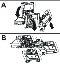
Lowering the Mower Decks from the Transport Position
-
Ensure that the PTO is in the OFF position; refer to the Operator’s Manual for your tow vehicle.
-
Move the mower to a flat area that is large enough to support the mower decks.
-
Ensure that there are no bystanders nearby.
-
Move the control for the rear attachment-circuit to the LIFT position; refer to the Operator’s Manual for your tow vehicle.
The mower decks may raise slightly and pressure on the deck locks reduces.
-
Pull and hold the deck-lock rope (Figure 35).
The deck locks release.
-
Move the control for the rear attachment-circuit to the LOWER position; refer to the Operator’s Manual for your tow vehicle.
The mower decks lower to the ground (Figure 36).
-
When the decks fully lower to the ground, release the rope and attachment control.
-
Move the control for the rear attachment-circuit to the FLOAT position; refer to the Operator’s Manual for your tow vehicle.
Raising the Mower Decks while Cutting Grass
Use this procedure to raise the mower decks slightly when turning the machines around at the end of a cutting pass.
For instruction on using the rear attachment control, refer to the Operator’s Manual for your tow vehicle.
-
Move the control for the rear attachment-circuit to the LIFT position.
The decks raise, and the lift pins contact the partial up-stop portion of the deck locks.
Note: Do not pull the deck-lock rope.
-
Turn the tow vehicle and align it for the next cutting pass.
-
Move the control for the rear attachment-circuit to the LOWER position.
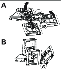
Raising the Mower Decks to the Transport Position
For instruction on using the PTO and rear attachment control, refer to the Operator’s Manual for your tow vehicle.
Note: If the rear-mower deck locks do not engage the deck pins adjust the height of the deck locks. Refer to Adjusting the Rear-Mower Deck Locks.
-
Move the mower to a flat area.
-
Shut off the PTO.
-
Pull and hold the deck-lock rope (Figure 38).
-
Move the control for the rear attachment-circuit to the RAISE position.
The mower decks raise to the TRANSPORT position (Figure 39).
-
When the decks fully raised, release the rope and attachment control.
The deck locks engage the deck pins (Figure 40).
-
Move the control for the rear attachment-circuit to the LOWER position until the deck locks support the weight of the decks.
Adjusting the Height-of-Cut
-
If the mower is installed to the tow vehicle, perform the following:
-
Ensure that the PTO is disengaged.
-
If the mower decks are in the transport position, lower the decks; refer to Lowering the Mower Decks from the Transport Position.
-
Engage the parking brake, shut off the engine, remove the key, and wait for all moving parts to stop.
-
-
Determine the height that you want to cut the grass.
-
Loosen the 4 locknuts that secure the 4 height-of-cut adjusters (Figure 41) of the mower deck.
-
Working at 1 of the deck rollers, turn the adjuster capscrew to raise or lower the mower until the pointer aligns with the grass cut height that you determined in step 2.
-
Tighten the locknuts for 2 height-of-cut adjusters.
-
Repeat steps 4 and 5 for the height-of-cut adjusters at the other roller.
-
Repeat steps 3 through 6 for the other decks.
Making a Sharp Turn
-
Shift the tow vehicle to LOW GEAR or LOW RANGE.
-
Driving the machine slowly, steer to make the sharp turn.
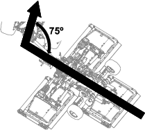
Important: Do not exceed the 75° maximum tow vehicle to mower angle.
-
As you turn, check to ensure clearance between the tire of the tow vehicle and the parts of the mower (Figure 43).
Note: If the tire is too close to the mower, turn more gradually.
After Operation
After Operation Safety
-
Park the machine on a level surface; engage the parking brake; shut off the engine; remove the key; and wait for all movement to stop before leaving the machine.
-
Do not step on, over or under the driveshaft.
-
Do not use the restrain chain of the PTO-shaft guard to support the shaft when transporting or storing the mower.
-
Do not rest the PTO shaft on the ground.
-
Do not allow the PTO-shaft guards to pull apart.
-
Keep all parts of the machine in good working condition and all hardware tightened.
-
Replace all worn, damaged, or missing decals.
Clean and Inspect
| Maintenance Service Interval | Maintenance Procedure |
|---|---|
| After each use |
|
Raise the mower decks and thoroughly wash them.
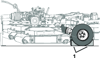
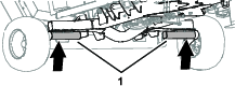
Tie-Down Points
Transporting the Machine
Important: Raise and latch the decks before loading the mower on to or off from the trailer.
-
Use care when loading or unloading the machine into a trailer or a truck.
-
Use full-width ramps for loading the machine into a trailer or a truck.
Refer to Operator’s Manual for your tow chassis and tow vehicle the tie-down locations of the machine.
-
Drive the tow vehicle up the ramp.
-
Shut off the engine, remove the key, and engage the parking brake.
-
Lower the jack.
-
Tie down the machine near the wheels with straps, chains, or cables.
Note: Refer to local regulations for tie-down requirements.
-
Secure blocks at the wheels of the machine to the bed of the trailer or truck.
-
Ensure that the PTO driveshaft is coupled to a tow vehicle or secured to the tow bar of the mower.
Maintenance
Caution
If you leave the key in the switch, someone could accidently start the engine and seriously injure you or other bystanders.
Remove the key from the switch before you perform any maintenance.
Warning
If the mower decks are raised but not latched, the decks could lower unexpectedly and seriously injure you or other bystanders.
Fully raise all decks and ensure the pins on all lift arms engage the latches.
Recommended Maintenance Schedule(s)
| Maintenance Service Interval | Maintenance Procedure |
|---|---|
| After the first 50 hours |
|
| Before each use or daily |
|
| After each use |
|
| Every 50 hours |
|
| Every 500 hours |
|
| Before storage |
|
| Yearly |
|
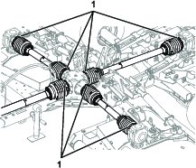
Lifting the Mower
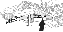
-
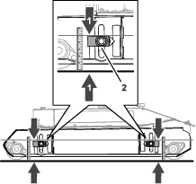
Lift the mower at the axle halves as shown in Figure 45.
-
Use jack stands to support the mower.
Accessing the Mower Decks
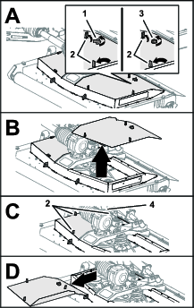
Removing the Deck Covers
Installing the Deck Covers
-
Align the latches of the mower-deck cover with the holes in the mower deck (Figure 47).
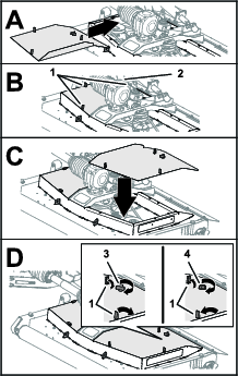
-
Assemble the deck cover to the mower deck (Figure 47).
-
Secure the cover (Figure 47) as follows:
-
Non-CE mowers: thread the knob through the cover and into the mower deck, and tighten the knob.
-
CE mowers: thread the bolt into the mower deck, and tighten the bolt.
-
-
Secure the 3 latches of the cover to the mower deck (Figure 47).
-
Repeat steps 1 through 4 for the other covers that you removed (Figure 47).
Lubrication
Grease Specification
No. 2 lithium base grease
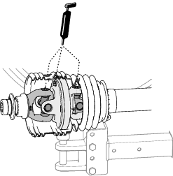
Greasing the PTO Shaft Constant Velocity Joint
| Maintenance Service Interval | Maintenance Procedure |
|---|---|
| Before each use or daily |
|
Apply the specified grease to the 3 grease fittings at the forward end of the PTO driveshaft (Figure 48).
Greasing the Telescoping Driveshaft Joints
| Maintenance Service Interval | Maintenance Procedure |
|---|---|
| Every 50 hours |
|
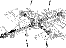
Greasing the Driveshaft U-Joints
| Maintenance Service Interval | Maintenance Procedure |
|---|---|
| Every 50 hours |
|
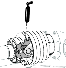
Apply the specified grease to the 7 fitting for the driveshaft U-joints as shown in Figure 50.
Greasing the Driveshaft Guard-Slip Joints
| Maintenance Service Interval | Maintenance Procedure |
|---|---|
| Every 50 hours |
|
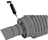
Apply the specified grease to the 6 grease fittings for the driveshaft guard-slip joints as shown in Figure 51.
Greasing the Lift Arms, Hydraulic Cylinders, Latches, and Impact Struts
| Maintenance Service Interval | Maintenance Procedure |
|---|---|
| Every 50 hours |
|
Greasing the Spindles
| Maintenance Service Interval | Maintenance Procedure |
|---|---|
| Every 50 hours |
|
Apply the specified grease to the grease fitting at the 3 spindles at each mower deck (Figure 53).
Greasing the Belt Tensioners
| Maintenance Service Interval | Maintenance Procedure |
|---|---|
| Every 50 hours |
|
Apply the specified grease to the grease fittings at the 2 belt tensioners of each mower deck.
Greasing the Deck Rollers
| Maintenance Service Interval | Maintenance Procedure |
|---|---|
| Every 50 hours |
|
Servicing the Gearboxes
Customer supplied material: PTFE thread sealant and a small hand pump.
Gearbox Fluid Specification
-
Toro Premium Tractor fluid
-
Mobilfluid™ 424 tractor hydraulic fluid
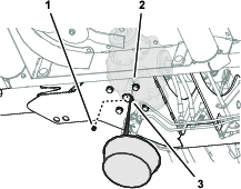
Checking the Gearbox Fluid Level
| Maintenance Service Interval | Maintenance Procedure |
|---|---|
| Every 50 hours |
|
-
Remove the dipstick from the dipstick port at the top of the center gearbox (Figure 57 or Figure 58).
-
Check the fluid level indicated on the dipstick (Figure 57 or Figure 58).
The fluid level should indicate between the full and add marks of the dipstick.
Note: Add lubricant as needed to raise the level between the full and add marks; refer to Filling the Deck Gearbox or Filling the Center Gearbox.
-
Clean the threads of the dipstick and fill plug and apply PTFE thread sealant to the threads.
-
Thread the dipstick into the fill port and tighten the dipstick (Figure 57 or Figure 58).
-
Repeat steps 1 through 4 for the deck gearboxes.
Changing the Center Gear Box Lubricant
| Maintenance Service Interval | Maintenance Procedure |
|---|---|
| After the first 50 hours |
|
| Yearly |
|
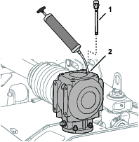
Draining the Center Gearbox
-
Working through the access hole at the bottom-frame plate of the mower, align a drain pan under the hole (Figure 60).
-
Remove the socket-drain plug from the drain port of the center gearbox and allow the lubricant to drain completely (Figure 60).
-
Clean the threads of the drain plug and apply PTFE thread sealant to the threads.
-
Assemble the drain plug into the drain port and tighten the plug.
Filling the Center Gearbox
Center gearbox fluid capacity: 2.48 L (84 fl oz)
-
Remove the dipstick from the dipstick port at the top of the center gearbox and wipe clean the dipstick (Figure 61).
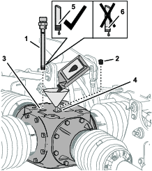
-
Remove the fill plug from the fill port at the top of the gearbox (Figure 61).
-
Add 2.48 L (84 fl oz) of the specified gear lubricant to the gearbox through the fill port (Figure 61).
-
Thread the dipstick into the port, remove the dipstick, and check that the lubricant level (Figure 61).
The fluid level should indicate between the full and add marks of the dipstick.
Note: Add lubricant as needed to raise the level between the full and add marks.
-
Clean the threads of the dipstick and fill plug and apply PTFE thread sealant to the threads.
-
Thread the dipstick into the fill port and tighten the dipstick (Figure 61).
-
Assemble the fill plug into the fill port and tighten the plug (Figure 61).
Changing the Deck Gearbox Lubricant
| Maintenance Service Interval | Maintenance Procedure |
|---|---|
| After the first 50 hours |
|
| Yearly |
|
Emptying the Deck Gearbox
Filling the Deck Gearbox
Deck gearbox fluid capacity: 1.06 L (36 fl oz)
-
Add 1.06 L (36 fl oz) of the specified gear lubricant to the gearbox through the dipstick port (Figure 63).
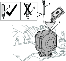
-
Thread the dipstick into the port, remove the dipstick, and check that the lubricant level (Figure 63).
The fluid level should indicate between the full and add marks of the dipstick.
Note: Add lubricant as needed to raise the level between the full and add marks.
-
Clean the threads of the dipstick and apply PTFE thread sealant to the threads.
-
Thread the dipstick into the fill port and tighten the dipstick (Figure 63).
-
Repeat steps and1 through 4 for the other deck gearboxes.
Checking the Mower Belts
| Maintenance Service Interval | Maintenance Procedure |
|---|---|
| After the first 50 hours |
|
The blade drive belts, tensioned by the spring loaded idler pulleys, are durable. However, after many hours of use, the belts will show signs of wear. Signs of a worn belt include: squealing when belt is rotating, the mower blades slip when cutting grass, the belt has frayed edges, the belt has burn marks and cracks, and poor quality of cut. Replace the belts if you notice any of these conditions.
-
Remove the deck covers; refer to Removing the Deck Covers.
-
Check the short and long belt for signs of damage or excessive wear.
Replace damaged or worn belts; refer to Replacing the Mower Belts.
-
Install the deck covers; refer to Installing the Deck Covers.
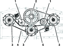
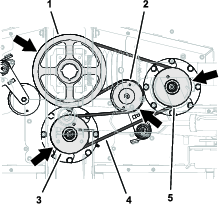
Replacing the Mower Belts
Note: You must remove the long belt to replace the short belt.
Removing the Long Belt
-
Remove the belt covers; refer to Removing the Deck Covers
-
Use a breaker bar or similar tool to rotate the belt tensioner for the long belt counterclockwise and slip the belt off the tensioner pulley (Figure 65).
-
Slip the long belt off the drive pulley, center-spindle pulley, and right-spindle pulley (Figure 65).
-
Remove the belt from the mower.
Note: You may need to rotate the belt while removing it from the center-spindle pulley.
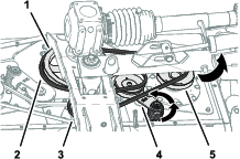
Removing the Short Belt
-
Remove the belt covers; refer to Removing the Deck Covers.
-
If installed, remove the long belt; refer to Removing the Long Belt.
-
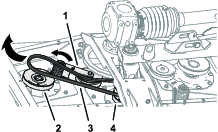
Use a breaker bar or similar tool to rotate the belt tensioner for the short belt counterclockwise and slip the belt off the tensioner pulley (Figure 66).
-
Slip the short belt off the drive pulley, center-spindle pulley, and right-spindle pulley
-
Remove the belt from the mower.
Note: You may need to rotate the belt while removing it from the center-spindle pulley.
Installing the Short Belt
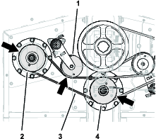
Installing the Long Belt
-
Route the long belt around the drive pulley, upper groove of the center-spindle pulley, and right-spindle pulley (Figure 68).
-
Use a breaker bar or similar tool to rotate the belt tensioner counterclockwise and slip the belt over the tensioner pulley (Figure 68).
-
Install the deck covers; refer to Installing the Deck Covers.
Servicing the Blades
Maintain sharp blades throughout the cutting season because sharp blades cut cleanly without tearing or shredding the grass blades. Tearing and shredding turns grass brown at the edges, which slows growth and increases the chance of disease.
Check the blades daily for sharpness, and for any wear or damage. Sharpen the blades as necessary. If a blade is damaged or worn, replace it immediately with a genuine Toro replacement blade.
Danger
The mower blades are sharp and can injure you.
Wear heavy leather or cut resistant gloves when servicing with the blades.
Danger
A worn or damaged blade can break, and a piece of the blade could be thrown toward you or a bystander, resulting in serious personal injury or death.
-
Inspect the blade periodically for wear or damage.
-
Replace a worn or damaged blade.
Preparing to Service the Mower Blades
Note: You need the mower installed to the tow vehicle when servicing the mower blades.
-
Disengage the PTO, move the machine to a level surface, and engage the parking brake.
-
Raise and latch the mower decks, shut off the engine, and remove the key (Figure 69).
Checking for Bent Mower Blades
-
Align the mower blade as shown in Figure 70.
-
Clean the bottom of the mower deck at the area adjacent to the cutting edge at the rear of the blade (Figure 71).
-
Use a combination square to measure the distance between the clean area of the deck and the tip of the cutting edge (Figure 72).
Record your measurement .
-
Rotate the blade 180° (Figure 72).
-
Measure the distance between the clean area on the deck and the tip of the cutting edge (Figure 72).
Record your measurement .
The difference between measurements that you observed in steps 4 and 6 exceed 3 mm (1/8 inch), the blade is bent, and you must replace the it; refer to Removing the Blades and Installing the Blades
-
Repeat steps 3 through 5 for the other blades of the mower deck or steps 1 through 6 for the other decks.
Inspecting the Blades
| Maintenance Service Interval | Maintenance Procedure |
|---|---|
| Before each use or daily |
|
-
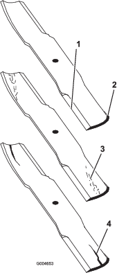
Inspect the cutting edges (Figure 73). If the edges are not sharp or have nicks, remove and sharpen the blades. Refer to Sharpening the Blades.
-
Inspect the blades, especially the sail area (Figure 73). If you notice any damage, wear, or a slot forming in this area (Figure 73), immediately install a new blade.
Danger
If you allow the blade to wear, a slot will form between the sail and flat part of the blade. Eventually a piece of the blade may break off and be thrown from under the housing, possibly resulting in serious injury or death to you or bystanders.
-
Inspect the blade periodically for wear or damage.
-
Never try to straighten a blade that is bent or weld a broken or cracked blade.
-
Replace a worn or damaged blade.
-
Removing the Blades
Blades must be replaced if a solid object is hit, if the blade is out of balance or is bent. To ensure optimum performance and continued safety conformance of the machine, use genuine Toro replacement blades. Replacement blades made by other manufacturers may result in non-conformance with safety standards.
Warning
Contact with a sharp blade can cause serious injury.
Wear gloves or wrap sharp edges of the blade with a rag.
Sharpening the Blades
Warning
When sharpening blade, pieces of blade could be thrown and cause serious injury.
Wear proper eye protection when sharpening blades.
-
Sharpen the cutting edge at both ends of the blade (Figure 75).
Note: Maintain the original angle. The blade retains its balance if the same amount of material is removed from both cutting edges.
-
Check the balance of the blade by putting it on a blade balancer (Figure 76).
Note: If the blade stays in a horizontal position, the blade is balanced and can be used. If the blade is not balanced, file some metal off the end of the sail area only (Figure 77). Repeat this procedure until the blade is balanced.

Installing the Blades
-
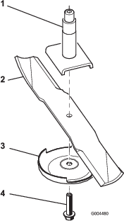
Install the blade onto the spindle shaft (Figure 77).
Important: The curved part of the blade must be pointing upward toward the inside of the mower to ensure proper cutting.
-
Install the anti-scalp plate and blade bolt (Figure 77).
Important: The blade bolts have left-hand threads.
-
Torque the blade bolt to 115 to 150 N∙m (85 to 110 ft-lb).
Adjusting the Mower Pitch
The factory presets the pitch of the mower deck so that back of the deck is higher than the front.
Preparing the Adjust Mower Pitch
Customer provided material: a wood block 51 mm (2 inch)
-
For each mower deck that you are adjusting mower pitch, align the center mower blade shown in Figure 78.
-
Lower the mower decks to the ground.
Leveling the Deck
Setting the Deck Pitch
Customer provided material: wood spacer block 51 mm (2 inches)
-
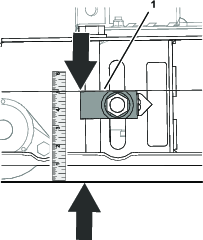
Working at the back of the mower deck, lift the rear flap and align the wood block 51 mm (2 inches) between the rear end of the center mower blade and the ground (Figure 80).
You should feel slight drag as you slip the block between the blade and the ground.
-
If there is too much clearance between the blade and the ground, use the 4 height-of-cut adjusters to lower the deck.
-
If you cannot slip the wood block between the blade and the ground, use the 4 height-of-cut adjusters to raise the deck.
-
-
Measure the distance between top of adjuster block to the ground (Figure 81).
Rotate the height-of-cut adjuster until you achieve the following results:
-
The height-of-cut block to the ground measurement the same at all 4 locations.
-
The wood block is a slip fit between the center mower blade and the ground.
-
-
Loosen the 2 socket-head screws that secure the pointer to the height-of-cut adjuster block, align the pointer to the 51 mm (2 inches) mark on the decal, and tighten the screws (Figure 82).
-
Repeat step 3 at the other height-of-cut adjusters.
-
At the rear roller, raise the left and right height of cut adjusters to the 57 mm (2-1/4 inches) mark on the decal (Figure 83).
-
Loosen the socket-head screws that secure the 2 pointers to the height-of-cut adjuster block, align the pointers to the 51 mm (2 inches) mark on the decal, and tighten the screws (Figure 84).
-
Torque the 4 nuts that secure the 4 height-of-cut adjuster blocks (Figure 82 and Figure 84) for the front and rear rollers to 322 to 396 N∙m (238 to 292 ft-lb).
Adjusting the Rear-Mower Deck Locks
Adjust the rear-mower deck locks when the mower deck does not correctly latch the deck pins (Figure 40).
Storage
Storing the Machine
At the end of the mowing season or when the mower is stored for an extended period, carry out the following preventative maintenance:
-
Park the machine on a level surface; engage the parking brake; shut off the engine; remove the key; and wait for all movement to stop before leaving the machine.
-
Clean off any dirt or grease that may have accumulated on the machine or any of the moving parts.
-
Lubricate all grease fittings.
-
Touch up paint any other scratches on the painted surfaces.
-
Replace any missing or damaged decals.
-
When possible, store the mower inside a dry, secure building. If inside storage is not available, cover the machine with a heavy sheet or tarpaulin and secure it tightly.