| Maintenance Service Interval | Maintenance Procedure |
|---|---|
| Before each use or daily |
|
Introduction
This rotary-blade lawn mower is intended to be used by residential homeowners or professional, hired operators. It is designed primarily for cutting grass on well-maintained lawns on residential or commercial properties. Using this product for purposes other than its intended use could prove dangerous to you and bystanders.
Read this information carefully to learn how to operate and maintain your product properly and to avoid injury and product damage. You are responsible for operating the product properly and safely.
Visit www.Toro.com for more information, including safety tips, training materials, accessory information, help finding a dealer, or to register your product.
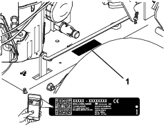
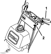
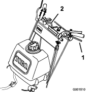
Whenever you need service, genuine Toro parts, or additional information, contact an Authorized Service Dealer or Toro Customer Service and have the model and serial numbers of your product ready. Figure 1 identifies the location of the model and serial numbers on the product. Write the numbers in the space provided.
Important: With your mobile device, you can scan the QR code on the serial number decal (if equipped) to access warranty, parts, and other product information.
This manual uses 2 words to highlight information. Important calls attention to special mechanical information and Note emphasizes general information worthy of special attention.
The safety-alert symbol (Figure 2) appears both in this manual and on the machine to identify important safety messages that you must follow to avoid accidents. This symbol will appear with the word Danger, Warning, or Caution.
-
Danger indicates an imminently hazardous situation which, if not avoided, will result in death or serious injury.
-
Warning indicates a potentially hazardous situation which, if not avoided, could result in death or serious injury.
-
Caution indicates a potentially hazardous situation which, if not avoided, may result in minor or moderate injury.

This product complies with all relevant European directives; for details, please see the separate product specific Declaration of Conformity (DOC) sheet.
Safety
This machine has been designed in accordance with EN ISO 5395.
General Safety
This product is capable of amputating hands and feet and of throwing objects. Always follow all safety instructions to avoid serious personal injury.
-
Read, understand, and follow the instructions and warnings in this Operator’s Manual and on the machine and attachments before starting the engine.
-
Do not put your hands or feet near moving parts of or under the machine. Keep clear of any discharge opening.
-
Do not operate the machine without all guards and other safety protective devices in place and functioning properly on the machine.
-
Keep bystanders and children out of the operating area. Do not allow children to operate the machine. Allow only people who are responsible, trained, familiar with the instructions, and physically capable to operate the machine.
-
Stop the machine, shut off the engine, remove the ignition key (if equipped), and wait for all moving parts to stop before servicing, fueling, or unclogging the machine.
Improperly using or maintaining this machine can result in injury.
To reduce the potential for injury, comply with these safety instructions
and always pay attention to the safety-alert symbol , which means
Caution, Warning, or Danger—personal safety instruction. Failure
to comply with these instructions may result in personal injury or
death.
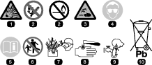
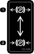
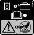
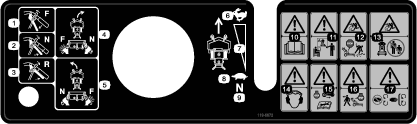
Safety and Instructional Decals
|
Safety decals and instructions are easily visible to the operator and are located near any area of potential danger. Keep safety signs clear and visible, replace any decal that is damaged or missing. |
.png)


Setup
Note: Determine the left and right sides of the machine from the normal operating position.
Checking the Fluids and Tire Pressure
-
Before you start the engine and use the machine, check the oil level in the engine crankcase; refer to Checking the Engine-Oil Level.
-
Check the grease for the machine and mower deck.
Installing the Wheel Kit
Parts needed for this procedure:
| Wheel Kit (sold separately) | 1 |
Refer to the Installation Instructions for the wheel kit.
Installing the Mower Deck
Parts needed for this procedure:
| Mower deck (sold separately) | 1 |
Refer to the Operator’s Manual for the mower deck.
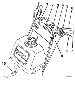
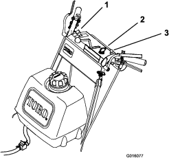
Product Overview
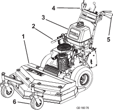
Become familiar with all the controls (Figure 4) before you start the engine and operate the machine.
Control Panel
Throttle Control
The throttle controls the engine speed, and it has a continuous-variable setting from the SLOW to FAST position (Figure 4).
Operator-Presence Control (OPC) Levers
When you squeeze the OPC levers against the handles, the OPC system senses that you are in the normal operating position.
When you release the OPC levers, the OPC system senses that you left the normal operating position, and the system shuts off the engine if either the speed-control lever is not in the NEUTRAL position or the blade-control switch (power takeoff) is engaged.
Blade-Control Switch (PTO)
Use the blade-control switch (PTO), with the OPC levers pressed against the handles, to engage and disengage the drive belt to drive the mower blades.
Pull the switch up to engage the blades and push it down to disengage the blades.
Key Switch
The key switch, used to start and shut off the engine, has 3 positions: OFF, RUN, and START.
Speed-Control Lever
This machine has a variable speed control with a NEUTRAL position. This controls how fast the machine travels.
Neutral Lock
Squeeze the drive levers back until you feel an increase in force, then move the locks to rearward to the NEUTRAL-LOCK position.
Fuel-Shutoff Valve
Close the fuel-shutoff valve when transporting or storing the machine.
Choke
Use the choke to start a cold engine.
Note: Specifications and design are subject to change without notice.
| Width | 89 cm (35 inches) |
| Length | 203 cm (80 inches) |
| Height | 112 cm (44 inches) |
| Weight | 231 kg (509 lb) |
Attachments/Accessories
A selection of Toro approved attachments and accessories is available for use with the machine to enhance and expand its capabilities. Contact your Authorized Service Dealer or authorized Toro distributor or go to www.Toro.com for a list of all approved attachments and accessories.
To ensure optimum performance and continued safety certification of the machine, use only genuine Toro replacement parts and accessories. Replacement parts and accessories made by other manufacturers could be dangerous, and such use could void the product warranty.
Operation
Before Operation
Before Operation Safety
General Safety
-
Do not allow children or untrained people to operate or service the machine. Local regulations may restrict the age of the operator. The owner is responsible for training all operators and mechanics.
-
Become familiar with the safe operation of the equipment, operator controls, and safety signs.
-
Always shut off the machine, remove the ignition key (if equipped), wait for all moving parts to stop, and allow the machine to cool before adjusting, servicing, cleaning, or storing it.
-
Know how to stop the machine and shut off the engine quickly.
-
Check that operator-presence controls, safety switches, and safety protective devices are attached and functioning properly. Do not operate the machine unless they are functioning properly.
-
Inspect the area where you will use the machine, and remove all objects that could interfere with the operation of the machine or that the machine could throw.
-
Evaluate the terrain to determine what accessories and attachments are needed to properly and safely perform the job.
-
Before using, always visually inspect to see that the blades, blade bolts and mower deck are not worn or damaged. Replace worn or damaged blades and bolts in sets to preserve balance.
Fuel Safety
-
Use extreme care in handling fuel. It is flammable and its vapors are explosive.
-
Extinguish all cigarettes, cigars, pipes, and other sources of ignition.
-
Use only an approved fuel container.
-
Do not remove the fuel cap or add fuel to the tank while the engine is running or hot.
-
Do not add or drain fuel in an enclosed space.
-
Do not store the machine or fuel container where there is an open flame, spark, or pilot light, such as on a water heater or other appliance.
-
If you spill fuel, do not attempt to start the engine; avoid creating a source of ignition until the fuel vapors have dissipated.
-
Do not fill containers inside a vehicle or on a truck or trailer bed with a plastic liner. Always place containers on the ground, away from the vehicle before filling.
-
Remove equipment from the truck or trailer and refuel it on the ground. If this is not possible, refuel such equipment with a portable container rather than from a fuel-dispenser nozzle.
-
Keep the nozzle in contact with the rim of the fuel tank or container opening at all times until fueling is complete.
Adding Fuel
Recommended Fuel
-
For best results, use only clean, fresh (less than 30 days old), unleaded gasoline with an octane rating of 87 or higher ((R+M)/2 rating method).
-
Ethanol: Gasoline with up to 10% ethanol (gasohol) or 15% MTBE (methyl tertiary butyl ether) by volume is acceptable. Ethanol and MTBE are not the same. Gasoline with 15% ethanol (E15) by volume is not approved for use. Never use gasoline that contains more than 10% ethanol by volume, such as E15 (contains 15% ethanol), E20 (contains 20% ethanol), or E85 (contains up to 85% ethanol). Using unapproved gasoline may cause performance problems and/or engine damage which may not be covered under warranty.
-
Do not use gasoline containing methanol.
-
Do not store fuel either in the fuel tank or fuel containers over the winter unless you use a fuel stabilizer.
-
Do not add oil to gasoline.
Using Stabilizer/Conditioner
Use a fuel stabilizer/conditioner in the machine to provide the following benefits:
-
Keeps fuel fresh longer when used as directed by the fuel-stabilizer manufacturer
-
Cleans the engine while it runs
-
Eliminates gum-like varnish buildup in the fuel system, which causes hard starting
Important: Do not use fuel additives containing methanol or ethanol.
Add the correct amount of fuel stabilizer/conditioner to the fuel.
Note: A fuel stabilizer/conditioner is most effective when mixed with fresh fuel. To minimize the chance of varnish deposits in the fuel system, use fuel stabilizer at all times.
Filling the Fuel Tank
-
Park the machine on a level surface.
-
Engage the parking brake.
-
Shut off the engine and remove the key.
-
Clean around the fuel-tank cap.
-
Fill the fuel tank to the bottom of the filler neck.
Note: Do not fill the fuel tank completely full. The empty space in the tank allows the fuel to expand.
Using the Safety-Interlock System
Warning
If the safety-interlock switches are disconnected or damaged, the machine could operate unexpectedly, causing personal injury.
-
Do not tamper with the interlock switches.
-
Check the operation of the interlock switches daily and replace any damaged switches before operating the machine.
Understanding the Safety-Interlock System
The safety-interlock system is designed to prevent the engine from starting unless:
-
The blade-control switch (PTO) is disengaged.
-
The speed-control lever is in the NEUTRAL position.
The safety-interlock system is designed to shut off the engine when:
-
The operator-presence control (OPC) levers are released with the machine engaged and/or the speed control is not in the NEUTRAL position.
-
The speed-control lever is shifted out of the NEUTRAL position without holding the OPC levers or with the brake engaged.
-
The blade-control switch (PTO) is engaged without holding the OPC levers.
Testing the Safety-Interlock System
Test the safety-interlock system each time before you use the machine. If the safety system does not operate as described, have an Authorized Service Dealer repair the safety system immediately.
-
Engage the neutral locks and move the speed-control lever to the NEUTRAL position.
-
Start the engine.
-
Without holding the operator-presence control (OPC) levers, engage the blade-control switch (PTO).
The engine should shut off.
-
Disengage the blade-control switch (PTO) .
-
With the engine running, hold down the OPC levers and engage the blade-control switch (PTO).
The drive belt should engage and the mower blades should rotate.
-
Release the OPC levers.
The engine should shut off.
-
With the engine running, move the speed-control lever forward, then release the OPC levers.
The engine should shut off.
If all the above conditions are not met, have an Authorized Service Dealer repair the safety system immediately.
Performing Daily Maintenance
Before starting the machine each day, perform the Each Use/Daily procedures listed in .
During Operation
During Operation Safety
General Safety
-
The owner/operator can prevent and is responsible for accidents that may cause personal injury or property damage.
-
Wear appropriate clothing, including eye protection; long pants; substantial, slip-resistant footwear; and hearing protection. Tie back long hair and do not wear loose clothing or loose jewelry.
-
Use your full attention while operating the machine. Do not engage in any activity that causes distractions; otherwise, injury or property damage may occur.
-
Do not operate the machine while ill, tired, or under the influence of alcohol or drugs.
-
Before you start the engine, ensure that all drives are in neutral, the parking brake is engaged, and you are in the operating position.
-
Keep bystanders out of the operating area. Stop the machine if anyone enters the area.
-
Operate the machine only in good visibility and appropriate weather conditions. Do not operate the machine when there is the risk of lightning.
-
Wet grass or leaves can cause serious injury if you slip and contact the blade. Avoid mowing in wet conditions.
-
Keep your hands and feet away from the cutting unit.
-
Look behind and down before backing up to be sure of a clear path.
-
Use extreme care when approaching blind corners, shrubs, trees, or other objects that may block your view.
-
Disengage the drive to the cutting unit and engage the parking brake before adjusting the height of cut.
-
Operate the engine only in well-ventilated areas. Exhaust gases contain carbon monoxide, which is lethal if inhaled.
-
Do not leave a running machine unattended.
-
Before leaving the operating position (including to empty the catchers or to unclog the cutting units), do the following:
-
Park the machine on level ground.
-
Disengage the cutting unit and lower the attachments.
-
Engage the parking brake.
-
Shut off the machine and remove the ignition key (if equipped).
-
Wait for all moving parts to stop.
-
Shut off the machine and disengage the drive to the cutting unit in the following situations:
-
Before fueling
-
Before clearing blockages
-
Before checking, cleaning, or maintaining the cutting unit
-
After striking a foreign object or if an abnormal vibration occurs. Inspect the cutting unit for damage and make repairs before starting and operating the machine
-
Before leaving the operating position
-
-
Use only accessories and attachments approved by The Toro® Company.
-
Be sure of your footing while using this machine, especially when backing up. Walk; do not run.
-
Never operate with the discharge deflector raised, removed or altered, unless you are using a grass catcher.
-
Never carry passengers on the machine.
-
Do not direct the discharge material toward anyone. Avoid discharging material against a wall or obstruction; material may ricochet toward you. Stop the blade(s) when crossing gravel surfaces.
-
Start the engine carefully according to instructions and with your feet well away from the blade(s) and not in front of the discharge chute.
-
Use extreme caution when reversing or pulling the machine toward you.
-
Stop the blade if you must transport the machine to and from the mowing area and when crossing surfaces other than grass.
-
Slope Safety
-
Slopes are a major factor related to loss of control and rollover accidents, which can result in severe injury or death. You are responsible for safe slope operation. Operating the machine on any slope requires extra caution. Before using the machine on a slope, do the following:
-
Review and understand the slope instructions in the manual and on the machine.
-
Evaluate the site conditions of the day to determine if the slope is safe for machine operation. Use common sense and good judgment when performing this evaluation. Changes in the terrain, such as moisture, can quickly affect the operation of the machine on a slope.
-
-
Operate across slopes, never up and down. Avoid operation on excessively steep or wet slopes. Poor footing could cause a slip-and-fall accident.
-
Identify hazards at the base of the slope. Do not operate the machine near drop-offs, ditches, embankments, water, or other hazards. The machine could suddenly roll over if a wheel goes over the edge or the edge collapses. Keep a safe distance between the machine and any hazard. Use a handheld tool to operate in these areas.
-
Avoid starting, stopping, or turning the machine on slopes. Avoid making sudden changes in speed or direction; turn slowly and gradually.
-
Do not operate a machine under any conditions where traction, steering or stability is in question. Be aware that operating the machine on wet grass, across slopes or downhill may cause the machine to lose traction. Loss of traction to the drive wheels may result in sliding and a loss of braking and steering. The machine can slide even if the drive wheels are stopped.
-
Remove or mark obstacles such as ditches, holes, ruts, bumps, rocks, or other hidden hazards. Tall grass can hide obstacles. Uneven terrain could overturn the machine.
-
If you lose control of the machine, step away from the direction of travel of the machine.
-
Always keep the machine in gear when going down slopes. Do not coast downhill (applicable only to gear-drive units).
Operating the Parking Brake
Always engage the parking brake when you stop the machine or leave it unattended.
Engaging the Parking Brake
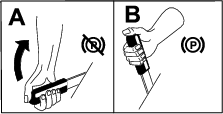
Disengaging the Parking Brake
Starting the Engine
-
Connect the wires to the spark plugs.
-
Open the fuel valve.
-
Disengage the blade-control knob (PTO) and move the speed-control lever to the NEUTRAL position.
-
Move the drive levers to the NEUTRAL position and engage the neutral locks.
-
Engage the parking brake.
-
Turn the key to the RUN position (Figure 4).
-
Move the throttle control midway between the FAST and SLOW positions.
Note: If the engine is warm, move the throttle control to the FAST position.
-
Engage the choke.
Note: A warm or hot engine usually does not require any choking.
-
Turn the key to the START position to energize the starter. When the engine starts, release the key.
Important: Do not engage the starter for more than 5 seconds at a time. If the engine fails to start, allow for a 15 second cool-down period between attempts. Failure to follow these instructions can burn out the starter motor.
-
As the engine warms up, disengage the choke and move the throttle control to the FAST position.
Shutting Off the Engine
Important: In an emergency, you can shut off the engine immediately by turning the key to the OFF position.
-
Park the machine on a level surface.
-
Move the drive levers to the NEUTRAL position and engage the neutral locks.
-
Move the throttle lever to the SLOW (Figure 7).
-
Disengage the blade-control knob (PTO) and move the speed-control lever to the NEUTRAL position.
-
Let the engine idle for 30 to 60 seconds
-
Turn the key to the OFF position.
-
Engage the parking brake and remove the key.
Important: Close the fuel-shutoff valve before transporting or the storing the machine to prevent fuel leakage.
Operating the Neutral Locks
Always engage the neutral locks when you stop the machine. Engage the parking brake if you leave the machine unattended.
Engaging the Neutral Locks
-
Squeeze the drive levers rearward until you feel an increase in force.
-
Place your thumbs on the upper part of the locks and move them rearward into the NEUTRAL position (Figure 8).
Disengaging the Neutral Locks
-
Squeeze the drive levers rearward until you feel an increase in force.
-
Place your thumbs on the upper part of the locks and move them forward until the pins are in the forward slot (Figure 9).
Operating the Blade-Control Switch (PTO)
The blade-control switch (PTO), used in conjunction with the operator-presence control, engages and disengages power to the mower blades.
Engaging the Mower Blades
-
Squeeze the operator-presence control levers against the handle grips (Figure 10).
-
Pull the blade-control switch (PTO) up and hold the operator-presence control levers against the handle grip (Figure 10).
Note: If you release the operator-presence control levers, start the engine and repeat this procedure to engage the mower blades.
Disengaging the Mower Blades
Disengage the mower blades 1 of the following ways:
-
Push the blade-control switch (PTO) down to the OFF position.
-
Release the operator-presence control levers with the blade-control lever engaged.
Driving the Machine
The throttle control regulates the engine speed (rpm). Move the throttle control to the FAST position for the best mowing performance.
Driving Forward
-
Disengage the parking brake.
-
Move the speed-control lever to the desired speed.
-
Disengage the neutral lock.
-
Slowly release the drive levers to move forward (Figure 11).
To drive straight, release the drive levers equally (Figure 11).
To turn, squeeze the drive lever on the side of the direction in which you want to turn (Figure 11).
Driving Backward
Slowly squeeze the drive levers to the handle to move rearward (Figure 11).
Bringing the Machine to Neutral
Always engage the neutral lock and parking brake when you stop the machine.
-
Squeeze the drive levers to the NEUTRAL position.
-
Engage the neutral locks. Refer to Engaging the Neutral Locks.
-
Move the speed-control lever to the NEUTRAL position.
Adjusting the Height of Cut
Refer to the Operator’s Manual for the mower deck.
After Operation
After Operation Safety
General Safety
-
Always shut off the machine, remove the ignition key (if equipped), wait for all moving parts to stop, and allow the machine to cool before adjusting, servicing, cleaning, or storing it.
-
Clean grass and debris from the machine to help prevent fires. Clean up oil or fuel spills.
-
Never store the machine or fuel container where there is an open flame, spark, or pilot light, such as on a water heater or on other appliances.
-
Use full-width ramps for loading the machine into a trailer or truck.
-
Tie the machine down securely using straps, chains, cable, or ropes. Direct both front and rear straps down and outward from the machine.
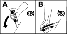
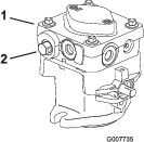
Pushing the Machine by Hand
The bypass valves allow you to push the machine by hand without the engine running.
Important: Always push the machine by hand. Never tow the machine, because hydraulic damage may occur.
-
Park the machine on a level surface, disengage the PTO, and engage the parking brake.
-
Shut off the engine, remove the key, and wait for all moving parts to stop before leaving the operating position.
-
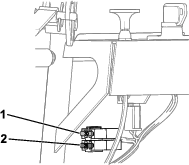
Open the bypass valves by turning them counterclockwise 1 to 2 turns (Figure 12).
Note: This allows hydraulic fluid to bypass the pumps and the wheels to turn.
-
Disengage the parking brake.
-
Push the machine to the desired location.
-
Engage the parking brake.
-
Close the bypass valves, but do not overtighten them.
Note: Rotate the bypass valves a maximum of 2 turns so that the valve does not come out of the body, causing fluid to run out.
Important: Do not start or operate the machine with the bypass valves open. Damage to the system may occur.
Transporting the Machine
Use a heavy-duty trailer or truck to transport the machine. Ensure that the trailer or truck has all necessary lighting and marking as required by law. Please carefully read all the safety instructions. Knowing this information could help you, your family, pets or bystanders avoid injury.
-
Secure a trailer to towing vehicle with safety chains.
-
Shut off the engine, remove the key, and wait for all moving parts to stop before leaving the operating position.
-
Securely fasten the machine to the trailer or truck with straps, chains, cable, or ropes.
Maintenance
Note: Determine the left and right sides of the machine from the normal operating position.
Maintenance Safety
-
Before adjusting, cleaning, servicing, or leaving the machine, do the following:
-
Park the machine on a level surface.
-
Move the throttle switch to the low-idle position.
-
Disengage the cutting units.
-
Ensure that the transmission is in neutral.
-
Engage the parking brake.
-
Shut off the engine and remove the key.
-
Wait for all moving parts to stop.
-
Allow machine components to cool before performing maintenance.
-
-
Do not allow untrained personnel to service the machine.
-
If the engine must be running to perform a maintenance adjustment, keep your hands, feet, clothing, and any parts of the body away from the cutting unit, attachments, and any moving parts. Keep bystanders away.
-
Keep all parts in good working condition. Replace all worn, damaged, or missing parts and decals. Keep all fasteners tight to ensure that the machine is in safe working condition.
-
Check the grass catcher components frequently and replace them when they are worn or damaged.
-
Clean grass and debris from the cutting unit, drives, muffler, cooling screen, and the engine to help prevent fires. Clean up oil or fuel spills.
-
Check the brake operation frequently. Adjust and service the brake as needed.
-
Carefully release pressure from components with stored energy.
-
To ensure safe, optimal performance of the machine, use only genuine Toro replacement parts. Replacement parts made by other manufacturers could be dangerous, and such use could void the product warranty.
Recommended Maintenance Schedule(s)
| Maintenance Service Interval | Maintenance Procedure |
|---|---|
| After the first 8 hours |
|
| Before each use or daily |
|
| Every 25 hours |
|
| Every 50 hours |
|
| Every 100 hours |
|
| Every 200 hours |
|
| Every 250 hours |
|
| Every 500 hours |
|
Important: Refer to the engine owner’s manual for additional maintenance procedures.
Caution
If you leave the key in the switch, someone could accidently start the engine and seriously injure you or bystanders.
Shut off the engine and remove the key from the switch before you perform any maintenance.
Lubrication
Greasing the Machine
Grease the machine more often in dirty or dusty conditions.
Grease Type: No. 2 lithium or molybdenum grease
-
Park the machine on a level surface, disengage the blade-control switch (PTO), and engage the parking brake.
-
Shut off the engine, remove the key, and wait for all moving parts to stop before leaving the operating position.
-
Clean the grease fittings with a rag.
Note: Scrape any paint off the front of the fitting(s).
-
Pump grease into the fittings until grease begins to ooze out of the bearings.
-
Wipe up any excess grease.
Engine Maintenance
Engine Safety
-
Do not change the governor speed or overspeed the engine.
-
Run the engine dry or remove the fuel with a hand pump; never siphon the fuel. If you must drain the fuel tank, do it outdoors.
Servicing the Air Cleaner
| Maintenance Service Interval | Maintenance Procedure |
|---|---|
| Every 25 hours |
|
| Every 50 hours |
|
| Every 200 hours |
|
Note: Service the air cleaner more frequently (every few operating hours) if the operating conditions are extremely dusty or sandy.
Important: Do not apply oil to the foam or paper element.
Removing the Foam and Paper Elements
-
Park the machine on a level surface, disengage the PTO, and engage the parking brake.
-
Shut off the engine, remove the key, and wait for all moving parts to stop before leaving the operating position.
-
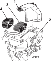
Clean the area around the air cleaner to prevent dirt from entering the engine and causing damage (Figure 14).
-
Unscrew the cover knobs and remove the air-cleaner cover (Figure 14).
-
Unscrew the hose clamp and remove the air-cleaner assembly (Figure 14).
-
Carefully pull the foam element off the paper element (Figure 14).
Cleaning the Foam Air-Cleaner Element
-
Wash the foam element in liquid soap and warm water. When the element is clean, rinse it thoroughly.
-
Dry the element by squeezing it in a clean cloth.
Important: Replace the foam element if it is torn or worn.
Servicing the Paper Air-Cleaner Element
Important: Do not clean the paper filter, replace it (Figure 14).
-
Inspect the element for tears, an oily film, or damage to the rubber seal.
-
Replace the paper element if it is damaged.
Installing the Foam and Paper Elements
Important: To prevent engine damage, always operate the engine with the complete foam and paper air-cleaner assembly installed.
Servicing the Engine Oil
Note: Change the oil more frequently when the operating conditions are extremely dusty or sandy.
Engine-Oil Specifications
Engine-Oil Type: Detergent oil (API service SF, SG, SH, SJ, or SL)
Crankcase Capacity: 1.7 L (58 oz) with the filter removed; 1.5 L (51 oz) without the filter removed
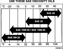
Viscosity: Refer to the table (Figure 15).
Checking the Engine-Oil Level
| Maintenance Service Interval | Maintenance Procedure |
|---|---|
| Before each use or daily |
|
Note: Check the oil when the engine is cold.
Important: If you overfill or underfill the engine crankcase with oil and run the engine, you may damage the engine.
-
Park the machine on a level surface, disengage the PTO, and engage the parking brake.
-
Shut off the engine, remove the key, and wait for all moving parts to stop before leaving the operating position.
Note: Ensure that the engine is cool so that the oil has had time to drain into the sump.
-
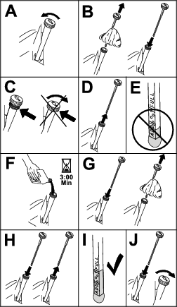
To keep dirt, grass clippings, etc., out of the engine, clean the area around the oil-fill cap and dipstick before removing it (Figure 16).
Changing the Engine Oil
| Maintenance Service Interval | Maintenance Procedure |
|---|---|
| After the first 8 hours |
|
| Every 100 hours |
|
-
Park the machine so that the drain side is slightly lower than the opposite side to ensure that the oil drains completely.
-
Disengage the PTO and engage the parking brake.
-
Shut off the engine, remove the key, and wait for all moving parts to stop before leaving the operating position.
-
Drain the oil from the engine (Figure 17).
-
Slowly pour approximately 80% of the specified oil into the filler tube and slowly add the additional oil to bring it to the Full mark (Figure 18).
-
Dispose of the used oil at a recycling center.
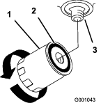
Changing the Engine-Oil Filter
| Maintenance Service Interval | Maintenance Procedure |
|---|---|
| Every 200 hours |
|
-
Drain the oil from the engine; refer to Changing the Engine Oil.
-
Change the engine-oil filter (Figure 19).
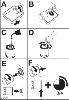
Note: Ensure that the oil-filter gasket touches the engine, and then turn the oil filter an extra 3/4 turn.
-
Fill the crankcase with the proper type of new oil (Figure 18).
Servicing the Spark Plug
| Maintenance Service Interval | Maintenance Procedure |
|---|---|
| Every 100 hours |
|
Ensure that the air gap between the center and side electrodes is correct before installing the spark plug. Use a spark plug wrench for removing and installing the spark plug and a gapping tool or feeler gauge to check and adjust the air gap. Install a new spark plug if necessary.
Type of Spark Plug: NGK® BPR4ES or equivalent
Air Gap: 0.75 mm (0.03 inch)
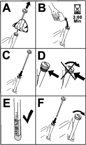
Removing the Spark Plug
-
Park the machine on a level surface, disengage the PTO, and engage the parking brake.
-
Shut off the engine, remove the key, and wait for all moving parts to stop before leaving the operating position.
-
Clean the area around the base of the plug to keep dirt and debris out of the engine.
-
Remove the spark plug (Figure 20).
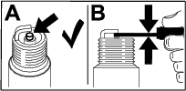
Checking the Spark Plug
Important: Do not clean the spark plug(s). Always replace the spark plug(s) when it has a black coating, worn electrodes, an oily film, or cracks.
If you see light brown or gray on the insulator, the engine is operating properly. A black coating on the insulator usually means the air cleaner is dirty.
Set the gap to 0.75 mm (0.03 inch).
Installing the Spark Plug
Fuel System Maintenance
Danger
In certain conditions, fuel is extremely flammable and highly explosive. A fire or explosion from fuel can burn you and others and can damage property.
Refer to Fuel Safety for a complete list of fuel related precautions.
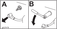
Draining the Fuel Tank
-
Park the machine on a level surface, disengage the PTO, and engage the parking brake.
-
Shut off the engine, remove the key, and wait for all moving parts to stop before leaving the operating position.
-
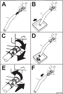
Close the fuel-shutoff valve at the fuel tank (Figure 23).
-
Squeeze the ends of the hose clamp together and slide it up the fuel line away from the fuel filter (Figure 23).
-
Pull the fuel line off the fuel filter (Figure 23).
-
Open the fuel-shutoff valve and allow the fuel to drain into a fuel container or drain pan.
Note: Replace the fuel filter, if needed; refer to Replacing the Fuel Filter.
-
Install the fuel line to the fuel filter. Slide the hose clamp close to the valve to secure the fuel line.
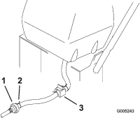
-
Wipe up any spilled fuel.
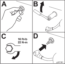
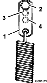
Replacing the Fuel Filter
| Maintenance Service Interval | Maintenance Procedure |
|---|---|
| Every 200 hours |
|
Important: Never install a dirty filter if it is removed from the fuel line.
-
Park the machine on a level surface, disengage the PTO, and engage the parking brake.
-
Shut off the engine, remove the key, and wait for all moving parts to stop before leaving the operating position.
-
Close the fuel-shutoff valve.
-
Replace the filter as shown in Figure 24.
Note: Ensure that the flow-direction arrow on the replacement filter points toward the engine.
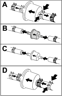
-
Open the fuel-shutoff valve.
-
Check for fuel leaks and repair, if needed.
-
Wipe up any spilled fuel.
Electrical System Maintenance
Electrical System Safety
-
Disconnect the battery before repairing the machine. Disconnect the negative terminal first and the positive last. Connect the positive terminal first and the negative last.
-
Charge the battery in an open, well-ventilated area, away from sparks and flames. Unplug the charger before connecting or disconnecting the battery. Wear protective clothing and use insulated tools.
Servicing the Battery
| Maintenance Service Interval | Maintenance Procedure |
|---|---|
| Every 100 hours |
|
Always keep the battery clean and fully charged. Use a paper towel to clean the battery case. If the battery terminals are corroded, clean them with a solution of four parts water and 1 part baking soda. Apply a light coating of grease to the battery terminals to prevent corrosion.
Voltage: 12 V
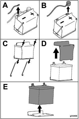
Removing the Battery
-
Park the machine on a level surface, disengage the PTO, and engage the parking brake.
-
Shut off the engine, remove the key, and wait for all moving parts to stop before leaving the operating position.
-
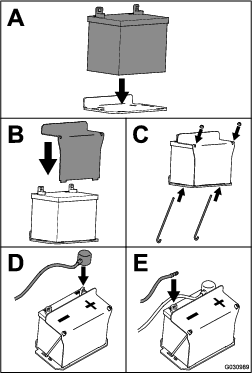
Remove the battery as shown in Figure 25.
Charging the Battery
Warning
Charging the battery produces gasses that can explode.
Never smoke near the battery and keep sparks and flames away from battery.
Important: Always keep the battery fully charged (1.265 specific gravity) to prevent battery damage when the temperature is below 0°C (32°F).
-
Remove the battery from the chassis; refer to Removing the Battery.
-
Check the electrolyte level.
-
Ensure that the filler caps are installed on the battery.
-
Charge the battery for 1 hour at 25 to 30 A or 6 hours at 4 to 6 A.
-
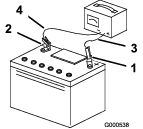
When the battery is fully charged, unplug the charger from the electrical outlet, and disconnect the charger leads from the battery posts (Figure 26).
-
Install the battery onto the machine and connect the battery cables; refer to Installing the Battery.
Note: Do not run the machine with the battery disconnected; electrical damage may occur.
Installing the Battery
Install the battery as shown in Figure 27.
Servicing the Fuses
The electrical system is protected by fuses. It requires no maintenance. If a fuse blows, check the component or circuit for a malfunction or short.
-
Park the machine on a level surface, disengage the PTO, and engage the parking brake.
-
Shut off the engine, remove the key, and wait for all moving parts to stop before leaving the operating position.
-
Pull out the fuse and replace it.
Drive System Maintenance
Perform the following linkage adjustments, Adjusting the Speed-Control Linkage through Adjusting the Tracking, when the machine needs maintenance. If any adjustment is needed, do them in the order that they are listed.
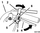
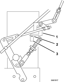
Adjusting the Speed-Control Linkage
-
Park the machine on a level surface, disengage the PTO, and engage the parking brake.
-
Shut off the engine, remove the key, and wait for all moving parts to stop before leaving the operating position.
-
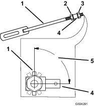
Move the speed-control lever to the fully FORWARD position.
-
Check the orientation of the tabs on the ends of the speed-control crank.
The tabs should point straight down at the 6 o'clock position (approximately) as shown in Figure 29.
-
Adjust the threaded yoke at the bottom of the speed-control linkage until the tabs are at the 6 o'clock position (Figure 29).
-
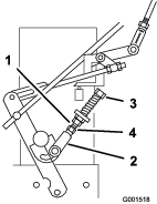
Move the speed-control lever to the NEUTRAL position.
-
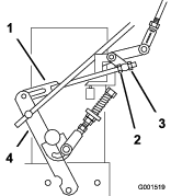
Ensure that the safety switch is pressed and there is a 8 mm (5/16 inch) space between the actuating tab and switch (Figure 30).
-
If needed, adjust the switch location to create the 8 mm (5/16 inch) space (Figure 30).
Adjusting the Neutral-Control Linkages
Warning
The engine must be running when you perform the control linkage adjustments. Contact with moving parts or hot surfaces may cause personal injury.
Keep your hands, feet, face, clothing and other body parts away from rotating parts, muffler and other hot surfaces.
Warning
Mechanical or hydraulic jacks may fail to support the machine and may cause serious injury.
-
Use jack stands when the supporting machine.
-
Do not use hydraulic jacks.
-
Park the machine on a level surface, disengage the PTO, and engage the parking brake.
-
Shut off the engine, remove the key, and wait for all moving parts to stop before leaving the operating position.
-
Raise the rear of the machine on to jack stands to raise the drive wheels off the ground.
-
Disengage the parking brake.
-
Start the engine and move the throttle to the FAST position.
-
Place the neutral locks in the full forward position and move the speed-control lever to the medium speed position.
-
Hold the OPC levers down.
Note: Hold the OPC levers down whenever the speed-control lever is out of the NEUTRAL position; otherwise, the engine shuts off.
Warning
The electrical system does not perform proper safety shut off with the operator-presence control (OPC) levers held down.
-
Ensure that the OPC levers are working when the adjustment is completed.
-
Never operate the machine with the OPC levers held down.
-
-
Squeeze 1 drive lever until you feel an increase in resistance.
This is where neutral should be.
Note: Ensure that you have not reached the end of the neutral-lock slot. If you have, shorten the control-lever linkage; refer to Adjusting the Control Rod.
-
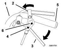
If the wheel turns while holding the drive lever in the NEUTRAL position, the neutral-control linkages need to be adjusted (Figure 31).
If the wheel stops, proceed to step 12.
-
Loosen the nut against the neutral-control linkage yoke (Figure 31).
-
Adjust the neutral-control linkage until the respective drive wheel stops while the drive lever is pulled against the neutral spring (NEUTRAL position) as shown in Figure 31.
-
Turn the adjusting bolt approximately 1/4 turn clockwise if the wheel is turning in reverse. Turn the bolt approximately 1/4 turn counterclockwise if the wheel is turning forward (Figure 31).
-
Release the drive lever to the FORWARD drive position and squeeze back into the NEUTRAL position.
-
Check if the wheel stops. If not, repeat the adjustment procedure.
-
After the adjustments are made, tighten the nuts against the yokes.
-
Repeat this procedure for the opposite side.
Adjusting the Hydraulic Control Linkages
Warning
The engine must be running when you perform the control linkage adjustments. Contact with moving parts or hot surfaces may cause personal injury.
Keep your hands, feet, face, clothing and other body parts away from rotating parts, muffler and other hot surfaces.
Warning
Mechanical or hydraulic jacks may fail to support the machine and may cause serious injury.
-
Use jack stands when the supporting machine.
-
Do not use hydraulic jacks.
Adjusting the Left Linkage
-
Park the machine on a level surface, disengage the PTO, and engage the parking brake.
-
Shut off the engine, remove the key, and wait for all moving parts to stop before leaving the operating position.
-
Raise the rear of the machine on to jack stands to raise the drive wheels off the ground.
-
Disengage the parking brake.
-
Start the engine and move the throttle to the FAST position.
-
Move the left drive lever to the full forward position.
-
Move the speed-control lever to the NEUTRAL position.
Warning
The electrical system does not perform proper safety shut off with the operator-presence control (OPC) levers held down.
-
Ensure that the OPC levers are working when the adjustment is completed.
-
Never operate the machine with the OPC levers held down.
-
-
Loosen the front adjusting nut on left hydraulic control linkage (Figure 33).
-
Turn the left, rear adjusting nut counterclockwise until the wheel rotates forward (Figure 33).
-
Turn the rear adjusting nut clockwise 1/4 of a turn at a time. Then, move the speed-control lever to the FORWARD position and back to the NEUTRAL position. Repeat this until the left wheel stops rotating forward (Figure 33).
-
Turn the rear nut an additional 1/2 turn and tighten the front adjusting nut.
Note: Ensure that the flat part of the linkage is perpendicular to the pin part of the swivel.
-
After adjusting the left hydro-control linkage, move the speed-control lever to the FORWARD position and then back to the NEUTRAL position.
-
Hold the OPC levers down.
Note: Hold the OPC levers down whenever the speed-control lever is out of the NEUTRAL position; otherwise, the engine shuts off.
-
Ensure that the speed-control lever is in the NEUTRAL position and that the tire does not rotate.
-
Repeat the adjustment, if needed.
Note: If inconsistent neutral occurs, check to ensure that both springs are properly tightened on the speed-control lever under the console, especially the rear pivot spring. Repeat the above adjustments, if necessary (Figure 34).
Adjusting the Right Linkage
-
Move the speed-control lever to the NEUTRAL position.
-
Move the right drive lever to the full FORWARD position.
-
Adjust the right linkage by turning the quick track knob counterclockwise until the tire begins to rotate forward (Figure 35).
-
Turn the knob clockwise 1/4 of a turn at a time. Then, move the speed-control lever to the FORWARD position and back to the NEUTRAL position. Repeat this until the right wheel stops rotating forward (Figure 35).
-
Hold the OPC levers down.
Note: Hold the OPC levers down whenever the speed-control lever is out of the NEUTRAL position; otherwise, the engine shuts off.
-
The spring that keeps tension on the knob should normally not need adjustment; however, if an adjustment is needed, adjust the length of the spring to 26 mm (1 inch) between the washers (Figure 35).
-
Adjust the spring length by turning the nut at the front of the spring (Figure 35).

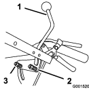
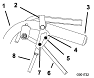
Adjusting the Control Rod
Checking the Control Rod
-
With the rear of the machine still on jack stands and the engine running at full throttle, move the speed-control lever to the MEDIUM speed position.
Note: Hold the OPC levers down whenever the speed-control lever is out of the NEUTRAL position; otherwise, the engine shuts off.
-
Move the respective drive lever upward until it reaches the NEUTRAL position and engage the neutral locks.
-
If the tire rotates in either direction, you need to adjust the length of the control rod.
Adjusting the Control Rod
-
Adjust the rod length by releasing the drive lever and removing the hairpin cotter and clevis pin (Figure 36). Rotate the rod in the rod fitting (Figure 36).
-
Lengthen the control rod if the tire is turning in reverse or shorten the rod if the tire is turning forward.
-
Rotate the rod several turns if the tire is rotating quickly. Then, adjust the rod in 1/2-turn increments.
-
Install the clevis pin into the drive lever (Figure 36).
-
Release and engage the neutral lock, and ensure that the tire does not rotate (Figure 37).
Continue this process until the tire does not rotate.
-
Install the hairpin cotter between the drive levers and neutral locks and into the clevis pins (Figure 36).
-
Repeat this adjustment on the other side of the machine.
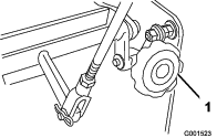
Adjusting the Tracking
If the machine does not track straight, adjustment is required.
-
Remove the machine from the jack stands.
-
Check the rear tire pressure; refer to Checking the Tire Pressure.
-
Run the machine and observe the tracking on a level, smooth, hard surface, such as concrete or asphalt.
-
If the machine tracks to either side, turn the quick-track knob. Turn the knob right to steer right and turn the knob left to steer left (Figure 38).
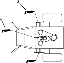
Adjusting the Spring-Anchor Links
For medium-duty or heavy-duty drive conditions, such as operating with a sulky on steep slopes, a higher spring force may be required on the hydro-pump control arms to prevent the drive system from stalling.
-
Park the machine on a level surface, disengage the PTO, and engage the parking brake.
-
Shut off the engine, remove the key, and wait for all moving parts to stop before leaving the operating position.
-
For a heavier drive setting, relocate the spring-anchor links to either the medium-duty or heavy-duty positions (Figure 39).
Note: The spring-anchor links are attached to the upper, rear corner of the hydro-drive shields on the left and right sides of the machine.
Note: In the medium-duty or heavy-duty positions, the drive lever forces at the upper handle will also be increased.
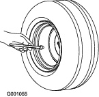
Checking the Tire Pressure
| Maintenance Service Interval | Maintenance Procedure |
|---|---|
| Every 50 hours |
|
Maintain the air pressure in the rear tires as specified. Check the pressure at the valve stem (Figure 40).
Rear Tire Pressure: 103 kPa (15 psi)
Cooling System Maintenance
Cleaning the Air-Intake Screen
| Maintenance Service Interval | Maintenance Procedure |
|---|---|
| Before each use or daily |
|
Remove any buildup of grass, dirt, or other debris from the cylinder and cylinder head cooling fins, the air-intake screen on the flywheel end, and the carburetor-governor levers and linkage. This helps ensure adequate cooling and correct engine speed to reduce the possibility of overheating or mechanical damage to the engine.
Brake Maintenance
Servicing the Parking Brake
Checking the Parking Brake
| Maintenance Service Interval | Maintenance Procedure |
|---|---|
| Before each use or daily |
|
Check the brakes on both a level surface and a slope.
-
Park the machine on a level surface and disengage the PTO.
-
Shut off the engine, remove the key, and wait for all moving parts to stop before leaving the operating position.
-
Engage the parking brake.
Note: Engaging the parking brake should take a reasonable amount of force. If the parking brake does not hold securely, adjust it; refer to Adjusting the Parking Brake.
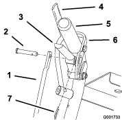
Adjusting the Parking Brake
If the parking brake does not hold securely, adjust it.
-
Check the parking brake before you adjust it; refer to Checking the Parking Brake.
-
Disengage the parking brake.
-
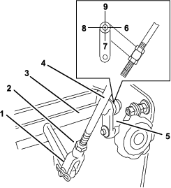
Remove the hairpin cotter from the lower brake link (Figure 41).
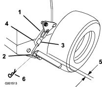
-
Rotate the lower brake linkage yoke clockwise into the yoke to tighten the parking brake; rotate the brake linkage yoke counterclockwise out of the yoke out to loosen the parking brake (Figure 41).
Note: With the parking brake in the disengaged position, the clearance between the tire and the flat bar is approximately 6 mm (1/4 inch).
-
Secure the lower link to the lower brake lever using the hairpin cotter and the clevis pin (Figure 41).
-
Check the brake operation again; refer to Checking the Parking Brake.
Belt Maintenance
Inspecting the Belts
| Maintenance Service Interval | Maintenance Procedure |
|---|---|
| Every 25 hours |
|
Replace the belt if it is worn. The signs of a worn belt include squealing while the belt is rotating; the blades slipping while cutting grass; and frayed edges, burn marks, and cracks on the belt.
Hydraulic System Maintenance
Hydraulic System Safety
-
Seek immediate medical attention if fluid is injected into skin. Injected fluid must be surgically removed within a few hours by a doctor.
-
Ensure that all hydraulic-fluid hoses and lines are in good condition and all hydraulic connections and fittings are tight before applying pressure to the hydraulic system.
-
Keep your body and hands away from pinhole leaks or nozzles that eject high-pressure hydraulic fluid.
-
Use cardboard or paper to find hydraulic leaks.
-
Safely relieve all pressure in the hydraulic system before performing any work on the hydraulic system.
Hydraulic-Fluid Specifications
Hydraulic-Fluid Type: Toro® HYPR-OIL™ 500 hydraulic fluid or Mobil® 1 15W-50
Hydraulic-Fluid Capacity: 2.3 L (2.4 US qt)
Important: Use the specified fluid only. Other fluids could cause system damage.
Checking the Hydraulic-Fluid Level
| Maintenance Service Interval | Maintenance Procedure |
|---|---|
| After the first 8 hours |
|
| Every 25 hours |
|
Note: You can check the oil when the fluid is warm or cold. The baffle inside the tank has 2 levels depending on the temperature.
-
Park the machine on a level surface, disengage the PTO, and engage the parking brake.
-
Shut off the engine, remove the key, and wait for all moving parts to stop before leaving the operating position.
-
Clean the area around the cap and filler neck of the hydraulic tank (Figure 42).

-
Remove the cap from the filler neck. Look inside to check if there is fluid in the reservoir (Figure 42).
-
If there is no fluid, add fluid to the reservoir until it reaches the cold level of the baffle.
-
Run the machine at low idle for 15 minutes to allow any air to purge out of the system and warm the fluid.
-
Check the fluid level while the fluid is warm. If required, add fluid to the reservoir until it reaches the hot level of the baffle.
Note: The fluid level should be to the top of the hot level of the baffle when the fluid is warm (Figure 42).
-
Install the cap on the filler neck.
Replacing the Hydraulic Fluid and Filter
| Maintenance Service Interval | Maintenance Procedure |
|---|---|
| After the first 8 hours |
|
| Every 250 hours |
|
| Every 500 hours |
|
Important: Do not substitute an automotive oil filter; otherwise, severe hydraulic system damage may result.
-
Park the machine on a level surface, disengage the PTO, and engage the parking brake.
-
Shut off the engine, remove the key, and wait for all moving parts to stop before leaving the operating position.
-
Remove the hydraulic-reservoir cap and temporarily cover the opening with a plastic bag and a rubber band to prevent all of the hydraulic fluid from draining out.
-
Locate the hydraulic filter under the engine base and place a drain pan under the filter (Figure 43).
-
Remove the old filter and wipe the filter-adapter gasket surface clean (Figure 43).
-
Apply a thin coat of hydraulic fluid to the rubber gasket on the new filter.
-
Install replacement hydraulic filter onto the filter adapter. Do not tighten.
-
Remove the plastic bag from the reservoir opening and allow the filter to fill with hydraulic fluid.
-
When the hydraulic filter is full, turn the hydraulic filter clockwise until the rubber gasket contacts the filter adapter; then, tighten the filter an additional 1/2 turn (Figure 43).
-
Clean up any spilled fluid.
-
If there is no fluid, add fluid to approximately 6 mm (1/4 inch) below the top of the reservoir baffle; refer to Hydraulic-Fluid Specifications.
-
Start the engine and let it run for about 2 minutes to purge any air from the system. Shut off the engine and check for leaks. If 1 or both wheels do not drive, refer to Bleeding the Hydraulic System.
-
Check the level and add fluid, if required. Do not overfill.
Bleeding the Hydraulic System
The traction system is self-bleeding; however, it may be necessary to bleed the system if you change the fluid or after work is performed on the system.
Purge the air from the hydraulic system when any hydraulic components, including the hydraulic filter, are removed or any of the hydraulic lines are disconnected. The critical area for purging air from the hydraulic system is between the fluid reservoir and each charge pump located on the top of each variable-displacement pump. Air in other parts of the hydraulic system purge through normal operation once the charge pump is primed.
-
Park the machine on a level surface, disengage the PTO, and engage the parking brake.
-
Shut off the engine, remove the key, and wait for all moving parts to stop before leaving the operating position.
-
Raise the rear of the machine up with jack stands high enough to raise the drive wheels off the ground.
-
Check the hydraulic-fluid level.
-
Start the engine and move the throttle control to the FAST position. Move the speed-control lever midway between the FAST and SLOW positions and place the drive levers into the DRIVE position.
Note: If either drive wheel does not rotate, it is possible to assist the purging of the charge pump by carefully rotating the tire in the forward direction.
Important: It is necessary to lightly touch the charge-pump cap with your hand to check the pump temperature. If the cap is too hot to touch, shut off the engine. The pumps may be damaged if the pump becomes too hot. If either drive wheel still does not rotate, continue to the next step.
-
Thoroughly clean the area around each of the charge-pump housings.
-
Prime the charge pump as follows:
-
Shut off the engine and remove the key.
-
Loosen the 2 socket-head capscrews (Figure 44) 1-1/2 turns only.
-
Lift the charge pump housing upward and wait for a steady flow of fluid to flow out from under the housing.
-
Tighten the capscrews.
-
Repeat this for both pumps.
Note: The hydraulic reservoir can be pressurized to up to 34.5 kPa (5 psi) to speed up this process.
-
-
If either drive wheel still does not rotate, stop and repeat steps 4 and 5 on the respective pump. If the wheels rotate slowly, the system may prime after additional running.
-
Check the hydraulic-fluid level.
-
Allow the machine to run for several minutes after the charge pumps are primed with the drive system in the FAST position.
-
Check the hydraulic-control linkage adjustment; refer to Adjusting the Hydraulic Control Linkages.
Checking the Hydraulic Hoses
| Maintenance Service Interval | Maintenance Procedure |
|---|---|
| Every 100 hours |
|
Check the hydraulic hoses for leaks, loose fittings, kinked lines, loose mounting supports, wear, and weather and chemical deterioration. Make necessary repairs before operating.
Note: Keep the areas around the hydraulic system clean from grass and debris buildup.
Cleaning
Cleaning under the Mower
| Maintenance Service Interval | Maintenance Procedure |
|---|---|
| Before each use or daily |
|
Remove the grass buildup under the mower daily.
-
Park the machine on a level surface, disengage the PTO, and engage the parking brake.
-
Shut off the engine, remove the key, and disconnect the spark-plug wires from the spark plugs.
-
Raise the front of the machine using a jack and use jack stands to support the machine.
-
Clean the machine with a rag. Do not spray the machine.
Disposing of Waste
Engine oil, batteries, hydraulic fluid, and engine coolant are pollutants to the environment. Dispose of these according to your state and local regulations.
Storage
Storage Safety
-
Always shut off the machine, remove the ignition key, wait for all moving parts to stop, and allow the machine to cool before adjusting, servicing, cleaning, or storing it.
-
Let the engine cool before storing the machine.
-
Do not store the machine or fuel near flames or drain the fuel indoors.
Cleaning and Storing the Machine
-
Park the machine on a level surface, disengage the PTO, and engage the parking brake.
-
Shut off the engine, remove the key, and wait for all moving parts to stop before leaving the operating position.
-
Remove grass clippings, dirt, and grime from the external parts of the entire machine, especially the engine and hydraulic system.
Important: You can wash the machine with mild detergent and water. Do not pressure-wash the machine. Avoid excessive use of water, especially near the control panel, engine, hydraulic pumps, and motors.
-
Check the parking brake operation; refer to Checking the Parking Brake.
-
Service the air cleaner; refer to Servicing the Air Cleaner.
-
Grease the machine; refer to Greasing the Machine.
-
Change the crankcase oil; refer to Changing the Engine Oil.
-
Check the tire pressure; refer to Checking the Tire Pressure.
-
Charge the battery; refer to Charging the Battery.
-
Scrape any heavy buildup of grass and dirt from the underside of the mower, then wash the machine with a garden hose.
Note: Run the machine with the blade-control switch (PTO) engaged and the engine at high idle for 2 to 5 minutes after washing.
-
Check the condition of the blades; refer to the Operator’s Manual for the mower deck.
-
Prepare the machine for storage for over 30 days as follows:
-
Add fuel stabilizer/conditioner to fresh fuel in the tank. Follow mixing instructions from the fuel stabilizer manufacturer. Do not use an alcohol-based stabilizer (ethanol or methanol).
-
Run the engine to distribute conditioned fuel through the fuel system for 5 minutes.
-
Shut off the engine, allow it to cool, and drain the fuel tank.
-
Start the engine and run it until it shuts off.
-
Dispose of fuel properly. Recycle the fuel according to local codes.
Important: Do not store fuel containing stabilizer/conditioner longer than the duration recommended by the fuel-stabilizer manufacturer.
-
-
Remove and check the condition of the spark plug(s); refer to Servicing the Spark Plug. With the spark plug(s) removed from the engine, pour 30 ml (2 tablespoons) of engine oil into the spark plug hole. Use the starter to crank the engine and distribute the oil inside the cylinder. Install the spark plug(s). Do not install the wire on the spark plug(s).
-
Check and tighten all fasteners. Repair or replace any part that is damaged.
-
Paint all scratched or bare metal surfaces. Paint is available from your Authorized Service Dealer.
-
Store the machine in a clean, dry garage or storage area. Remove the key from the switch and keep it out of reach of children or other unauthorized users. Cover the machine to protect it and keep it clean.
Troubleshooting
| Problem | Possible Cause | Corrective Action |
|---|---|---|
| The engine does not start, starts hard, or fails to keep running. |
|
|
| The engine loses power. |
|
|
| The engine overheats. |
|
|
| The machine does not drive. |
|
|
| The machine is vibrating abnormally. |
|
|
| The cutting height is uneven. |
|
|
| The blades do not rotate. |
|
|
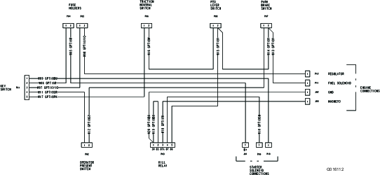
Schematics
Electrical Schematic
Hydraulic Schematic