
 , which means
Caution, Warning, or Danger—personal safety instruction. Failure
to comply with these instructions may result in personal injury or
death.
, which means
Caution, Warning, or Danger—personal safety instruction. Failure
to comply with these instructions may result in personal injury or
death.

Maintenance
Recommended Maintenance Schedule(s)
| Maintenance Service Interval | Maintenance Procedure |
|---|---|
| Before each use or daily |
|
| Every 50 hours |
|
Caution
If you leave the key in the switch, someone could accidently start the engine and seriously injure you or other bystanders.
Remove the key from the switch before you perform any maintenance.
Maintenance Safety
-
Before adjusting, cleaning, servicing, or leaving the machine, do the following:
-
Position the machine on a level surface.
-
Move the throttle switch to the low-idle position.
-
Disengage the PTO (if applicable).
-
Ensure that the traction is in neutral.
-
Engage the parking brake.
-
Shut off the engine of the traction unit and remove the key.
-
Wait for all moving parts to stop.
-
Allow machine components to cool before performing maintenance.
-
-
Perform only those maintenance instructions described in this manual. If major repairs are ever needed or assistance is desired, contact an authorized Bullseye distributor.
-
Ensure that the machine is in safe operating condition by keeping nuts, bolts, and screws tight.
-
If possible, do not perform maintenance while the engine is running. Keep away from moving parts.
-
Carefully release pressure from components with stored energy.
-
Support the machine with blocks or storage stands when working beneath it. Never rely on the hydraulic system to support the machine.
-
Never crawl under the attachment. If necessary, tilt the attachment.
-
Ensure that all guards are installed and secured after maintaining or adjusting the machine.
-
To ensure safe, optimal performance of the machine, use only genuine Bullseye replacement parts. Replacement parts made by other manufacturers could be dangerous, and such use could void the product warranty.
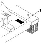
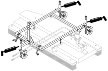
Removing the Frame and Cover
-
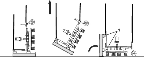
Remove the attachment from the traction unit; refer to Removing the Attachment.
-
Place blocks under the brush deck to support it.
Important: Do not place blocks under the brushes.
-
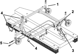
Remove the fasteners securing the 4 chains to the frame.
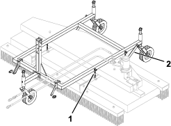
-
Remove the fasteners securing the 2 connecting rods to the frame.
-
Move the frame away from the deck.
-
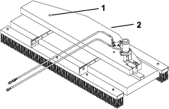
Remove the 2 nuts securing the cover and remove the cover.
Reverse the procedure to install the cover and frame.
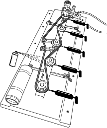
Greasing the Attachment
| Maintenance Service Interval | Maintenance Procedure |
|---|---|
| Every 50 hours |
|
The attachment has grease fittings that you must lubricate regularly with No. 2 lithium grease. Also, lubricate the attachment immediately after every washing and after long periods without use.
Note: Bearings without a grease fitting are maintenance-free.
-
Park the machine on a level surface.
-
Engage the parking brake, shut off the engine, and remove the key from the traction unit.
-
If you are lubricating the chain, remove the frame and cover; refer to Removing the Frame and Cover.
-
Grease the machine at the following locations:
-
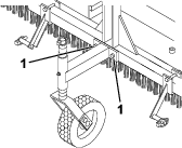
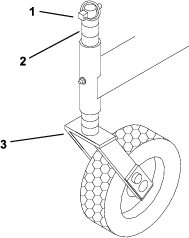
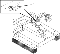
Caster wheel bearing (3)
-
Sprocket bearings (5)
-
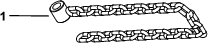
Chain (use chain lubricant)
-
-
Wipe up any excess grease.
-
Install the cover and frame, if removed.
Tensioning the Chain
| Maintenance Service Interval | Maintenance Procedure |
|---|
Important: If the chain breaks or is removed for service, manually calibrate the timing of the brush positions; otherwise, the brushes may interfere with each other during operation and damage the attachment. Refer to the Service Manual for information.
-
Park the machine on a level surface.
-
Engage the parking brake, shut off the engine, and remove the key from the traction unit.
-
Remove the frame and cover; refer to Removing the Frame and Cover.
-
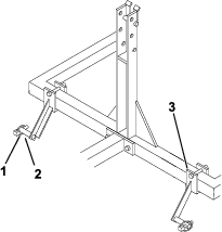
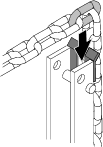
Loosen the set screw.
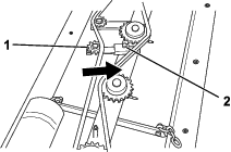
-
Push the chain tensioner in the direction of the arrow until the chain is tightly tensioned.
-
Tighten the set screw.
-
Install the cover.
Checking the Hydraulic Lines
| Maintenance Service Interval | Maintenance Procedure |
|---|---|
| Before each use or daily |
|
Warning
Hydraulic fluid escaping under pressure can penetrate skin and cause injury. Fluid injected into the skin must be surgically removed within a few hours by a doctor familiar with this form of injury; otherwise, gangrene may result.
-
Keep your body and hands away from pinhole leaks or nozzles that eject high-pressure hydraulic fluid.
-
Use cardboard or paper to find hydraulic leaks; never use your hands.