| Maintenance Service Interval | Maintenance Procedure |
|---|---|
| Before each use or daily |
|
Introduction
This machine is a multi-purpose machine intended to be used by professional, hired operators in commercial applications. It is designed primarily for mowing grass on well-maintained lawns in parks, golf courses, sports fields, along roadways, and on commercial grounds. Using this product for purposes other than its intended use could prove dangerous to you and bystanders.
Read this information carefully to learn how to operate and maintain your product properly and to avoid injury and product damage. You are responsible for operating the product properly and safely.
Visit www.Toro.com for product safety and operation training materials, accessory information, help finding a dealer, or to register your product.
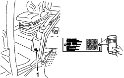
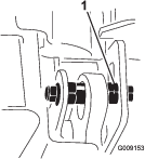
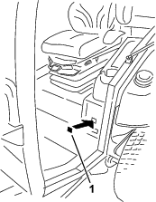
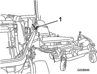
Whenever you need service, genuine Toro parts, or additional information, contact an Authorized Service Dealer or Toro Customer Service and have the model and serial numbers of your product ready. Figure 1 identifies the location of the model and serial numbers on the product. Write the numbers in the space provided.
Important: With your mobile device, you can scan the QR code on the serial number decal (if equipped) to access warranty, parts, and other product information.
This manual identifies potential hazards and has safety messages identified by the safety-alert symbol (Figure 2), which signals a hazard that may cause serious injury or death if you do not follow the recommended precautions.

This manual uses 2 words to highlight information. Important calls attention to special mechanical information and Note emphasizes general information worthy of special attention.
This product complies with all relevant European directives; for details, please see the separate product specific Declaration of Conformity (DOC) sheet.
It is a violation of California Public Resource Code Section 4442 or 4443 to use or operate the engine on any forest-covered, brush-covered, or grass-covered land unless the engine is equipped with a spark arrester, as defined in Section 4442, maintained in effective working order or the engine is constructed, equipped, and maintained for the prevention of fire.
The enclosed engine owner's manual is supplied for information regarding the US Environmental Protection Agency (EPA) and the California Emission Control Regulation of emission systems, maintenance, and warranty. Replacements may be ordered through the engine manufacturer.
Warning
CALIFORNIA
Proposition 65 Warning
Diesel engine exhaust and some of its constituents are known to the State of California to cause cancer, birth defects, and other reproductive harm.
Battery posts, terminals, and related accessories contain lead and lead compounds, chemicals known to the State of California to cause cancer and reproductive harm. Wash hands after handling.
Use of this product may cause exposure to chemicals known to the State of California to cause cancer, birth defects, or other reproductive harm.
Safety
This machine has been designed in accordance with ANSI B71.4-2017 and with EN ISO 5395 when you complete the setup procedures and install the CE kit, per the Declaration of Conformity.
General Safety
This product is capable of amputating hands and feet and of throwing objects. Always follow all safety instructions to avoid serious personal injury.
-
Read and understand the contents of this Operator’s Manual before starting the engine.
-
Use your full attention while operating the machine. Do not engage in any activity that causes distractions; otherwise, injury or property damage may occur.
-
Do not operate the machine without all guards and other safety protective devices in place and functioning properly on the machine.
-
Keep your hands and feet away from rotating parts. Keep clear of the discharge opening.
-
Keep bystanders and children out of the operating area. Never allow children to operate the machine.
-
Shut off the engine, remove the key, and wait for all movement to stop before you leave the operator’s position. Allow the machine to cool before adjusting, servicing, cleaning, or storing it.
Improperly using or maintaining this machine can result in injury.
To reduce the potential for injury, comply with these safety instructions
and always pay attention to the safety-alert symbol  , which means Caution, Warning,
or Danger—personal safety instruction. Failure to comply with
these instructions may result in personal injury or death.
, which means Caution, Warning,
or Danger—personal safety instruction. Failure to comply with
these instructions may result in personal injury or death.
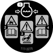
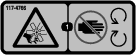
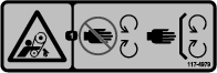
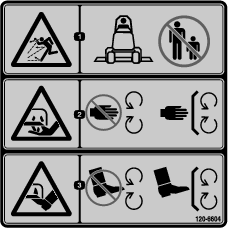
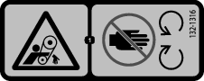
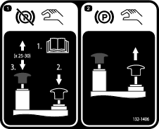
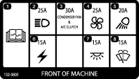
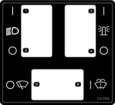
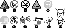
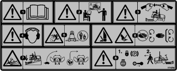
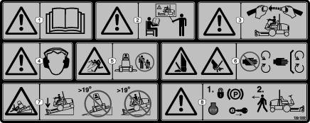
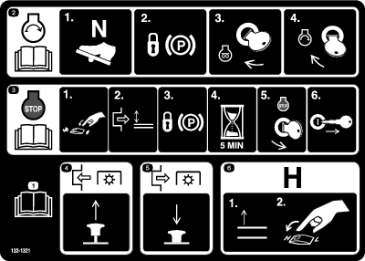
Safety and Instructional Decals
 |
Safety decals and instructions are easily visible to the operator and are located near any area of potential danger. Replace any decal that is damaged or missing. |


Setup
Note: Determine the left and right sides of the machine from the normal operating position.
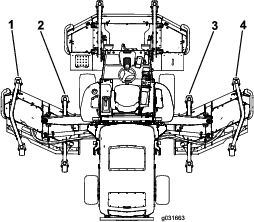
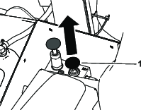
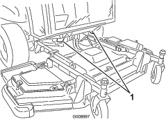
Removing the Wing-Deck-Shipping Straps and Braces
-
Park the machine on a level surface, engage the parking brake, shut off the engine, and remove the key.
-
Remove the straps and braces securing the wing decks for shipping.
Lowering the Front-Deck Winglets
Parts needed for this procedure:
| Right deck cover | 1 |
| Left deck cover | 1 |
| V-belt | 2 |
-
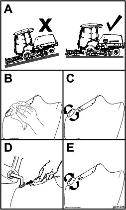
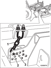
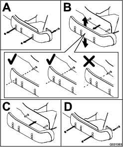
Remove the nuts securing the front and rear stop bolts to the right winglet-deck mounts (Figure 3).
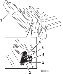
-
While supporting the right winglet, remove the front and rear stop bolts from the deck mounts (Figure 3).
Note: Leave the eccentrics positioned between the deck mounts.
-
Lower the winglet to the operating position.
-
Install the front and rear stop bolts through the upper-mounting holes and eccentrics (Figure 4).
Note: Ensure that the stop bolt engages the tab on the hinge pin.
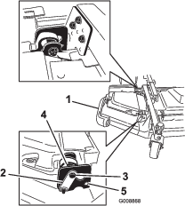
-
Install the nuts securing the stop bolts.
Note: Do not tighten the nuts at this time.
-
Repeat this procedure on the left winglet.
-
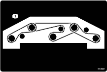
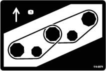
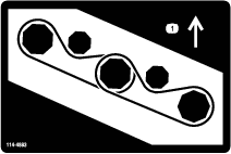
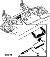
Install the winglet belts as follows:
-
Start the belt around the winglet-spindle pulley and the front-deck-spindle pulley (Figure 5).
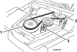
-
Using a ratchet wrench or a similar tool, move the idler pulley away from the pulleys (Figure 5).
-
Route the belt around the winglet-spindle pulley and the upper-spindle pulley on the front deck.
-
Release the idler pulley to put tension on the belt.
-
-
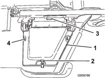
Install the winglet-deck cover and secure it with the rubber latch (Figure 6).
Note: Ensure that you slide the cover under the front, center deck-cover tabs before inserting it onto the mounting hooks and post.
-
Repeat this procedure on the other winglet.
Checking the Tire and Caster Wheel Pressure
Check the tire and caster wheel pressure before use; refer to Checking the Tire Pressure and Checking the Caster Wheel Tire Pressure.
Important: Maintain pressure in all tires to ensure a good quality-of-cut and proper machine performance. Do not underinflate the tires.
Important: Traction performance, including tire-slip control, is dependent on the ratio of the tire size between the front and rear tires. Use only genuine Toro tires.
Leveling the Front, Center Cutting Unit
Note: Perform this procedure on a flat, level surface.
Refer to Adjusting the Height of Cut.
-
Rotate the blade on each outer spindle until the ends face forward and backward.
-
Measure from the floor to the front tip of the blade.
-
Adjust the 3 mm (1/8 inch) shims on the front caster fork(s) to match the desired height of cut.
-
Rotate the blades 180° and measure from the floor to the rear-facing tip of the blade.
-
Loosen the lower jam nuts on the height-of-cut chain U-bolt.
-
Adjust the nuts to raise or lower the rear of the cutting unit so that the tips of the rear blades are 6 to 10 mm (1/4 to 3/8 inch) higher than the front tips.
-
Tighten the jam nuts.
Leveling the Winglet Decks to the Front, Center Cutting Unit
-
Rotate the blade on each winglet so that it points side to side.
-
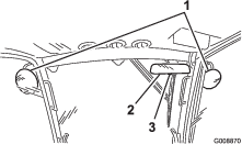
Loosen the bolts and nuts securing the 2 eccentric spacers to the winglets (Figure 7).
-
Rotate the forward eccentric until it reaches maximum clearance with the inner-slot surface of the winglet-pivot bracket.
-
Rotate the rear (closest to the traction unit) eccentric until the outside blade tip is about 3 mm (1/8 inch) higher than the desired height of cut (Figure 7).
Note: There is a notch on the eccentric hex, which is 180° from the lobe on the eccentric cam (Figure 8). Use the notches to reference the location of the lobes when adjusting the eccentrics.
-
Tighten the bolt and nut for this eccentric to 149 N·m (110 ft-lb).
-
Adjust the forward eccentric until it just makes contact with the inner slot surface of the winglet-pivot brackets.
-
Tighten the bolt and nut for this eccentric to 149 N·m (110 ft-lb).
-
Repeat the procedure on the opposite winglet.
Checking the Fluid Levels
-
Check the engine-oil level before starting the engine; refer to Checking the Engine-Oil Level.
-
Check the hydraulic-fluid level before starting the engine; refer to Checking the Hydraulic Fluid.
-
Check the cooling system before starting the engine; refer to Checking the Engine-Cooling System.
Greasing the Machine
Grease the machine before use; refer to Lubrication.
Important: Failure to properly grease the machine will result in premature failure of critical parts.
Installing the Decal (CE Machines Only)
Parts needed for this procedure:
| Production-year decal | 1 |
On machines requiring CE compliance, install the production-year decal included in the loose parts and the CE Kit, sold separately (Figure 9).
Product Overview
Note: Determine the left and right sides of the machine from the normal operating position.
Traction Pedal
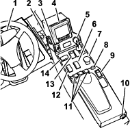
The traction pedal controls the forward and reverse operation. Press the top of the pedal to move the machine forward and the bottom to move it backward. Ground speed depends on how far you press the pedal. For maximum ground speed, fully press the pedal while the throttle is in the HIGH IDLE position (Figure 11).
To stop the machine, reduce your foot pressure on the traction pedal and allow it to return to the center position.
Parking-Brake Switch
The parking-brake switch requires 2 actions to engage the brake. While holding the small latch back, press the parking-brake switch forward to engage the parking brake. Press the parking-brake switch rearward to disengage the parking brake (Figure 11).
Hazard-Light Switch
Press the hazard-light switch forward to engage the hazard lights and rearward to disengage the hazard lights (Figure 11).
Turn-Signal Switch
Press the left side of the turn-signal switch to activate the left-turn signal and the right side of the switch to activate the right-turn signal (Figure 11).
Note: The center position is off.
Key Switch
The key switch has 3 positions: STOP, RUN/PREHEAT, and START (Figure 11).
PTO Switch
The PTO switch has 2 positions: OUT (start) and IN (stop). Pull out the PTO button to engage the implement or mower-deck blades. Push in the button to disengage the implement operation (Figure 11).
High-Low Range-Speed Switch
Press the front of the switch to select HIGH-SPEED RANGE. Press the rear of the switch to select LOW-SPEED RANGE. The machine must be stationary or traveling at less than 1.0 km/h (0.6 mph) to shift between HIGH and LOW (Figure 11).
Cruise-Control Switch
The cruise-control switch sets your desired speed of the machine.
Move the cruise-control switch to the center position to turn the cruise control to the ON position. Press the switch forward to set the speed. Press the switch rearward to disengage the cruise control (Figure 11).
Note: Foot pedal movement also disengages the cruise control.
When you engage the cruise control, you can change the cruise-control speed using the InfoCenter control.
Deck-Lift Switches
The deck-lift switches raise and lower the cutting units (Figure 11).
Press the switches forward to lower the cutting unit and rearward to raise the cutting unit.
Note: The cutting units do not lower while the machine is in the HIGH-speed range, and the cutting units do not raise or lower if you are out of the seat while the engine is running.
Note: The deck-raising function is limited at engine speeds below 2,000 rpm. Only 1 deck raises at a time below 2,000 rpm.
Throttle Switch
The throttle switch has 2 positions: LOW IDLE and HIGH IDLE (Figure 11).
Press the switch forward for 2 or more seconds to set the throttle at HIGH IDLE; press the switch rearward for 2 or more seconds to set the throttle at LOW IDLE; or momentarily press the switch in either direction to increase or decrease the engine speed in 100-rpm increments.
Light Switch
Press the light switch upward to turn the lights to the ON position (Figure 11).
Press the light switch downward to turn the lights to the OFF position.
Horn Button
Press the horn button to activate the horn (Figure 11).
Seat Adjustments
Seat-Adjustment Lever
Move the seat-adjustment lever on the side of the seat outward, slide the seat to the desired position, and release the lever to lock the seat into position (Figure 12).
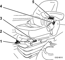
Armrest-Adjustment Knob
Rotate the knob to adjust the armrest angle (Figure 12).
Seat-Back-Adjustment Lever
Move the lever to adjust the seat-back angle (Figure 12).
Weight Gauge
The weight gauge indicates when the seat is adjusted to the weight of the operator (Figure 12). Adjust the height by positioning the suspension within the range of the green region.
Weight-Adjustment Lever
Use this lever to adjust to the proper weight of the operator (Figure 12). Pull up the lever to increase the air pressure and push down to decrease the air pressure. The proper adjustment is correct when the weight gauge is in the green region.
USB Power
You can insert your portable charger into the USB ports to charge a personal device, such as a phone or other electronic device (Figure 11).
Audible Alarm (Console)
The alarm is activated when a fault is detected.
The buzzer sounds when the following occur:
-
The engine sends a stop fault
-
The engine sends a check-engine fault
-
The fuel level is low
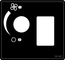
Cab Controls
For Machines with a Cab
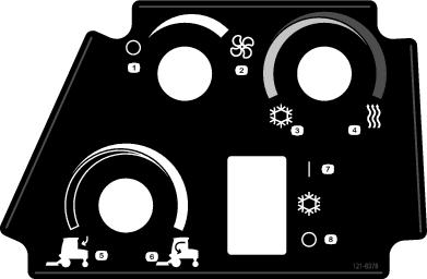
Air-Recirculation Control
The air-recirculation control sets the cab to either recirculate the air in the cabin or to draw air into the cabin from outside (Figure 13).
-
Set it to recirculate the air when using the air-conditioning.
-
Set it to draw air in when using the heater or fan.
Fan-Control Knob
Rotate the fan-control knob to regulate the speed of the fan (Figure 13).
Temperature-Control-Knob
Rotate the temperature-control knob to regulate the air temperature in the cab (Figure 13).
Windshield-Wiper Switch
Use this switch to turn the windshield wipers on or off (Figure 13).
Air-Conditioning Switch
Use this switch to turn the air conditioning on or off (Figure 13).
Windshield Latch
Lift up the latches to open the windshield (Figure 14). Press in the latch to lock windshield to the OPEN position. Pull out and down on the latch to close and secure the windshield.
Rear Window Latch
Lift up the latches to open the rear window. Press in on the latch to lock the window in OPEN position. Pull out and down on the latch to close and secure the window (Figure 14).
Important: Close the rear window before opening the hood or damage may occur to the hood or rear window.
Note: Specifications and design are subject to change without notice.
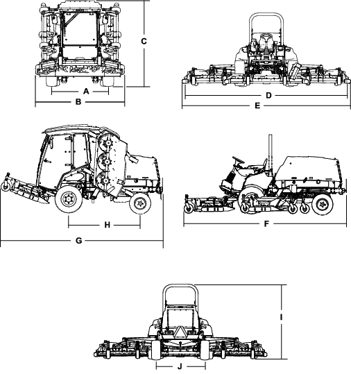
| Description | Figure 15 reference | Dimension or Weight | |
| Height with cab | C | 240 cm (94.5 inches) | |
| Height with roll bar | I | 216 cm (85 inches) | |
| Overall length | F | 442 cm (174 inches) | |
| Length for storage or transport | G | 434 cm (171 inches) | |
| Width of cut | |||
| overall | D | 488 cm (192 inches) | |
| front cutting unit | 234 cm (92 inches) | ||
| side cutting unit | 145 cm (57 inches) | ||
| front and one side cutting unit | 361 cm (142 inches) | ||
| Overall width | |||
| cutting units down | E | 506 cm (199 inches) | |
| cutting units up (transport position) | B | 251 cm (99 inches) | |
| Wheel base | H | 194 cm (76-1/2 inches) | |
| Wheel tread (tire center to center) | |||
| front | A | 159 cm (62.5 inches) | |
| rear | J | 142 cm (56 inches) | |
| Ground clearance | 25.4 cm (10 inches) | ||
| Net weight with cab | 3313 kg (7,304 lb) | ||
| Net weight with roll bar | 3044 kg (6,710 lb) | ||
Attachments/Accessories
A selection of Toro approved attachments and accessories is available for use with the machine to enhance and expand its capabilities. Contact your Authorized Service Dealer or authorized Toro distributor or go to www.Toro.com for a list of all approved attachments and accessories.
To ensure optimum performance and continued safety certification of the machine, use only genuine Toro replacement parts and accessories. Replacement parts and accessories made by other manufacturers could be dangerous, and such use could void the product warranty.
Operation
Note: Determine the left and right sides of the machine from the normal operating position.
Before Operation
Before Operation Safety
General Safety
This product is capable of amputating hands and feet and of throwing objects. Always follow all safety instructions to avoid serious personal injury.
-
Read and understand the contents of this Operator’s Manual before starting the engine.
-
Use your full attention while operating the machine. Do not engage in any activity that causes distractions; otherwise, injury or property damage may occur.
-
Do not operate the machine without all guards and other safety protective devices in place and functioning properly on the machine.
-
Keep your hands and feet away from rotating parts. Keep clear of the discharge opening.
-
Keep bystanders and children out of the operating area. Never allow children to operate the machine.
-
Shut off the engine, remove the key, and wait for all movement to stop before you leave the operator’s position. Allow the machine to cool before adjusting, servicing, cleaning, or storing it.
Improperly using or maintaining this machine can result in injury.
To reduce the potential for injury, comply with these safety instructions
and always pay attention to the safety-alert symbol , which means Caution, Warning,
or Danger—personal safety instruction. Failure to comply with
these instructions may result in personal injury or death.
Fuel Safety
-
Use extreme care in handling fuel. It is flammable and its vapors are explosive.
-
Extinguish all cigarettes, cigars, pipes, and other sources of ignition.
-
Use only an approved fuel container.
-
Do not remove the fuel cap or fill the fuel tank while the engine is running or hot.
-
Do not add or drain fuel in an enclosed space.
-
Do not store the machine or fuel container where there is an open flame, spark, or pilot light, such as on a water heater or other appliance.
-
If you spill fuel, do not attempt to start the engine; avoid creating any source of ignition until the fuel vapors have dissipated.
Checking the Engine-Oil Level
Before you start the engine and use the machine, check the oil level in the engine crankcase; refer to Checking the Engine-Oil Level.
Checking the Cooling System
Before you start the engine and use the machine, check the cooling system; refer to Checking the Engine-Cooling System.
Checking the Hydraulic System
Before you start the engine and use the machine, check the hydraulic system; refer to Checking the Hydraulic Lines and Hoses.
Filling the Fuel Tank
Fuel Tank Capacity
132 L (35 US gallons)
Fuel Specification
Important: Use only ultra-low sulphur diesel fuel. Fuel with higher rates of sulfur degrades the diesel oxidation catalyst (DOC), which causes operational problems and shortens the service life of engine components.Failure to observe the following cautions may damage the engine.
-
Never use kerosene or gasoline instead of diesel fuel.
-
Never mix kerosene or used engine oil with the diesel fuel.
-
Never keep fuel in containers with zinc plating on the inside.
-
Do not use fuel additives.
Petroleum Diesel
Cetane rating: 45 or higher
Sulfur content: Ultra-low sulfur (<15 ppm)
| Diesel fuel specification | Location |
| ASTM D975 | USA |
| No. 1-D S15 | |
| No. 2-D S15 | |
| EN 590 | European Union |
| ISO 8217 DMX | International |
| JIS K2204 Grade No. 2 | Japan |
| KSM-2610 | Korea |
-
Use only clean, fresh diesel fuel or biodiesel fuels.
-
Purchase fuel in quantities that can be used within 180 days to ensure fuel freshness.
Use summer-grade diesel fuel (No. 2-D) at temperatures above -7°C (20°F) and winter-grade fuel (No. 1-D or No. 1-D/2-D blend) below that temperature.
Note: Use of winter-grade fuel at lower temperatures provides lower flash point and cold flow characteristics which eases starting and reduces fuel filter plugging.Using summer-grade fuel above -7°C (20°F) contributes toward longer fuel pump life and increased power compared to winter-grade fuel.
Using Biodiesel
This machine can also use a biodiesel-blended fuel of up to B20 (20% biodiesel, 80% petrodiesel).
Sulfur content: Ultra-low sulfur (<15 ppm)
Biodiesel fuel specification: ASTM D6751 or EN14214
Blended fuel specification: ASTM D975, EN590, or JIS K2204
Important: The petroleum diesel portion must be ultra-low sulfur.
Observe the following precautions:
-
Biodiesel blends may damage painted surfaces.
-
Use B5 (biodiesel content of 5%) or lesser blends in cold weather.
-
Monitor seals, hoses, gaskets in contact with fuel as they may degrade over time.
-
Fuel filter plugging may occur for a time after you convert to biodiesel blends.
-
For more information on biodiesel, contact your authorized Toro distributor.
Adding Fuel
-
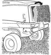
Park the machine on a level surface (Figure 16).
-
Shut off the engine, remove the key, and engage the parking brake.
-
Clean around the fuel-tank cap and remove the cap.
-
Add fuel and install the fuel-tank cap. Wipe up any spilled fuel.
Checking the Tire Pressure
The correct air pressure in the front tires is 220 kPa (32 psi) and the rear tires is 207 kPa (30 psi) as shown in Figure 17.
Important: Maintain pressure in all tires to ensure a good quality of cut and proper machine performance. Do not underinflate the tires.Check the air pressure in all the tires before operating the machine.Traction performance, including tire-slip control, is dependent on the ratio of the tire size between the front and rear tires. Use only genuine Toro tires.
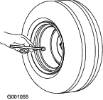
Checking the Caster Wheel Tire Pressure
The correct air pressure in the caster wheel tires is 340 kPa (50 psi).
Important: Maintain pressure in all tires to ensure a good quality of cut and proper machine performance. Do not underinflate the tires.Check the air pressure in all the tires before operating the machine.
Checking the Torque of the Wheel-Lug Nuts
| Maintenance Service Interval | Maintenance Procedure |
|---|---|
| After the first 10 hours |
|
| Every 250 hours |
|
Warning
Failure to maintain the proper torque of the wheel nuts could result in failure or loss of a wheel, and may result in personal injury.
Torque the front and rear-wheel nuts to 135 to 150 N·m (100 to 110 ft-lb) according to the maintenance schedule.
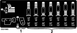
Adjusting the Height of Cut
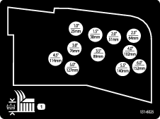
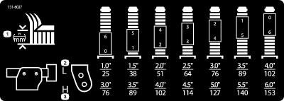
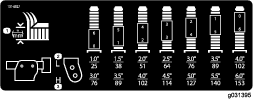
You can adjust the height of cut from 25 to 153 mm (1 to 6 inches) in 13 mm (1/2 inch) increments. To adjust the height of cut, position the caster-wheel axles in the upper or lower holes of the caster forks, add or remove an equal number of spacers from the caster forks, and adjust the rear chain (front deck only) to the desired holes.
Adjusting the Front Cutting Unit
-
Start the engine and raise the cutting units so you can change the height of cut.
-
Shut off the engine and remove the key after the cutting unit is raised.
-
Position the caster-wheel axles in the same holes in all of the caster forks; refer to the chart (Figure 18) to determine the correct holes for the setting.
Note: To prevent grass buildup between the wheel and the fork, operate the machine at the 76 mm (3 inches) height of cut or higher and install the axle bolt in the bottom caster-fork hole. When operating the machine at a height of cut lower than 76 mm (3 inches) and when you detect grass buildup, reverse the direction of the machine to pull any clippings away from the wheel and fork.
-
Using the supplied caster-cap wrench, loosen the tensioning cap and remove it from the caster-spindle shaft and slide the caster shaft out of the caster arm (Figure 19).
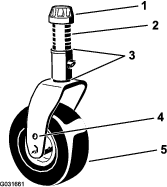
-
Slide the appropriate number of spacers onto the shaft to get the desired height of cut.
Note: Refer to the chart to determine the combinations of spacers for the setting (Figure 18).
Note: You may use the shims in any combination above or below the caster-arm hub (as required) to achieve the desired height of cut or deck level.
-
Push the caster shaft through the front caster arm.
-
Install the shims (as originally installed) and the remaining spacers onto the shaft (Figure 19).
-
Install the tensioning cap and tighten it with the supplied caster-cap wrench to secure the assembly (Figure 19).
-
Remove the hairpin cotter and clevis pin securing the height-of-cut chains to the rear of the cutting unit (Figure 20).
-
Mount the height-of-cut chains to the desired height-of-cut hole with the clevis pin and hairpin cotter (Figure 21).
Note: When mowing at a height of cut below 51 mm (2 inches), move the skids, gage wheels, and rollers to the highest holes.
Adjusting the Wing Cutting Units
-
Start the engine and raise the cutting units so you can change the height of cut.
-
Shut off the engine and remove the key after you raise the cutting unit.
-
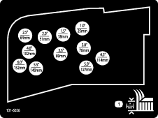
Position the caster-wheel axles in the same holes in all of the caster forks; refer to the chart to determine the correct holes for the height-of-cut setting (Figure 22).
Note: To prevent grass buildup between the wheel and the fork, operate the machine at the 76 mm (3 inches) height of cut or higher and install the axle bolt in the bottom caster-fork hole. When operating the machine at a height of cut lower than 76 mm (3 inches) and when you detect grass buildup, reverse the direction of the machine to pull any clippings away from the wheel and fork.
-
Using the supplied caster-cap wrench, loosen the tensioning cap and remove it from the caster-spindle shaft and slide the caster shaft out of the caster arm (Figure 23).
Note: You may use shims in any combination above or below the caster arm hub as required to achieve the desired height of cut or deck level.
-
5. Install 2 shims onto the shaft as originally installed and slide the appropriate number of spacers onto the shaft to get the desired height of cut.
-
Push the caster shaft through the caster arm.
-
Install the shims (as originally installed) and the remaining spacers onto the shaft.
-
Install the tensioning cap and tighten it with the supplied caster-cap wrench to secure the assembly.
Adjusting the Skids
Adjusting the Inner Skids
Mount the inner skids in the lower position when operating at heights of cut greater than 51 mm (2 inches) and in the higher position when operating at heights of cut lower than 51 mm (2 inches).
Adjust the inner skids (Figure 24).
Important: Torque the screw at the front of each inner skid to 9 to 11 N·m (80 to 100 in-lb).
Adjusting the Outer Skids
Mount the outer skids in the lower position when operating at heights of cut greater than 51 mm (2 inches) and in the higher position when operating at heights of cut lower than 51 mm (2 inches).
Note: When the outer skids become worn, you can switch them to the opposite sides of the mower by flipping them over. This allows you to use the outer skids longer before replacing them.
Adjust the outer skids (Figure 25).
Important: Torque the screw at the front of each outer skid to 9 to 11 N·m (80 to 100 in-lb).
Adjusting the Cutting Unit Anti-Scalp Rollers
Mount the roller in the lower position when operating at heights of cut greater than 51 mm (2 inches) and in a higher position when operating at heights of cut lower than 51 mm (2 inches).

Correcting a Mismatch Between the Cutting Units
Due to differences in grass conditions and the counterbalance setting of the traction unit, you should cut the grass and check the appearance before you begin mowing the entire area.
-
Set all cutting units to the desired height of cut; refer to Adjusting the Height of Cut.
-
Check and adjust the front and rear tire pressure.
Note: The correct air pressure in the front tires is 220 kPa (32 psi) and the rear tires is 207 kPa (30 psi).
-
Check and adjust all caster tire pressures to 340 kPa (50 psi).
-
Check the lift and counterbalance pressures with the engine throttle at HIGH IDLE using the test ports; refer to Inspecting the Hydraulic System Test Ports.
-
Check for bent blades; refer to Checking for a Bent Blade.
-
Cut grass in a test area to determine if all cutting units are mowing at the same height.
-
If you need to adjust a cutting unit, find a flat surface using a 2 m (6 ft) or longer straight edge to ensure that the surface is flat.
-
To ease measuring the blade plane, raise the height of cut to the highest position; refer to Adjusting the Height of Cut.
-
Lower the cutting units onto the flat surface and remove the covers from the tops of the cutting units.
Wing Cutting Units
-
Rotate the blade of each spindle until the ends face forward and backward.
-
For the outside blade spindle only, equally adjust the shims on the front caster forks to match the desired height of cut.
-
Measure from the floor to the front tip of the mowing blade.
-
Rotate the blade 180° and measure from the floor to the tip of the mowing blade.
Note: The rear of the blade should be 7.5 mm (0.3 inch) higher than the front.
Note: If you need to make an adjustment, adjust the shims on the rear caster forks.
Matching the Height of Cut Between Cutting Units
-
Position the blade side to side on the outside spindle of both wing cutting units.
-
Measure from the floor to the tip of the cutting edge on both units and compare the measurements.
Note: These numbers should be within 3 mm (1/8 inch) of each other. Make no adjustment at this time.
-
Position the blade side to side on the inside spindle of the wing cutting unit and the corresponding outside spindle of the front cutting unit.
-
Measure from the floor to the tip of the cutting edge on the inside edge of the wing cutting unit to the corresponding outside edge of the front cutting unit and compare.
Note: The wing cutting unit caster wheels should remain on the ground with counterbalance applied.
Note: If you need to make an adjustment to match the cut between the front and wing cutting unit, make them to the wing cutting units only.
-
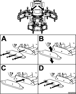
If the inside edge of the wing cutting unit is too high relative to the outside edge of the front cutting unit, remove 1 shim from the bottom of the front, inside caster arm on the wing cutting unit (Figure 28 and Figure 29).
Note: Check the measurement between the outside edges of both wing cutting units and the inside edge of the wing cutting unit to outside edge of the front cutting unit again.
-
If the inside edge is still too high, remove an additional shim from the bottom of the front, inside caster arm of the wing cutting unit and 1 shim from the front, outside caster arm of the wing cutting unit (Figure 28 and Figure 29).
-
If the inside edge of the wing cutting unit is too low relative to the outside edge of the front cutting unit, add 1 shim (1/8 inch) to the bottom of the front, inside caster arm on the wing cutting unit (Figure 28 and Figure 29).
Note: Check the measurement between the outside edges of both wing cutting units and the inside edge of the wing cutting unit to the outside edge of the front cutting unit again.
-
If the inside edge is still too low, add an additional shim to the bottom of front, inside caster arm of the wing cutting unit and 1 shim to the front, outside caster arm of the wing cutting unit.
-
Once the mowing height matches at the edges of the front and wing cutting units, verify that the cutting unit unit pitch is still 7.6 mm (0.3 inch).
Adjusting the Mirrors
For Machines with a Cab
Rear-View Mirror
While sitting in the seat, adjust the rear-view mirror to attain the best view out of the rear window. Pull the lever rearward to tilt the mirror to reduce the brightness and glare of light (Figure 30).
Side-View Mirrors
While sitting in the seat, have another person adjust the side-view mirrors to attain the best view around the side of the machine (Figure 30).
Aiming the Headlights
Model 31698 Only
-
Loosen the mounting nuts and position each headlight so that it points straight ahead.
Note: Tighten the mounting nut just enough to hold the headlight in position.
-
Place a flat piece of sheet metal over the face of the headlight.
-
Mount a magnetic protractor onto the plate.
-
While holding the assembly in place, carefully tilt the headlight downward 3° then tighten the nut.
-
Repeat this procedure on the other headlight.
Checking the Safety-Interlock Switches
Caution
If safety-interlock switches are disconnected or damaged, the machine could potentially operate unexpectedly, causing personal injury.
-
Do not tamper with or disable the safety systems.
-
Check the operation of the interlock switches daily and replace any damaged switches before operating the machine.
The machine safety-interlock system is designed to disable the traction drive when the operator leaves the seat with the traction pedal out of the NEUTRAL position. The deck drive also disengages under the same condition. However, you may get off the seat while the engine is running if the traction pedal is in the NEUTRAL position.
-
Drive the machine slowly to a large, open area.
-
Lower the cutting unit(s), shut off the engine, and engage the parking brake.
Checking the Traction Neutral Safety-Interlock Function
-
Move the traction pedal out of the NEUTRAL position and start the engine.
Note: The engine should not start. If it does start, there is a malfunction in the interlock system that you should correct before resuming operation.
-
Remove your foot from the traction pedal, start the engine, and engage the parking brake.
-
With the engine running, move the traction pedal out of the NEUTRAL position.
Note: The traction drive should not function. If it does function, there is a malfunction in the interlock system that you should correct before resuming operation.
Checking the PTO Safety-Interlock Function
-
Start the engine.
-
With the engine running, rise from the seat and engage the PTO.
Note: The PTO should not engage. If it does engage, there is a malfunction in the interlock system that you should correct before resuming operation.
-
Sit on the seat and disengage the PTO.
-
With the engine running, engage the PTO and rise from the seat.
Note: The PTO drive should disengage after a 1-second delay. If it does not shut off, there is a malfunction in the interlock system that you should correct before resuming operation.
-
Sit on the seat, disengage the PTO, and start the engine.
-
With the engine running, engage the PTO and raise each cutting unit individually.
Note: The blades of the raised cutting unit should stop. If the blades do not stop, there is a malfunction in the interlock system that you should correct before resuming operation.
Checking the Blade Stopping Time
| Maintenance Service Interval | Maintenance Procedure |
|---|---|
| Before each use or daily |
|
The blades of the cutting unit should come to a complete stop in approximately 5 seconds after you shut down the mower-deck-engagement switch.
Note: Ensure that the decks are lowered onto a clean section of turf or hard surface to avoid thrown dust and debris. To verify the stopping time, have someone stand back from the deck at least 6 m (20 ft) and watch the blades on 1 of the cutting units. Shut the cutting units down and record the time that it takes for the blades to come to a complete stop. If the time is greater than 7 seconds, adjust the braking valve; contact your authorized Toro distributor for assistance in making this adjustment.
During Operation
During Operation Safety
General Safety
-
The owner/operator can prevent and is responsible for accidents that may cause personal injury or property damage.
-
Wear appropriate clothing, including eye protection; long pants; substantial, slip-resistant footwear; and hearing protection. Tie back long hair and do not wear loose clothing or loose jewelry.
-
Do not operate the machine while ill, tired, or under the influence of alcohol or drugs.
-
Use your full attention while operating the machine. Do not engage in any activity that causes distractions; otherwise, injury or property damage may occur.
-
Before you start the engine, ensure that all drives are in neutral, the parking brake is engaged, and you are in the operating position.
-
Do not carry passengers on the machine and keep bystanders and children out of the operating area.
-
Operate the machine only in good visibility to avoid holes or hidden hazards.
-
Avoid mowing on wet grass. Reduced traction could cause the machine to slide.
-
Keep your hands and feet away from rotating parts. Keep clear of the discharge opening.
-
Look behind and down before backing up to be sure of a clear path.
-
Use care when approaching blind corners, shrubs, trees, or other objects that may obscure your vision.
-
Stop the blades whenever you are not mowing.
-
Stop the machine, remove the key, and wait for all moving parts to stop before inspecting the attachment after striking an object or if there is an abnormal vibration in the machine. Make all necessary repairs before resuming operation.
-
Slow down and use caution when making turns and crossing roads and sidewalks with the machine. Always yield the right-of-way.
-
Disengage the drive to the cutting unit, shut off the engine, remove the key, and wait for all movement to stop before adjusting the height of cut (unless you can adjust it from the operating position).
-
Operate the engine only in well-ventilated areas. Exhaust gases contain carbon monoxide, which is lethal if inhaled.
-
Never leave a running machine unattended.
-
Before you leave the operator’s position, do the following:
-
Park the machine on a level surface.
-
Disengage the power takeoff and lower the attachments.
-
Engage the parking brake.
-
Shut off the engine and remove the key.
-
Wait for all movement to stop.
-
-
Operate the machine only in good visibility. Do not operate the machine when there is the risk of lightning.
-
Do not use the machine as a towing vehicle.
-
Use accessories, attachments, and replacement parts approved by Toro only.
Rollover Protection System (ROPS) Safety
-
The ROPS is an integral and effective safety device.
-
Do not remove any of the ROPS components from the machine.
-
Ensure that the seat belt is attached to the machine.
-
Pull the belt strap over your lap and connect the belt to the buckle on the other side of the seat.
-
To disconnect the seat belt, hold the belt, press the buckle button to release the belt, and guide the belt into the auto-retract opening. Ensure that you can release the belt quickly in an emergency.
-
Check carefully for overhead obstructions and do not contact them.
-
Keep the ROPS in safe operating condition by thoroughly inspecting it periodically for damage and keeping all the mounting fasteners tight.
-
Replace damaged ROPS components. Do not repair or alter them.
Additional ROPS Safety for Machines with a Cab or a Fixed Roll Bar
-
A cab installed by Toro is a roll bar.
-
Always wear your seat belt.
Slope Safety
-
Slopes are a major factor related to loss of control and rollover accidents, which can result in severe injury or death. You are responsible for safe slope operation. Operating the machine on any slope requires extra caution.
-
Evaluate the site conditions to determine if the slope is safe for machine operation, including surveying the site. Always use common sense and good judgment when performing this survey.
-
Review the slope instructions listed below for operating the machine on slopes and to determine whether you can operate the machine in the conditions on that day and at that site. Changes in the terrain can result in a change in slope operation for the machine.
-
Avoid starting, stopping, or turning the machine on slopes. Avoid making sudden changes in speed or direction. Make turns slowly and gradually.
-
Do not operate a machine under any conditions where traction, steering, or stability is in question.
-
Remove or mark obstructions such as ditches, holes, ruts, bumps, rocks, or other hidden hazards. Tall grass can hide obstructions. Uneven terrain could overturn the machine.
-
Be aware that operating the machine on wet grass, across slopes, or downhill may cause the machine to lose traction. Loss of traction to the drive wheels may result in sliding and a loss of braking and steering.
-
Use extreme caution when operating the machine near drop-offs, ditches, embankments, water hazards, or other hazards. The machine could suddenly roll over if a wheel goes over the edge or the edge caves in. Establish a safety area between the machine and any hazard.
-
Identify hazards at the base of the slope. If there are hazards, mow the slope with a pedestrian-controlled machine.
-
If possible, keep the cutting unit(s) lowered to the ground while operating on slopes. Raising the cutting unit(s) while operating on slopes can cause the machine to become unstable.
-
Use extreme caution with grass-collection systems or other attachments. These can change the stability of the machine and cause a loss of control.
Starting the Engine
-
Ensure that the parking brake is engaged.
-
Remove your foot from the traction pedal and ensure that it is in the NEUTRAL position.
-
Turn the ignition key to the RUN position.
-
When the glow indicator dims, turn the ignition key to the START position.
-
Release the key immediately when the engine starts and allow it to return to the RUN position.
-
Allow the engine to warm up at low speed (without load) for 3 to 5 minutes, then actuate the throttle switch to attain the desired engine speed.
Important: The starter motor automatically disengages after 30 seconds to prevent premature starter motor failure. If the engine fails to start after 30 seconds, turn the key to the OFF position, check the controls and procedures again, wait 2 minutes, and repeat the starting procedure.
Note: When the hydraulic-fluid temperature is below 4°C (40°F), the machine operates in a warm-up mode; limiting the engine speed to 1,650 rpm and preventing traction-drive operation in High range. When the fluid temperature reaches 4°C (40°F), the warm-up mode disables.
Shutting Off the Engine
-
Set the throttle switch to the LOW-IDLE position.
-
Move the PTO switch to the OFF position.
-
Engage the parking brake.
-
Rotate the ignition key to the OFF position.
-
Remove the key from the switch to prevent accidental starting.
Important: Allow the engine to idle for 5 minutes before shutting it off after a full-load operation. Failure to do so may lead to turbo-charger complications.
Raising or Lowering the Cutting Units
Raising the Cutting Units
-
While sitting in the operator’s seat, start the engine.
Note: Whenever you are running the machine at under 2,000 rpm (e.g., when you are running the engine at low idle or transporting the machine into or out of a building), you will not be able raise all the cutting units at once. Instead, you can only raise 1 cutting unit at a time.
-
Push the deck-lift switches rearward to raise the decks.
Lowering the Decks
-
Using the handle, unhook the latches holding the decks in the raised position.
-
While sitting in the operator’s seat, turn the ignition key to the RUN position (Figure 31).
-
Push the deck-lift switches forward to lower the decks.
Diesel Particulate Filter Regeneration
The diesel particulate filter (DPF) is part of the exhaust system. The diesel-oxidation catalyst of the DPF reduces harmful gasses and the soot filter removes soot from the engine exhaust.
The DPF regeneration process uses heat from the engine exhaust to incinerate the soot accumulated on the soot filter, converting the soot to ash, and clears the channels of the soot filter so that filtered engine exhaust flows out the DPF.
The engine computer monitors the accumulation of soot by measuring the back pressure in the DPF. If the back pressure is too high, soot is not incinerating in the soot filter through normal engine operation. To keep the DPF clear of soot, remember the following:
-
Passive regeneration occurs continuously while the engine is running—run the engine at full engine speed when possible to promote DPF regeneration.
-
If the back pressure in the DPF is too high or a reset regeneration has not occurred for 100 hours, the engine computer signals you through the InfoCenter when reset regeneration is running.
-
Allow the reset regeneration process to complete before shutting off the engine.
Operate and maintain your machine with the function of the DPF in mind. Engine load at high idle (full throttle) engine speed generally produces adequate exhaust temperature for DPF regeneration.
Important: Minimize the amount of time that you idle the engine or operate the engine at low-engine speed to help reduce the accumulation of soot in the soot filter.
DPF Soot Accumulation
-
Over time, the diesel particulate filter accumulates soot in the soot filter. The computer for the engine monitors the soot level in the DPF.
-
When enough soot accumulates, the computer informs you that it is time to regenerate the DPF.
-
DPF regeneration is a process that heats the DPF to convert the soot to ash.
-
In addition to the warning messages, the computer reduces the power produced by the engine at different soot-accumulation levels.
DPF Ash Accumulation
-
The lighter ash is discharged through the exhaust system; the heavier ash collects in the soot filter.
-
Ash is a residue of the regeneration process. Over time, the diesel particulate filter accumulates ash that does not discharge with the engine exhaust.
-
The computer for the engine calculates the amount of ash accumulated in the DPF.
-
When enough ash accumulates, the engine computer sends information to the InfoCenter in the form of an engine fault to indicate the accumulation of ash in the DPF.
-
The fault messages indicate that it is time to service the DPF.
-
In addition to the warnings, the computer reduces the power produced by the engine at different ash-accumulation levels.
| Indication Level | Fault Code | Engine Speed Reduction | Engine Power Rating | Recommended Action |
|---|---|---|---|---|
| Level 1: Engine Warning |
 | None | The computer de-rates the engine power to 85%. | Service the DPF; refer to Servicing the Diesel-Oxidation Catalyst (DOC) and the Soot Filter |
| Level 2: Engine Warning |
| None | The computer de-rates the engine power to 50%. | Service the DPF; refer to Servicing the Diesel-Oxidation Catalyst (DOC) and the Soot Filter |
| Level 3: Engine Warning |
 | Engine speed at maximum torque + 200 rpm | The computer de-rates the engine power to 50%. | Service the DPF; refer to Servicing the Diesel-Oxidation Catalyst (DOC) and the Soot Filter |
Types of Diesel Particulate Filter Regeneration
| Type of Regeneration | Conditions that cause DPF regeneration | DPF description of operation |
|---|---|---|
| Passive | Occurs during normal operation of the machine at high-engine speed or high-engine load | • The InfoCenter does not display an icon indicating passive regeneration. |
| • During passive regeneration, the DPF processes high-heat exhaust gasses, oxidizing harmful emissions, and burning soot to ash. | ||
| Refer to Passive DPF Regeneration. | ||
| Assist | Occurs because of low-engine speed, low-engine load, or after the computer detects the DPF is becoming obstructed with soot | • The InfoCenter does not display an icon indicating assist regeneration. |
| • During assist regeneration, the engine computer adjusts the engine settings to raise the exhaust temperature. | ||
| Refer to Assist DPF Regeneration. | ||
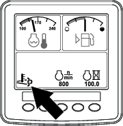
| Reset | Occurs every 100 hours | • When the high exhaust-temperature icon  is displayed in the InfoCenter,
a regeneration is in progress. is displayed in the InfoCenter,
a regeneration is in progress. |
| Also occurs after assist regeneration only if the computer detects that assist regeneration did not sufficiently reduce the soot level | ||
| • During reset regeneration, the engine computer adjusts the engine settings to raise the exhaust temperature. | ||
| Refer to Reset Regeneration. |
| Type of Regeneration | Conditions that cause DPF regeneration | DPF description of operation |
|---|---|---|
| Parked | Occurs because the computer detects back pressure in the DPF due to soot buildup | • When the reset-standby/parked
or recovery regeneration icon  or ADVISORY #188 displays
in the InfoCenter, a regeneration is requested. or ADVISORY #188 displays
in the InfoCenter, a regeneration is requested. |
| Also occurs because the operator initiates a parked regeneration | ||
| May occur because you set the InfoCenter to inhibit reset regeneration and continued operating the machine, adding more soot when the DPF already needs a reset regeneration | • Perform the parked regeneration as soon as possible to avoid needing a recovery regeneration. | |
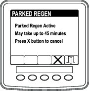
| May result from using the incorrect fuel or engine oil | • A parked regeneration requires 30 to 60 minutes to complete. | |
| • You must have at least a 1/4 tank of fuel in the tank. | ||
| • You must park the machine to perform a parked regeneration. | ||
| Refer to Parked or Recovery Regeneration. | ||
| Recovery | Occurs because the operator ignored requests for a parked regeneration and continued operating the machine, adding more soot to the DPF | • When the reset-standby/parked or recovery
regeneration icon or ADVISORY #190 displays
in the InfoCenter, a recovery regeneration is requested. |
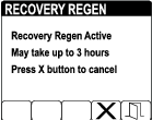
| • A recovery regeneration requires up to 3 hours to complete. | ||
| • You must have at least a 1/2 tank of fuel in the machine. | ||
| • You must park the machine to perform a recovery regeneration. | ||
| Refer to Parked or Recovery Regeneration. |
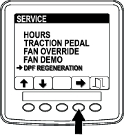
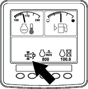
Accessing the DPF Regeneration Menus
Accessing the DPF Regeneration Menus
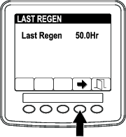
Time Since Last Regeneration
-
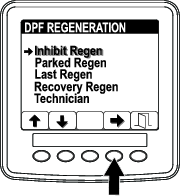
Access the DPF Regeneration menu, and press buttons 1 or 2 to scroll to the LAST REGEN option (Figure 36).
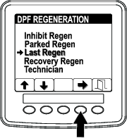
-
Press the button 4 to select the Last Regen entry (Figure 36).
-
Use the LAST REGEN field (Figure 37) to determine how many hours you have run the engine since the last reset, parked, or recovery regeneration.
-
Press button 4 to return to the DPF regeneration screen or press button 5 to exit the service menu and return to the home screen.
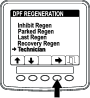
Technician Menu
Important: For operating convenience, you may decide to perform a parked regeneration before the soot load reaches 100%, provided the engine has run more than 50 hours since the last successful reset, parked, or recovery regeneration.
Use the technician menu to view the current state of engine regeneration control and view the reported soot level.
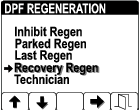
-
Access the DPF Regeneration menu, and press buttons 1 or 2 to scroll down to the TECHNICIAN option (Figure 38).
-
Press the button 4 to select the Technician entry (Figure 38)
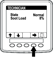
The state and soot load information displays.
-
Use the DPF operation table to understand the current state of DPF operation (Figure 39).
.
DPF Operation Table
State Description Normal The DPF is in normal-operating mode—passive regeneration. Assist Regen The engine computer is performing an assist regeneration. Reset Stby The engine computer is trying to run a reset regeneration, but 1 of the following conditions prevents regeneration: The regen inhibit setting is set to ON. The exhaust temperature is too low for regeneration. Reset Regen The engine computer is running a reset regeneration. Parked Stby The engine computer is requesting that you run a parked regeneration. Parked Regen You initiated a parked regeneration request and the engine computer is processing the regeneration. Recov. Stby The engine computer is requesting that you run a recovery regeneration. Recov. Regen You initiated a recovery regeneration request and the engine computer is processing the regeneration. -
View the soot load which is measured as the percentage of soot in the DPF(Figure 40); refer to the soot-load table.
Note: The soot load value varies as the machine is operated and DPF regeneration occurs.
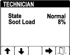
Soot-Load Table
Important Soot Load Values Regeneration State 0% to 5% Minimum soot load range 78% The engine computer performs an assist regeneration. 100% The engine computer automatically requests a parked regeneration. 122% The engine computer automatically requests a recovery regeneration.
-
-
Press button 4 to return to the technician screen or press button 5 to exit the service menu and return to the home screen.
Passive DPF Regeneration
-
Passive regeneration occurs as part of normal engine operation.
-
While operating the machine, run the engine at full-engine speed and high load when possible to promote DPF regeneration.
Assist DPF Regeneration
-
The engine computer adjusts engine settings to raise the exhaust temperature.
-
While operating the machine, run the engine at full engine speed and high load when possible to promote DPF regeneration.
Reset Regeneration
Caution
The exhaust temperature is hot (approximately 600°C (1,112°F) during DPF regeneration. Hot exhaust gas can harm you or other people.
-
Never operate the engine in an enclosed area.
-
Make sure that there are no flammable materials around the exhaust system.
-
Never touch a hot exhaust system component.
-
Never stand near or around the exhaust pipe of the machine.
-
The high exhaust-temperature icon
displays in the InfoCenter
(Figure 41). -
The engine computer adjusts engine settings to raise the exhaust temperature.
Important: The high exhaust-temperature icon indicates that the exhaust temperature discharged from of your machine may be hotter than during regular operation.
-
While operating the machine, run the engine at full engine speed and high load when possible to promote DPF regeneration.
-
The icon displays in the InfoCenter while the reset regeneration is processing.
-
Whenever possible, do not shut off the engine or reduce engine speed while the reset regeneration is processing.
Important: Whenever possible, allow the machine to complete the reset regeneration process before shutting off the engine.
Periodic Reset Regeneration
If the engine has not completed a successful Reset, Parked, or Recovery regeneration in the previous 100 hours of engine operation, the engine computer will attempt to perform a reset regeneration.
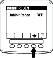
Setting the Inhibit Regen
Reset Regeneration Only
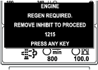
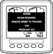
Note: If you set the InfoCenter to inhibit regeneration, the InfoCenter displays ADVISORY #1215 (Figure 42) every 15 minutes while the engine requests a reset regeneration.
A reset regeneration produces the elevated engine exhaust. If you are operating the machine around trees, brush, tall grass, or other temperature-sensitive plants or materials, you can use the Inhibit Regen setting to prevent the engine computer from performing a reset regeneration.
Important: When you shut off the engine and start it again, the inhibit regen setting defaults to OFF.
Allowing a Reset Regeneration
The InfoCenter displays the high exhaust-temperature icon when the reset regeneration
is in process.
Note: If INHIBIT REGEN is set to ON, the InfoCenter displays ADVISORY #1215 (Figure 45). Press any button to set inhibit regeneration setting to OFF and continue with the reset regeneration.
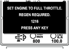
Note: If the engine exhaust temperature is too low, the InfoCenter displays ADVISORY #1216 (Figure 46) to inform you to set the engine to full throttle (high idle).
Note: When the reset regeneration completes, the high exhaust-temperature disappears from the InfoCenter
screen.
Parked or Recovery Regeneration
-
When the engine computer requests either a parked regeneration or a recovery regeneration, the regeneration request icon (Figure 47) displays in the InfoCenter.
-
The machine does not automatically perform a parked regeneration or a recovery regeneration, you must run the regeneration through the InfoCenter.
Parked Regeneration Messages
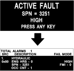
When a parked regeneration is requested by the engine computer the following messages display in the InfoCenter:
-
Engine warning SPN 3720, FMI 16 (Figure 48)
-
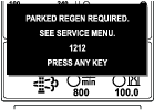
Parked regeneration required ADVISORY #1212 (Figure 49)
Note: Advisory #1212 displays every 15 minutes.
-
If you do not perform a parked regeneration within 2 hours, the InfoCenter displays parked regeneration required—power takeoff disabled ADVISORY #1213 (Figure 50).
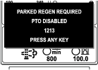
Important: Perform a parked regeneration to restore the PTO function; refer to Preparing to Perform a Parked or Recovery Regeneration and Parked or Recovery Regeneration.
Note: The Home screen displays the power takeoff disabled ADVISORY #1213 every 15 minutes until you perform a parked regeneration or the engine computer requires you to perform a recovery regeneration.
Recovery Regeneration Messages
When a recovery regeneration is requested by the engine computer, the following messages display in the InfoCenter:
Recovery regeneration required—power takeoff disabled ADVISORY #1214 (Figure 51)
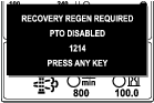
Important: Perform a recovery regeneration to restore the PTO function; refer to Preparing to Perform a Parked or Recovery Regeneration and Parked or Recovery Regeneration.
Note: The Home screen displays the power takeoff disabled ADVISORY #1214 every 15 minutes until you perform a recovery regeneration.
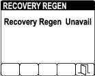
DPF Status-Limitation
-
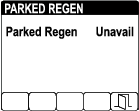
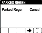
If the engine computer requests a recovery regeneration or is processing a recovery regeneration and you select the PARKED REGEN option (Figure 52), Parked Regen screen locks (unavailable).

-
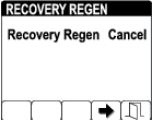
If the engine computer has not requested a recovery regeneration and you select the RECOVERY REGEN option (Figure 53), Recovery Regen screen locks (unavailable).
Preparing to Perform a Parked or Recovery Regeneration
-
Ensure that the machine has fuel in the tank for the type of regeneration you are performing:
-
Parked Regeneration: Ensure that you have 1/4 tank of fuel before performing the parked regeneration.
-
Recovery Regeneration: Ensure that you have 1/2 tank of fuel before performing the recovery regeneration.
-
-
Move the machine outside to an area away from combustible materials.
-
Park the machine on a level surface.
-
Ensure that the traction control or motion-control levers are in the NEUTRAL position.
-
If applicable, shut off the PTO, and lower the cutting units or accessories.
-
Engage the parking brake.
-
Set the throttle to the low IDLE position.
Performing a Parked or Recovery Regeneration
Caution
The exhaust temperature is hot (approximately 600°C (1,112°F) during DPF regeneration. Hot exhaust gas can harm you or other people.
-
Never operate the engine in an enclosed area.
-
Make sure that there are no flammable materials around the exhaust system.
-
Never touch a hot exhaust system component.
-
Never stand near or around the exhaust pipe of the machine.
Important: The computer of the machine cancels DPF regeneration if you increase the engine speed from low idle or release the parking brake.
-
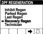
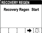
Access the DPF Regeneration menu, and press buttons 1 or 2 to scroll down to the PARKED REGEN option or the RECOVERY REGEN option (Figure 54).
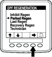
-
Press the button 4 to select the Parked Regen entry or the Recovery Regen entry (Figure 55).
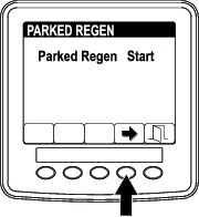
-
On the Parked Regen menu or Recovery Regen menu, press the button 4 to start the regeneration (Figure 55).
-
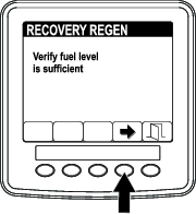
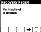
At the VERIFY FUEL LEVEL screen, verify that you have 1/4 tank of fuel if you are performing the parked regeneration or 1/2 tank of fuel if you are performing the recovery regeneration, and press the button 4 to continue (Figure 56).
-
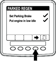
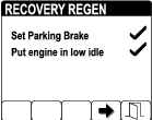
At the DPF checklist screen, verify that the parking brake is engaged, that the engine speed is set to low idle, press the button 4 to continue (Figure 57).
-
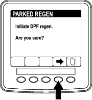
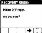
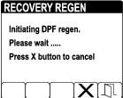
At the INITIATE DPF REGEN screen, press the button 4 to continue (Figure 58).
-
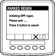
The InfoCenter displays the INITIATING DPF REGEN message (Figure 59).
Note: If needed, press button 4 to cancel the regeneration process.
-
The InfoCenter displays the time to complete message (Figure 60).
Note: If needed, press button 4 to cancel the regeneration process.
-
The engine computer checks the engine state and fault information. The InfoCenter may display the following messages found in the table that follows:
Check Message and Corrective Action Table
 Parked Regen
 Recovery Regen
Check Message: Less that 50 hours since last regeneration—press any key. Corrective Action: Exit the regeneration menu and run the machine until the time since last regeneration is greater than 50 hours; refer to Time Since Last Regeneration.  Parked RegenRecovery Regen
Check Message: Diagnostic trouble code active 1220—press any key. Corrective Action: Troubleshoot the engine fault and retry DPF regeneration. 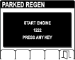 Parked Regen
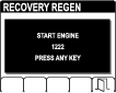 Recovery Regen
Check Message: Start engine 1222—press any key. Corrective Action: Start and run the engine.  Parked Regen
 Recovery Regen
Check Message: Engine not warm enough 1221—press any key. Corrective Action: Run the engine to warm the coolant temperature to 60°C (140°F). 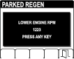 Parked Regen
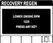 Recovery Regen
Check Message: Lower engine RPM 1223—press any key. Corrective Action: Change the engine speed to low idle.  Parked Regen
 Recovery Regen
Check Message: Regen rejected by engine 1217—press any key. Corrective Action: Troubleshoot the engine computer condition and retry DPF regeneration. -
The InfoCenter displays the home screen and the regeneration acknowledge icon (Figure 61) appears in the lower right corner of the screen as the regeneration processes.
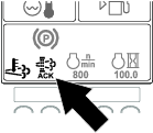
Note: While the DPF regeneration runs, the InfoCenter displays the high exhaust-temperature icon
. -
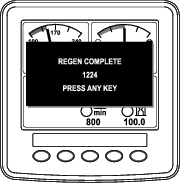
When the engine computer completes a parked or recovery regeneration, the InfoCenter displays ADVISORY #1224 (Figure 62). Press any button to exit to the home screen.
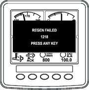
Note: If the regeneration fails to complete, the InfoCenter displays Advisory #1218 (Figure 63). Press any button to exit to the home screen.
Canceling a Parked or Recovery Regeneration
Use the Parked Regen Cancel or Recovery Regen Cancel setting to cancel a running parked or recovery regeneration process.
-
Access the DPF Regeneration menu, and press buttons 1 or 2 to scroll down to the PARKED REGEN option or the RECOVERY REGEN option (Figure 64).
-
Press the button 4 to cancel a Parked Regen or cancel a Recovery Regen (Figure 65).
Note: If you do not want to cancel the parked or recovery regeneration, press button 5 to exit the regeneration screen.
Understanding the Operating Characteristics of the Machine
Practice driving the machine, as it has a hydrostatic transmission, and its characteristics may differ from other turf-maintenance machines.
With Toro Smart Power™, you do not have to listen to the engine speed in heavy load conditions. Smart Power prevents the engine from bogging down in heavy cutting conditions by automatically controlling the machine speed and optimizing cutting performance.
If Toro Smart Power™ is disabled, you must regulate the traction pedal to keep the engine speed (rpm) high and constant. This must be performed so that enough power is maintained for the traction unit and implement while operating. Decrease the ground speed as the load on the implement increases, and increase the ground speed as the load decreases.
Allow the traction pedal to move backward as the engine speed (rpm) decreases, and press the pedal slowly as the engine speed increases. By comparison, when driving between work areas, with no load and the cutting unit raised, set the throttle in the highest position and press the traction pedal slowly, but fully, to attain maximum ground speed.
Before stopping the engine, disengage all controls and decrease the engine speed to LOW IDLE (1,000 rpm). Turn the ignition key to the OFF position to shut off the engine.
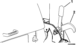
Before transporting the machine, raise the cutting units and secure the transport latches on the wing cutting unit (Figure 66).
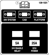
Understanding the 12 V and
This machine is designed with 2 voltage systems: 12 V and 24 V.
The 12 V system powers all functions of the machine, except for the engine-cooling fans and hydraulic-cooling fans. The 2 large 12 V batteries at the rear, right corner of the machine are connected in parallel to provide 12 V nominal. The 12 V engine alternator charges these batteries.
The 24 V system powers the engine-cooling fans and hydraulic-cooling fans. The 2 small 12 V batteries at the rear, left corner of the machine are connected in series to provide 24 V nominal. The 24 V alternator charges these batteries.
The battery-disconnect switch is located at the rear, right side of the machine. This switch can be used to disconnect power from the batteries during service or maintenance procedures.
Automatic-Reversing Fan Cycle
The hydraulic-fan speed is controlled by hydraulic-fluid temperature. The radiator-fan speed is controlled by the engine-coolant temperature. A reverse cycle automatically initiates both fans when either the engine coolant or hydraulic-fluid temperature reaches a certain point. This reversal blows debris off the screens, lowering the engine and hydraulic-fluid temperatures (Figure 67). Additionally, the radiator fans perform a reverse cycle every 21 minutes regardless of the coolant temperature.
Operating Tips
Operating the Machine
-
Start the engine and run it at the HALF IDLE position until it warms up. Move the engine-speed switch to HIGH IDLE, lift the cutting units, disengage the parking brake, press the forward traction pedal, and carefully drive to an open area.
-
Practice moving forward and reverse, and starting and stopping the machine. To stop the machine, remove your foot from the traction pedal and let it return to NEUTRAL or press down on the reverse pedal.
Note: When going downhill in the machine, you may need to use the reverse pedal to stop.
-
Practice driving around obstacles with the cutting units up and down. Be careful when driving between narrow objects so that you do not damage the machine or cutting units.
-
Always drive slowly in rough areas.
-
If an obstacle is in the way, lift the cutting units to mow around it.
-
When transporting the machine from 1 work area to another, shut off the PTO, raise the cutting units to the fully upward position, press the mow/transport switch to the TRANSPORT position, engage the transport latches, and place the throttle in the FAST position.
Changing Mowing Patterns
Change mowing patterns often to minimize a poor after-cut appearance from repeatedly mowing in the same direction.
Understanding Counterbalance
The counterbalance system maintains hydraulic back pressure on the cutting unit lift cylinders. This pressure improves traction by transferring the cutting unit weight to the mower-drive wheels. The counterbalance pressure has been set at the factory to an optimal balance of after-cut appearance and traction capability in most turf conditions.
Decreasing the counterbalance setting can produce a more stable cutting unit, but can decrease the traction capability. Increasing the counterbalance setting can increase the traction capability, but may result in a poor after-cut appearance. Refer to the machine Service Manual for your traction unit for instructions to adjust the counterbalance pressure.
Resolving After-Cut Appearance
Refer to the After-cut Appearance Troubleshooting Guide available at www.Toro.com.
Using Proper Mowing Techniques
-
To begin cutting, engage the cutting units, then approach the mowing area slowly.
-
To achieve the professional straight-line cut and striping that is desirable for some applications, find a tree or other object in the distance and drive straight toward it.
-
As soon as the front cutting units reach the edge of the mowing area, perform a teardrop-shaped turn to quickly line up for your next pass.
-
Bolt-in mulching baffles are available for the cutting units. The mulching baffles perform well when you maintain turf on a regular schedule to avoid removing more than 25 mm (1 inch) of growth per cutting. When you cut too much growth with the mulching baffles installed, the after-cut appearance may deteriorate and the observed power to cut the turf increases. The mulching baffles also perform well for shredding leaves in the fall.
Selecting the Proper Height-of-Cut Setting
Remove approximately one-third of the grass blade when mowing. In exceptionally lush and dense grass, you may need to raise the height-of-cut to the next setting (Figure 68).
Adjusting the Mower-Deck Pitch
Mower-deck pitch is the difference in height-of-cut from the front of the blade plane to the back of the blade plane. Use a blade pitch of 7.6 mm (0.3 inch). A pitch larger than 7.6 mm (0.3 inch) results in less power required, larger clippings, and a poorer quality of cut. A pitch less than 7.6 mm (0.3 inch) results in more power required, smaller clippings, and a better quality of cut.
Maximizing the Air Conditioner Performance
-
To limit solar heating, park the machine in a shaded area or leave the doors open in direct sun.
-
Ensure that the air-conditioning screen is clean.
-
Ensure that the air-conditioning-condenser fins are clean.
-
Operate the air-conditioner blower at the mid-speed setting.
-
Ensure that there is a continuous seal between the roof and the headliner and correct it as needed.
-
Measure the air temperature at the front, center vent in the headliner. This should typically stabilize at less than or equal to 10°C (50°F).
-
Refer to the Service Manual for additional information.
After Operation
General Safety
-
Shut off the engine, remove the key, and wait for all movement to stop before you leave the operator’s position. Allow the machine to cool before adjusting, servicing, cleaning, or storing it.
-
Clean grass and debris from the cutting units, mufflers, and engine compartment to help prevent fires. Clean up oil or fuel spills.
-
If the cutting units are in the transport position, use the positive mechanical lock (if available) before you leave the machine unattended.
-
Allow the engine to cool before storing the machine in any enclosure.
-
Remove the key and shut off the fuel (if equipped) before storing or hauling the machine.
-
Never store the machine or fuel container where there is an open flame, spark, or pilot light, such as on a water heater or on other appliances.
-
Maintain and clean the seat belt(s) as necessary
Understanding the Audible Alarm
Note: This alarm is a reminder to prevent the battery from being discharged.
An audible alarm sounds when the following conditions occur:
-
The engine is shut off.
-
The key is in the run position.
-
The operator is out of the seat.
Pushing or Towing the Machine
Important: Do not push or tow the machine faster than 3 to 4.8 km/h (2 to 3 mph). If you push or tow at a faster speed, internal transmission damage may occur.The bypass valves must be open whenever you push or tow the machine.
-
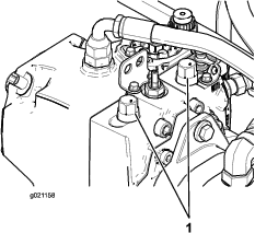
Raise the hood and locate the bypass valves on the pump.
-
Loosen both tow valves on the hydrostatic transmission.
-
Rotate each valve 3 turns counter-clockwise to open the valve and allow the fluid to bypass internally.
-
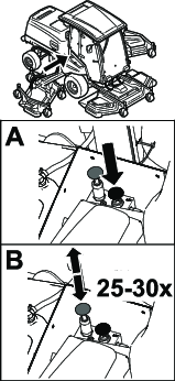
Manually release the automatic parking brake using the bypass valve and plunger as shown in Figure 70.
-
Push or tow the machine.
-
Finish pushing or towing the machine and close the bypass valve. Torque the valve to 70 N∙m (52 ft-lb).
Note: The manual parking-brake release automatically resets when you start the engine or pull the bypass-valve knob up.
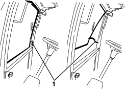
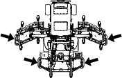
Identifying the Tie-Down Points
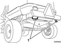
Hauling the Machine
-
Remove the key and shut off the fuel (if equipped) before storing or hauling the machine.
-
Use care when loading or unloading the machine into a trailer or a truck.
-
Use full-width ramps for loading the machine into a trailer or a truck.
-
Tie the machine down securely.
Maintenance
Note: Determine the left and right sides of the machine from the normal operating position.
Important: Refer to your engine owner's manual for additional maintenance procedures.
Important: If you are performing maintenance on the machine and run the engine with an engine exhaust-extraction duct, set the inhibit regen setting to ON; refer to Setting the Inhibit Regen.
Maintenance Safety
-
Before you leave the operator’s position, do the following:
-
Park the machine on a level surface.
-
Disengage the power takeoff and lower the attachments.
-
Engage the parking brake.
-
Shut off the engine and remove the key.
-
Wait for all movement to stop.
-
-
If you leave the key in the switch, someone could accidently start the engine and seriously injure you or other bystanders. Remove the key from the switch before you perform any maintenance.
-
Allow machine components to cool before performing maintenance.
-
If the cutting units are in the transport position, use the positive mechanical lock (if equipped) before you leave the machine unattended.
-
If possible, do not perform maintenance while the engine is running. Keep away from moving parts.
-
Support the machine with jack stands whenever you work under the machine.
-
Carefully release pressure from components with stored energy.
-
Keep all parts of the machine in good working condition and all hardware tightened, especially blade-attachment hardware.
-
Replace all worn or damaged decals.
-
To ensure safe, optimal performance of the machine, use only genuine Toro replacement parts. Replacement parts made by other manufacturers could be dangerous, and such use could void the product warranty.
Recommended Maintenance Schedule(s)
| Maintenance Service Interval | Maintenance Procedure |
|---|---|
| After the first 10 hours |
|
| After the first 50 hours |
|
| Before each use or daily |
|
| Every 50 hours |
|
| Every 100 hours |
|
| Every 250 hours |
|
| Every 400 hours |
|
| Every 500 hours |
|
| Every 800 hours |
|
| Every 1,000 hours |
|
| Every 1,500 hours |
|
| Every 2,000 hours |
|
| Every 3,000 hours |
|
| Every 6,000 hours |
|
| Before storage |
|
| Every 2 years |
|
Pre-Maintenance Procedures
Using the Battery-Disconnect Switch
Open the hood to access the battery-disconnect switch.
Turn the battery-disconnect switch to the ON or OFF position to perform the following:
-
To energize the machine electrically, rotate the battery-disconnect switch clockwise to the ON position (Figure 74).
-
To de-energize the machine electrically, rotate the battery-disconnect switch counterclockwise to the OFF position (Figure 74).
Important: Do not turn the battery-disconnect switch to the OFF position while the engine is running. Ensure that the machine is shut off before turning the battery-disconnect switch to the OFF position, as you may cause damage to the engine and/or machine.
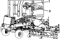
Raising the Machine
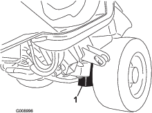
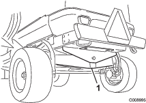
Removing and Installing the Inner-Wing-Deck Covers
Removing the Inner-Wing-Deck Covers
-
Lower the wing deck onto a level surface.
-
Disengage the cover latch.
-
Remove the bolt securing the belt cover (if equipped).
-
Lift the rear and inside cover edges off the mounting posts (Figure 77).
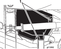
-
While lifting the cover, slide it toward the traction unit approximately 2.5 cm (1 inch) to disengage the outer-cover edge from the deck (Figure 78).
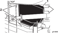
-
Lift the front edge and guide it between the lift arm and the roller to remove it (Figure 79).
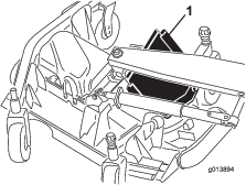
Installing the Inner-Wing-Deck Covers
-
Lower the wing deck onto a level surface.
-
Slide the cover into position by guiding the rear edge between the lift arm and the roller.
-
While sliding the cover away from the traction unit, guide the outside edge under the front and rear brackets on the deck.
-
Align the deck mounting posts with the holes in the cover and lower the cover into position.
-
Install the bolt securing the belt cover (if equipped).
-
Engage the deck-cover latch.
Lubrication
Greasing the Bearings and Bushings
| Maintenance Service Interval | Maintenance Procedure |
|---|---|
| Every 50 hours |
|
The machine has grease fittings that you must lubricate regularly with No. 2 lithium grease. Also, lubricate the machine immediately after every washing.
Traction Unit
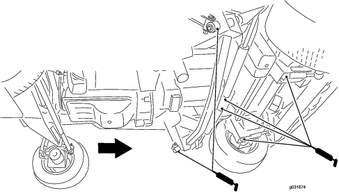
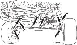
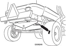
Front Cutting Unit
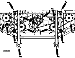
Front Lift Assemblies
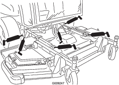
Wing Cutting Units (Each Wing)
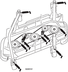
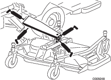
Engine Maintenance
Important: Do not directly contact the engine-control unit (ECU) or electrical connectors with water, as this may cause damage; refer to Figure 87 for the ECU and electrical connections location.
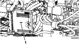
Engine Safety
-
Shut off the engine and remove the key before checking the oil or adding oil to the crankcase.
-
Do not change the governor speed or overspeed the engine.
Servicing the Air Cleaner
Check the air-cleaner body for damage that could cause an air leak and replace it if it is damaged. Check the entire intake system for leaks, damage, or loose hose clamps. Also, inspect the rubber intake-hose connections at the air cleaner and turbocharger to ensure that the connections are complete.
Service the air-cleaner filter only when the “Check Air Filter” message is displayed on the InfoCenter (Figure 88). Changing the air filter before it is necessary only increases the chance of dirt entering the engine when you remove the filter.
Ensure that the cover is seated correctly and seals with the air-cleaner body.
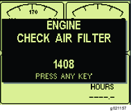
Servicing the Air-Cleaner Cover
| Maintenance Service Interval | Maintenance Procedure |
|---|---|
| Every 50 hours |
|
Check the air-cleaner body for damage which could cause an air leak. Replace a damaged air cleaner body.
Clean the air-cleaner cover (Figure 89).
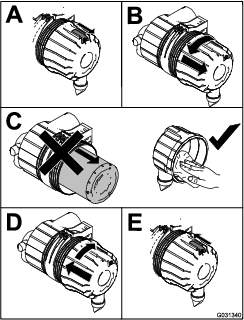
Servicing the Air-Cleaner Filter Elements
| Maintenance Service Interval | Maintenance Procedure |
|---|---|
| Every 250 hours |
|
| Every 500 hours |
|
The air-intake system on this machine is continuously monitored by an air-restriction sensor that will displays an advisory when you need to replace the filter. Do not replace the elements until this occurs.
Important: Replace the secondary filter element only every 3 primary filter services. Do not remove the secondary element when cleaning or replacing the primary element. The inner element prevents dust from entering the engine when you service the primary element.
Important: Do not operate the engine without the air-cleaner elements as this would allow foreign material to enter the engine and damage it.
-
Release the latches securing the air-cleaner cover to the air-cleaner body (Figure 90).
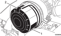
-
Remove the cover from the air-cleaner body.
-
Before removing the filter, use low-pressure air (275 kPa or 40 psi, clean and dry) to help remove large accumulations of debris packed between the outside of the primary filter and the canister.
Note: Avoid using high-pressure air that could force dirt through the filter into the intake. This cleaning process prevents debris from migrating into the intake when the primary filter is removed.
-
Remove the primary filter (Figure 91).
Note: Do not clean the used element due to the possibility of damage to the filter media.
Note: Replace the secondary filter every 3 primary filter services (Figure 92).
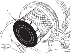
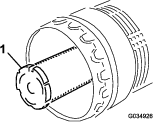
-
Inspect the new filter for shipping damage, checking the sealing end of the filter and the body.
Important: Do not use a damaged element.
-
Insert the new filter by applying pressure to the outer rim of the element to seat it in the canister.
Important: Do not apply pressure to the flexible center of the filter, as this may damage the filter.
-
Clean the dirt-ejection port located in the removable cover.
-
Remove the rubber outlet valve from the cover, clean the cavity, and replace the outlet valve.
-
Install the cover orienting the rubber outlet valve in a downward position—approximately between the 5 o’clock and 7 o’clock position when viewed from the end.
-
Secure the cover latches.
Servicing the Engine Oil
Oil Specification
Use high-quality, low-ash engine oil that meets or exceeds the following specifications:
-
API service category CJ-4 or higher
-
ACEA service category E6
-
JASO service category DH-2
Important: Using engine oil other than API CJ-4 or higher, ACEA E6, or JASO DH-2 may cause the diesel particulate filter to plug or cause engine damage.
Use the following engine oil viscosity grade:
-
Preferred oil: SAE 15W-40 (above 0°F)
-
Alternate oil: SAE 10W-30 or 5W-30 (all temperatures)
Toro Premium Engine Oil is available from your authorized Toro distributor in either 15W-40 or 10W-30 viscosity grades. See the Parts Catalog for part numbers.
Checking the Engine-Oil Level
| Maintenance Service Interval | Maintenance Procedure |
|---|---|
| Before each use or daily |
|
The engine is shipped with oil in the crankcase; however, the oil level must be checked before and after the engine is first started.
Important: Check the engine oil daily. If the engine-oil level is above the Full mark on the dipstick, the engine oil may be diluted with fuel;If the engine oil level is above the Full mark, change the engine oil.
The best time to check the engine oil is when the engine is cool before it has been started for the day. If it has already been run, allow the oil to drain back down to the sump for at least 10 minutes before checking. If the oil level is at or below the Add mark on the dipstick, add oil to bring the oil level to the Full mark. Do not overfill the engine with oil.
Important: Keep the engine-oil level between the upper and lower limits on the dipstick; the engine may fail if you run it with too much or too little oil.
Check the engine-oil level; refer to Figure 93.
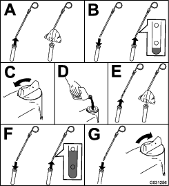
Note: When using different oil, drain all old oil from the crankcase before adding new oil.
Crankcase Oil Capacity
10.4 L (11 US qt) with the filter
Changing the Engine Oil and Engine-Oil Filter
| Maintenance Service Interval | Maintenance Procedure |
|---|---|
| Every 500 hours |
|
Note: Change the engine oil and filter more frequently when the operating conditions are extremely dusty or sandy.
-
Start the engine and let it run 5 minutes to allow the oil to warm up.
-
Park the machine on a level surface, engage the parking brake, lower the cutting deck, shut off the engine, and remove the key.
-
Change the engine oil as shown in Figure 94.
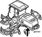
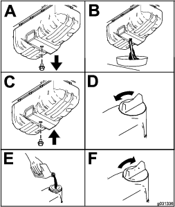
-
Change the engine-oil filter (Figure 95).
Note: Ensure that the oil-filter gasket touches the engine, and then an extra 3/4 turn is completed.
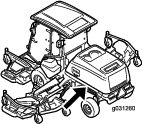
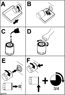
Adjusting the Engine-Valve Clearance
| Maintenance Service Interval | Maintenance Procedure |
|---|---|
| Every 1,000 hours |
|
Refer to your engine owner’s manual for the adjustment procedure.
Cleaning the Engine EGR Cooler
| Maintenance Service Interval | Maintenance Procedure |
|---|---|
| Every 1,500 hours |
|
For information on cleaning the engine EGR cooler, refer to your engine operator’s manual.
Inspecting the Engine Crankcase-Breather System
| Maintenance Service Interval | Maintenance Procedure |
|---|---|
| Every 1,500 hours |
|
For information on inspecting the engine crankcase-breather system, refer to your engine operator’s manual.
Checking and Replacing Fuel Hoses and Engine-Coolant Hoses
| Maintenance Service Interval | Maintenance Procedure |
|---|---|
| Every 2,000 hours |
|
For information on checking and replacing fuel hoses and engine-coolant hoses, refer to your engine operator’s manual.
Lapping or Adjusting the Engine Intake and Exhaust Valves
| Maintenance Service Interval | Maintenance Procedure |
|---|---|
| Every 2,000 hours |
|
For information on lapping or adjusting the engine intake and exhaust valves, refer to your engine owner’s manual.
Inspecting and Cleaning Engine-Emission-Control Components and Turbocharger
| Maintenance Service Interval | Maintenance Procedure |
|---|---|
| Every 3,000 hours |
|
For information on inspecting and cleaning the engine-emission-control components, refer to your engine operator’s manual.
Servicing the Diesel-Oxidation Catalyst (DOC) and the Soot Filter
| Maintenance Service Interval | Maintenance Procedure |
|---|---|
| Every 6,000 hours |
|
-
If advisory message displays in the InfoCenter, the DPF is nearing the recommended point for servicing the diesel-oxidation catalyst and the soot filter.

-
If engine faults , , or in the InfoCenter (Figure 97) display in the InfoCenter, clean the soot filter using the steps that follow:
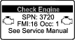
-
Refer to the Engine section in the Service Manual for information on disassembling and assembling the diesel-oxidation catalyst and the soot filter of the DPF.
-
Refer to your authorized Toro distributor for diesel-oxidation catalyst and the soot filter replacement parts or service.
-
Contact your authorized Toro distributor to have them reset the engine ECU after you install a clean DPF.
-
Fuel System Maintenance
Servicing the Fuel System
| Maintenance Service Interval | Maintenance Procedure |
|---|---|
| Every 3,000 hours |
|
Draining the Fuel Tank
| Maintenance Service Interval | Maintenance Procedure |
|---|---|
| Every 800 hours |
|
| Before storage |
|
In addition to the listed service interval, drain and clean the tank if the fuel system becomes contaminated or if you are storing the machine for an extended period. Use clean fuel to flush out the tank.
Inspecting the Fuel Lines and Connections
| Maintenance Service Interval | Maintenance Procedure |
|---|---|
| Every 400 hours |
|
Inspect the fuel lines for deterioration, damage, or loose connections.
Servicing the Water Separator
| Maintenance Service Interval | Maintenance Procedure |
|---|---|
| Before each use or daily |
|
| Every 400 hours |
|
Draining the Water Separator
-
Place a drain pan under the fuel filter.
-
Loosen the drain valve on the bottom of the filter (Figure 98).
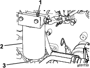
-
Tighten the valve after draining.
Replacing the Water-Separator Element
-
Place a clean container under the water separator.
-
Drain some fuel by loosening the vent plug and opening the drain valve (Figure 98).
-
Clean the area where the filter element mounts to the head.
-
Remove the filter element.
-
Apply a coating of clean fuel or engine oil to the new O-ring and element seal.
-
Install the new filter canister by hand until the gasket contacts the filter head, then tighten it an additional 1/2 turn.
Note: Do not use tools.
-
Close the drain plug.
-
With the vent plug still loosened, turn the ignition key to the RUN position (do not start the engine) so that the electric fuel pump can fill the new filter.
-
When fuel flows from the vent plug, close the vent plug, start the engine, and check for leaks.
Note: Correct as necessary with the engine off.
Replacing the Fuel Filter Element
| Maintenance Service Interval | Maintenance Procedure |
|---|---|
| Every 500 hours |
|
-
Clean the area around the fuel-filter head (Figure 99).
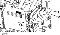
-
Remove the filter and clean the filter-head-mounting surface (Figure 99).
-
Lubricate the filter gasket with clean, lubricating engine oil; refer to the engine owner's manual (included with the machine) for additional information.
-
Install the dry filter canister, by hand, until the gasket contacts the filter head, then rotate it an additional 1/2 turn.
-
Turn the ignition key to the RUN position so that the electric fuel pump can fill the fuel-filter canister.
-
Start the engine and check for fuel leaks around the filter head.
Electrical System Maintenance
Electrical System Safety
-
Disconnect the battery before repairing the machine. Disconnect the negative terminal first and the positive last. Connect the positive terminal first and the negative last.
-
Charge the battery in an open, well-ventilated area, away from sparks and flames. Unplug the charger before connecting or disconnecting the battery. Wear protective clothing and use insulated tools.
Checking the Battery Condition
| Maintenance Service Interval | Maintenance Procedure |
|---|---|
| Every 50 hours |
|
Important: Before welding on the machine, disconnect the negative cable from the battery to prevent damage to the electrical system. Also, you must disconnect the engine, InfoCenter, and machine controllers before welding on the machine.
Note: Keep the terminals and the entire battery case clean, because a dirty battery discharges slowly. To clean the battery, wash the entire case with a solution of baking soda and water. Rinse with clear water. Coat the battery posts and cable connectors with Grafo 112X (skin-over) grease (Toro Part No. 505-47) or petroleum jelly to prevent corrosion.
Locating the Fuses
Important: If you are installing an auxiliary accessory to the machine, the only approved locations to source power are at the traction-unit fuse block (Figure 104) or the cab-fuse block (Figure 106). A maximum of 10 A is available from either location. Contact your authorized Toro distributor for assistance.
Note: Shut off the engine and remove the key before removing the fuses.
The traction-unit fuses (Figure 100) are located in the power-center console behind the seat (Figure 101).
Additional traction-unit fuses (Figure 102) are located on the rear, right side of the machine (Figure 103).
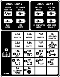
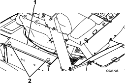

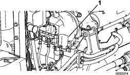
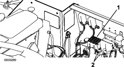
The cab fuses (Figure 105) are located in the fuse box on the cab headliner (Figure 106).
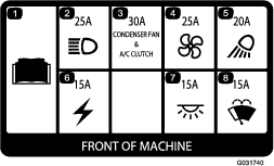
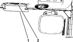
Charging the Batteries
Warning
Charging the batteries produces gasses that can explode.
Do not smoke near the battery, and keep sparks and flames away from the batteries.
Note: This procedure is for charging the 12 V system.
Important: Keep the batteries fully charged. This is especially important to prevent battery damage when the temperature is below 32°F (0°C).
-
Perform the pre-maintenance procedure; refer to Pre-Maintenance Procedures.
-
Clean the exterior of the battery case and the battery posts.
Note: Connect the leads of the battery charger to battery posts before connecting the charger to the electrical source.
-
Remove the covers from the jump posts (Figure 107).
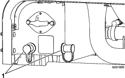
-
Connect the positive lead of the battery charger to the positive jump post (Figure 108).
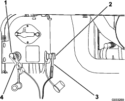
-
Connect the negative lead of the battery charger to the negative jump post (Figure 108).
-
Connect the battery charger to the electrical source, and charge the battery according to the Battery-charging Table that follows.
Important: Do not overcharge the battery.
Battery-charger Table
Charger setting Charging time 4 to 6 A 30 minutes 25 to 30 A 10 to 15 minutes -
When the batteries are fully charged, unplug the charger from the electrical source, then disconnect the charger leads from the jump posts (Figure 108).
Jump-Starting the Machine
Warning
Jump-starting the battery can produce gasses that can explode.
Do not smoke near the battery and keep sparks and flames away from battery.
Note: This procedure requires 2 people to perform. Ensure that the person making the connections wears the proper face protection, protective gloves, and clothing.
-
Park the machine on a level surface, engage the parking brake, lower the cutting deck, and shut off the engine.
-
Sit in the operator seat and have the other person make the connections.
Note: Ensure that the jumper battery is a 12V battery.
Important: If you are using another machine for power, ensure that the 2 machines are not touching each other.
-
Remove the covers from the jump posts (Figure 107).
-
Connect the positive (+) jumper cable to the positive jump post (Figure 109).
-
Connect the negative (-) jumper cable to the negative jump post (Figure 109).
-
Start the engine.
Important: If the engine starts and then stops, do not operate the starter motor until the starter motor stops turning. Do not operate the starter motor for more than 30 seconds at one time. Wait 30 seconds before operating the starter motor to cool the motor.
-
When the engine starts, have the other person disconnect the negative (-) jumper cable from the negative jump post and then disconnect the positive (+) jumper cable (Figure 109).
Removing the Batteries
-
Open the hood and turn the battery-disconnect switch to the OFF position.
-
Remove the three 3 flange screws from each side of the rear bumper as shown in Figure 110.
-
Loosen the remaining flange screws securing the rear bumper to the frame and pivot the bumper downward.
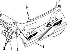
-
Loosen the knobs and remove both side shrouds (Figure 111).
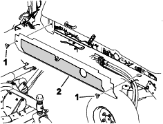
-
Remove the 6 flange screws securing rear shroud to the frame and remove the rear shroud (Figure 112).
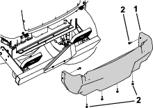
-
Remove the fasteners that secure the battery cover to the machine and remove the cover (Figure 113).
Note: Make note of how and where the battery cables are installed.
-
Loosen and remove the battery cables from the batteries.
-
Remove the fasteners that secure the battery-hold downs.
-
Carefully remove the batteries from the machine (Figure 113).
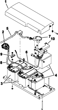
Installing the Batteries
-
Secure the batteries with the hold downs (Figure 113).
-
Install the battery cables.
-
Position the battery cover in place and secure it with the removed fasteners.
-
Install the rear shroud (Figure 112).
-
Install the side shrouds (Figure 111).
-
Raise the rear bumper into position and install the flange screws. Tighten all the flange screws securing the rear bumper to the frame (Figure 110).
-
Turn the battery-disconnect switch to the ON position.
Drive System Maintenance
Calibrating the Traction Pedal
| Maintenance Service Interval | Maintenance Procedure |
|---|---|
| Every 1,000 hours |
|
Contact your autorized Toro distributor or refer to the Toro Service Manual for assistance.
Adjusting the Traction-Pedal Angle
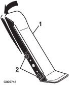
Checking the Rear Wheel Toe-In
| Maintenance Service Interval | Maintenance Procedure |
|---|---|
| Every 1,000 hours |
|
-
With the rear tires in a straight position, measure the outside distance (at axle height) at the front and rear of the rear tires (Figure 115).
Note: The front measurement should be 0 to 3 mm (0 to 0.12 inch) greater than the rear measurement.
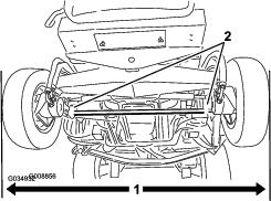
-
To adjust the toe-in, loosen the clamps at both ends of the tie rods (Figure 115).
-
Rotate the tie-rod to move the front of the tire inward or outward.
-
Once you achieve the correct toe-in, tighten the tie-rod clamps.
Cooling System Maintenance
Cooling System Safety
-
Swallowing engine coolant can cause poisoning; keep out of reach from children and pets.
-
Discharge of hot, pressurized coolant or touching a hot radiator and surrounding parts can cause severe burns.
-
Always allow the engine to cool at least 15 minutes before removing the radiator cap.
-
Use a rag when opening the radiator cap, and open the cap slowly to allow steam to escape.
-
-
Do not operate the machine without the covers in place.
-
Keep your fingers, hands and clothing clear of rotating fan and drive belt.
Checking the Engine-Cooling System
| Maintenance Service Interval | Maintenance Procedure |
|---|---|
| Before each use or daily |
|
| Every 100 hours |
|
The capacity of the system on a machine without a cab is 10.4 L (13.5 US qt) and with a cab is 17 L (18 US qt).
Recommended coolant: Ethelyne glycol anti-freeze and water (50/50 blend).
Danger
The rotating fans and drive belts can cause personal injury.
-
Do not operate the machine without the covers in place.
-
Keep your fingers, hands, and clothing clear of the rotating fan and drive belt.
-
Shut off the engine, remove the key, and turn the battery-disconnect switch to the OFF position before performing maintenance.
Caution
If the engine has been running, the pressurized, hot coolant can escape and cause burns.
-
Do not open the radiator cap when the engine is running.
-
Use a rag when opening the radiator cap, and open the cap slowly to allow steam to escape.
-
Carefully remove the radiator cap and expansion-tank cap (Figure 116).
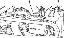
-
Check the coolant level in the radiator (Figure 116).
Note: When cool, the radiator should be filled to the top of the filler neck and the expansion tank filled to the Full mark.
-
If the coolant is low, add the recommended replacement coolant to the expansion tank to the Full mark.
Note: Do not use water only or alcohol/methanol-based coolants.
-
Install the radiator cap and expansion-tank cap.
Cleaning the Cooling Systems
| Maintenance Service Interval | Maintenance Procedure |
|---|---|
| Before each use or daily |
|
Perform the pre-maintenance procedure; refer to Maintenance Safety.
Important: Do not use water to clean the radiator core or hydraulic-fluid-cooler core. Cleaning the radiator core or hydraulic-fluid-cooler core with water can promote premature corrosion and damage to components.
Cleaning the Radiator
-
Raise the hood to the fully-open position.
-
Pivot the engine-cooling fans rearward of the radiator and lock the prop rod into the notch (Figure 117).
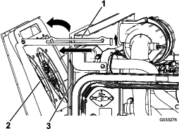
-
Using clean, compressed air, blow the debris from the engine side rearward to clean the radiator core.
-
Pivot the engine-cooling fans forward and lock the prop rod into the notch (Figure 118).

Cleaning the Hydraulic-Fluid Cooler
-
Raise the hood to the fully-open position.
-
Pivot the hydraulic-cooling fans upward and lock the prop rod into the notch (Figure 119).
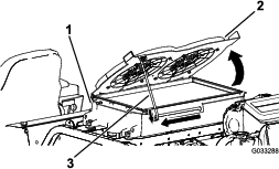
-
Using clean, compressed air, blow the debris from the engine side upward to clean the cooling core.
-
Pivot the hydraulic-cooling fans downward and lock the prop rod into the notch (Figure 120).
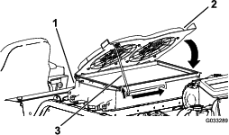
Changing the Engine-Cooling-
| Maintenance Service Interval | Maintenance Procedure |
|---|---|
| Every 2,000 hours |
|
The capacity of the system on a machine without a cab is 10.4 L (13.5 US qt) and with a cab is 17 L (18 US qt).
-
Perform the pre-maintenance procedure; refer to Pre-Maintenance Procedures.
-
Remove the radiator cap.
-
With the radiator drain hose placed in a drain pan, open the drain valve on the radiator hose and drain the fluid into a drain pan (Figure 121).

-
Close the valve on the radiator drain hose (Figure 121).
-
Fill the radiator with coolant until the coolant level even with the lip of the filler port (Figure 122).
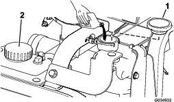
-
Install the radiator cap.
-
Remove the coolant hose from the engine-oil cooler (Figure 123).
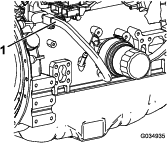
-
After draining the engine coolant, close the drain valve on the radiator drain hose and connect the coolant hose.
-
Remove the cap of the expansion tank and fill it to the Low mark with engine coolant. Install the cap.
-
Start and run the engine until it reaches operating temperature.
-
Check the engine-coolant level; refer to Checking the Engine-Cooling System.
-
Add coolant to the expansion tank to bring the coolant level to the Full mark.
-
Check all engine-coolant-hose connections for leaks.
Belt Maintenance
Servicing the 12 V Alternator Belt
| Maintenance Service Interval | Maintenance Procedure |
|---|---|
| After the first 50 hours |
|
| Every 250 hours |
|
Refer to the engine owner's manual (included with the machine) for the servicing procedure.
Servicing the 24 V Alternator Belt and AC Compressor Belt
| Maintenance Service Interval | Maintenance Procedure |
|---|---|
| After the first 10 hours |
|
| Every 1,000 hours |
|
The AC compressor and 24 V alternator belt uses a spring-loaded tensioner that is pre-set at the factory. Refer to the Toro Service Manual for the servicing procedure.
Replacing the Blade-Drive Belts
| Maintenance Service Interval | Maintenance Procedure |
|---|---|
| Every 50 hours |
|
| Every 1,000 hours |
|
The blade-drive belt, tensioned by the spring-loaded idler pulley, is very durable. However, after many hours of use, the belt will show signs of wear. Signs of a worn belt are squealing when the belt is rotating, blades slipping when cutting grass, frayed edges, burn marks, and cracks. Replace the belt if any of these signs occur.
Replacing the Front Cutting-Unit Belts
-
Lower the cutting unit to the floor.
-
Remove the belt covers from the top of the cutting unit and set the covers aside.
-
On the front deck, center position, loosen the jam nuts on the idler pulley stop screw and thread the stop screw into the bracket (Figure 124).
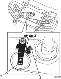
-
Using a ratchet wrench or similar tool, move each wing-deck idler pulley away from the drive belt to release the belt tension and allow the belt to slip off the wing-deck pulley (Figure 124).
-
Remove the bolts securing the hydraulic motor to the cutting unit (Figure 125).
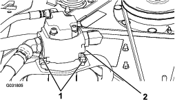
-
Lift the motor off the cutting unit and lay it on top of the cutting unit.
-
Remove the old belt from around the spindle pulleys and idler pulley.
-
Route the new belt around the spindle pulleys and idler-pulley assembly (Figure 126).
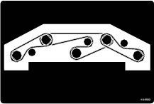
-
Adjust the stop screw on the idler pulley and tighten the jam nuts.
-
Install the belt covers.
Replacing the Wing Cutting-Unit Belts
Note: To remove the lower belt, you must remove the upper belt first.
-
Lower the cutting unit to the floor.
-
Remove the belt covers from the top of the cutting unit and set the covers aside.
-
Remove the bolts securing the hydraulic motor to the cutting unit (Figure 125).
-
Lift the motor off the cutting unit and lay it on top of the cutting unit.
-
Using a ratchet wrench or similar tool, move the idler pulleys away from the drive belt to release the belt tension and allow the belt to slip off the pulleys (Figure 127).
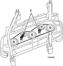
-
Remove the old belt from around the spindle pulleys and idler pulley.
-
Route the new belt around the spindle pulleys and idler-pulley assembly (Figure 128 and Figure 129).
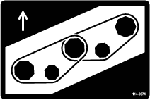
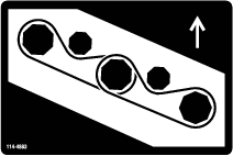
Hydraulic System Maintenance
Hydraulic System Safety
-
Seek immediate medical attention if fluid is injected into skin. Injected fluid must be surgically removed within a few hours by a doctor.
-
Ensure that all hydraulic-fluid hoses and lines are in good condition and all hydraulic connections and fittings are tight before applying pressure to the hydraulic system.
-
Keep your body and hands away from pinhole leaks or nozzles that eject high-pressure hydraulic fluid.
-
Use cardboard or paper to find hydraulic leaks.
-
Safely relieve all pressure in the hydraulic system before performing any work on the hydraulic system.
Hydraulic Fluid Specifications
The reservoir is filled at the factory with high-quality hydraulic fluid. Check the level of the hydraulic fluid before you first start the engine and daily thereafter; refer to Checking the Hydraulic Fluid.
Recommended hydraulic fluid: Toro PX Extended Life Hydraulic Fluid; available in 19 L (5 US gallon) pails or 208 L (55 US gallon) drums.
Note: A machine using the recommended replacement fluid requires less frequent fluid and filter changes.
Alternative hydraulic fluids: If Toro PX Extended Life Hydraulic Fluid is not available, you may use another conventional, petroleum-based hydraulic fluid having specifications that fall within the listed range for all the following material properties and that it meets industry standards. Do not use synthetic fluid. Consult with your lubricant distributor to identify a satisfactory product.
Note: Toro does not assume responsibility for damage caused by improper substitutions, so use products only from reputable manufacturers who will stand behind their recommendation.
| Material Properties: | ||
| Viscosity, ASTM D445 | cSt @ 40°C (104°F) 44 to 48 | |
| Viscosity Index ASTM D2270 | 140 or higher | |
| Pour Point, ASTM D97 | -37°C to -45°C (-34°F to -49°F) | |
| Industry Specifications: | Eaton Vickers 694 (I-286-S, M-2950-S/35VQ25 or M-2952-S) | |
Note: Many hydraulic fluids are almost colorless, making it difficult to spot leaks. A red dye additive for the hydraulic fluid is available in 20 ml (0.67 fl oz) bottles. A bottle is sufficient for 15 to 22 L (4 to 6 US gallons) of hydraulic fluid. Order Part No. 44-2500 from your authorized Toro distributor.
Important: Toro Premium Synthetic Biodegradable Hydraulic Fluid is the only synthetic biodegradable fluid approved by Toro. This fluid is compatible with the elastomers used in Toro hydraulic systems and is suitable for a wide-range of temperature conditions. This fluid is compatible with conventional mineral oils, but for maximum biodegradability and performance, the hydraulic system should be thoroughly flushed of conventional fluid. The oil is available in 19 L (5 US gallon) pails or 208 L (55 US gallon) drums from your authorized Toro distributor.
Hydraulic Fluid Capacity
The capacity is 62.7 L (16.6 US gallons).
Checking the Hydraulic Fluid
| Maintenance Service Interval | Maintenance Procedure |
|---|---|
| Before each use or daily |
|
-
Perform the pre-maintenance procedure; refer to Pre-Maintenance Procedures.
-
On the right side of the machine, raise the access cover to expose the hydraulic-tank cap (Figure 130).
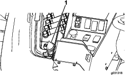
-
Clean the area around the filler neck and cap of the hydraulic tank (Figure 130).
-
Remove the cap from the filler neck.
-
Remove the dipstick from the filler neck and wipe it with a clean rag. Insert the dipstick into the filler neck, then remove it and check the fluid level (Figure 131).
Note: The fluid level should be within the safe operating range on the dipstick.

-
If the level is low, add the appropriate fluid to raise the level to the upper mark.
-
Install the dipstick and cap onto the filler neck.
-
Close the cover.
Changing the Hydraulic Fluid
| Maintenance Service Interval | Maintenance Procedure |
|---|---|
| Every 800 hours |
|
| Every 2,000 hours |
|
| Every 2 years |
|
-
Park the machine on a level surface, engage the parking brake, lower the cutting deck, shut off the engine, and remove the key.
-
Place a large drain pan under the hydraulic-fluid tank.
-
Remove the hydraulic-tank cap and dipstick.
-
Remove the drain plug from the bottom of the tank and let the hydraulic fluid flow into the pan (Figure 132).
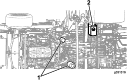
-
Install the drain plug when the hydraulic fluid stops draining.
-
Fill the reservoir with hydraulic fluid; refer to Checking the Hydraulic Fluid.
Important: Use only the hydraulic fluids specified. Other fluids could cause system damage.
-
Install the reservoir dipstick and cap.
-
Start the engine and use all of the hydraulic controls to distribute hydraulic fluid throughout the system.
Note: Also, check for leaks, then shut off the engine.
-
Check the fluid level and add enough to raise the level to the Full mark on the dipstick.
Note: Do not overfill.
Changing the Hydraulic Filters
| Maintenance Service Interval | Maintenance Procedure |
|---|---|
| Every 800 hours |
|
| Every 1,000 hours |
|
If the hydraulic fluid becomes contaminated, contact your authorized Toro distributor because the system must be flushed. Contaminated fluid looks milky or black when compared to clean fluid.
Use Toro replacement filters (Part No. 86-6110 for the left side of the machine and Part No. 75-1310 for the right side of the machine).
Important: Using any other filter may void the warranty on some components.
-
Park the machine on a level surface, engage the parking brake, lower the cutting deck, shut off the engine, and remove the key.
-
Clean the area around the filter-mounting areas.
-
Place a drain pan under the filter and remove the filter (Figure 132).
-
Lubricate the new filter gasket and fill the filter with hydraulic fluid.
-
Ensure that each filter-mounting area is clean and screw the filter on until the gasket contacts the mounting plate; then tighten the filter an additional 1/2 turn.
-
Fill the reservoir with hydraulic fluid; refer to Checking the Hydraulic Fluid.
Important: Use only the hydraulic fluids specified. Other fluids could cause system damage.
-
Install the reservoir dipstick and cap.
-
Start the engine and use all of the hydraulic controls to distribute hydraulic fluid throughout the system.
Note: Also, check for leaks, then shut off the engine.
-
Check the fluid level and add enough to raise the level to the Full mark on the dipstick.
Note: Do not overfill.
Checking the Hydraulic Lines and Hoses
| Maintenance Service Interval | Maintenance Procedure |
|---|---|
| Every 2 years |
|
Warning
Hydraulic fluid escaping under pressure can penetrate skin and cause injury.
-
Seek immediate medical help if fluid is injected into skin.
-
Make sure that all hydraulic-fluid hoses and lines are in good condition and all hydraulic connections and fittings are tight before applying pressure to the hydraulic system.
-
Keep your body and hands away from pinhole leaks or nozzles that eject high-pressure hydraulic fluid.
-
Use cardboard or paper to find hydraulic leaks.
-
Safely relieve all pressure in the hydraulic system before performing any work on the hydraulic system.
Inspect the hydraulic lines and hoses daily for leaks, kinked lines, loose mounting supports, wear, loose fittings, weather deterioration, and chemical deterioration. Make all necessary repairs before operating the machine.
Inspecting the Hydraulic System Test Ports
The test ports are used to test the pressure in the hydraulic circuits. Contact your authorized Toro distributor or refer to the Toro Service Manual for assistance.
Cutting Unit Maintenance
Pivoting (Tilting) the Front Cutting-Unit to the Upright Position
Note: Although not needed for normal maintenance procedures, you can pivot (tilt) the front cutting unit to an upright position.
-
Raise the front cutting unit slightly off the floor, engage the parking brake, shut off the engine, and remove the key.
-
Perform the pre-maintenance procedure; refer to Pre-Maintenance Procedures.
-
Remove the retainer clip and disconnect the damper assembly from the cutting unit (Figure 133).
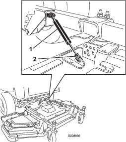
-
Remove the hairpin cotter and clevis pin securing the height-of-cut chains to the rear of the cutting unit (Figure 134).
-
Start the engine, slowly raise the front cutting unit, shut off the engine, and remove the ignition key.
-
Wedge a block of wood between the rear of the deck and the machine (Figure 135).
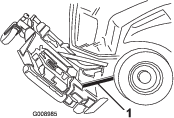
Pivoting (Tilting) the Front Cutting-Unit Down
-
With the help of another person holding the front of the cutting unit, remove the block of wood.
-
Sit on the seat, start the engine, and lower the cutting unit until it is slightly off the floor.
-
Secure the height-of-cut chains to the rear of the cutting unit.
-
Connect the damper assembly and secure it with the retainer clip.
Adjusting the Cutting-Unit Pitch
Measuring the Cutting-Unit Pitch
The mower-deck pitch is the difference between the height of cut from the front tip of the blade to the back tip. Set a blade pitch of 6.3 to 9.7 mm (0.25 to 0.38 inch); i.e., the back tip of the blade should be 7.5 mm (0.3 inch) higher than the front tip.
-
Park the machine on a level surface, engage the parking brake, lower the cutting deck, shut off the engine, and remove the key.
-
Set the cutting unit to the desired height of cut.
-
Ensure that the winglets are level to the front deck and the front deck is level side to side.
Adjusting the Front Cutting-Unit Pitch
-
Rotate each blade so that they point straight forward (Figure 136).
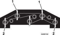
-
Using a short ruler, measure from the floor to the front tip of the front blade and record this dimension.
-
Measure from the floor to the back tip of the winglet blade and record this dimension.
-
Subtract the front dimension from the rear dimension to calculate the pitch of each blade.
-
Loosen the jam nuts on the top or bottom of the height-of-cut chain U-bolt (Figure 137).
Note: Loosen or tighten the height-of-cut chain nuts equally, so that the deck remains level from side to side.
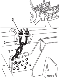
-
Adjust the other set of nuts to raise or lower the rear of the cutting unit and attain the correct mower-deck pitch based on the average pitch of each blade.
-
Tighten the jam nuts.
Adjusting the Wing Cutting-Unit Pitch
-
Remove the tensioning cap from the caster-spindle shaft and slide the spindle out of the caster arm (Figure 138).
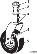
-
Position the shims, as required, to raise or lower the caster wheel until the cutting unit has the correct pitch.
-
Install the tensioning cap.
Servicing the Caster-Arm Bushings
The caster arms have bushings pressed into the top and bottom of the tube, and after many hours of operation, the bushings wear. To check the bushings, move the caster fork back and forth and from side to side. If the caster spindle is loose inside the bushings, the bushings are worn; replace them.
Remove the tensioning cap and caster fork (Figure 138).
Note: Record the position of the washers and spacers before you remove them so that you do not need to adjust the deck pitch.
Servicing the Caster Wheels and Bearings
| Maintenance Service Interval | Maintenance Procedure |
|---|---|
| Every 500 hours |
|
-
Remove the locknut from the bolt holding the caster-wheel assembly between the caster fork or the caster-pivot arm (Figure 139).
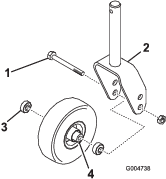
-
Grasp the caster wheel and slide the bolt out of the fork or pivot arm (Figure 139).
-
Remove the bearing from the wheel hub and allow the bearing spacer to fall out (Figure 139).
-
Remove the bearing from the opposite side of the wheel hub (Figure 139).
-
Check the bearings, spacer, and inside of the wheel hub for wear.
Note: Replace any damaged parts.
-
To assemble the caster wheel, push the bearing into the wheel hub.
Note: When installing the bearings, press on the outer race of the bearing.
-
Slide the bearing spacer into the wheel hub and push the other bearing into the open end of the wheel hub to captivate the bearing spacer inside the wheel hub.
-
Install the caster-wheel assembly between the caster fork and secure it in place with the bolt and locknut.
Blade Maintenance
Blade Safety
-
Inspect the blade periodically for wear or damage.
-
Use care when checking the blades. Wrap the blades or wear gloves, and use caution when servicing the blades. Only replace or sharpen the blades; never straighten or weld them.
-
On multi-bladed machines, take care as rotating one blade can cause other blades to rotate.
Checking for a Bent Blade
After striking a foreign object, inspect the machine for damage and make repairs before restarting and operating the equipment. Torque all the spindle-pulley nuts to 176 to 203 N·m (130 to 150 ft-lb).
-
Raise the cutting unit.
-
Perform the pre-maintenance procedure; refer to Pre-Maintenance Procedures.
-
Block the cutting unit to prevent it from accidentally falling.
-
Rotate the blade until the ends face forward and backward, and measure from the inside of the cutting unit to the cutting edge at the front of the blade (Figure 140).
Note: Record this dimension.

-
Rotate the opposite end of the blade forward and measure between the cutting unit and cutting edge of the blade at the same position as in step 4.
Note: The difference between the dimensions obtained in steps 4 and 5 must not exceed 3 mm (1/8 inch). If the dimension exceeds 3 mm (1/8 inch), the blade is bent and must be replaced; refer to Removing and Installing the Cutting-Unit Blade(s).
Removing and Installing the Cutting-Unit Blade(s)
Replace the blade if it hits a solid object, is out of balance, or is bent. Always use genuine Toro replacement blades to ensure safety and optimum performance.
-
Park the machine on a level surface, raise the cutting unit to the transport position, engage the parking brake, shut off the engine, and remove the key.
Note: Block the cutting unit to prevent it from accidentally falling.
-
Grasp the end of the blade using a rag or thickly-padded glove.
-
Remove the blade bolt, anti-scalp cup, and blade from the spindle shaft (Figure 141).
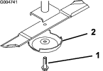
-
Install the blade, anti-scalp cup, and blade bolt and tighten the blade bolt to 115 to 149 N∙m (85 to 110 ft-lb).
Important: The curved part of the blade must be pointing toward the inside of the cutting unit to ensure proper cutting.
Note: After striking a foreign object, torque all spindle-pulley nuts to 115 to 149 N∙m (85 to 110 ft-lb).
Inspecting and Sharpening a Blade
| Maintenance Service Interval | Maintenance Procedure |
|---|---|
| After the first 10 hours |
|
| Before each use or daily |
|
| Every 50 hours |
|
Both cutting edges and the sail, which is the turned-up portion opposite of the cutting edge, contribute to a good quality of cut. The sail lifts the grass up straight, thereby producing an even cut. However, the sail gradually wears down during operation, degrading the quality of cut, although the cutting edges remain sharp. The cutting edge of the blade must be sharp so that the grass is cut, not torn. A cutting edge is dull when the tips of the grass appear brown and shredded. Sharpen the cutting edges to correct this condition.
-
Position the machine on a level surface, raise the cutting unit, engage the parking brake, put the traction pedal in NEUTRAL, ensure that the PTO switch is in the OFF position, shut off the engine, and remove the key.
-
Examine the cutting ends of the blade carefully (especially where the flat and curved parts of the blade meet) as shown in Figure 142.
Note: Since sand and abrasive material can wear away the metal that connects the flat and curved parts of the blade, check the blade before using the mower. If you notice wear, replace the blade (Figure 142).
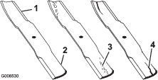
-
Examine the cutting edges of all of the blades.
-
Sharpen the cutting edges if they are dull or nicked (Figure 143).
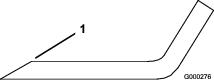
Note: Sharpen only the top of the cutting edge and maintain the original cutting angle to ensure the sharpness.
Note: The blade will remain balanced if the same amount of metal is removed from both cutting edges.
Note: Remove the blades and sharpen them on a grinder. After sharpening the cutting edges, install the blade with the anti-scalp cup and blade bolt; refer to Removing and Installing the Cutting-Unit Blade(s).
Correcting a Cutting-Unit Mismatch
When there is mismatch between the blades on a single cutting unit, the grass appears streaked when it is cut. You can correct this problem by ensuring that the blades are straight.
-
Using a 1 m (3 ft) long carpenter’s level, find a level surface on the shop floor.
-
Raise the height-of-cut to the highest position; refer to Adjusting the Height of Cut.
-
Lower the cutting unit onto a flat surface and remove the covers from the top of the cutting unit.
-
Rotate the blades until the ends face forward and backward.
-
Measure from the floor to the front tip of the cutting edge. Record this condition.
-
Rotate the same blade so that the opposite end is forward and measure it again.
Note: The difference between the dimensions must not exceed 3 mm (1/8 inch). If the dimension exceeds 3 mm (1/8 inch), replace the blade, as it is bent. Measure all the blades.
-
Ensure that the deck is level from side to side and adjust as required.
-
Install the belt covers.
Cab Maintenance
Cleaning the Cab
Important: Use care around the cab seals and lights (Figure 144). If you are using a pressure washer, keep the washer wand at least 0.6 m (2 ft) away from the machine. Do not use the pressure washer directly on the cab seals and lights or under the rear overhang.
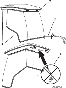
Cleaning the Cab Air Filters
| Maintenance Service Interval | Maintenance Procedure |
|---|---|
| Every 250 hours |
|
-
Remove the screws and grates from both the in-cab and rear cab air filters (Figure 145 and Figure 146).
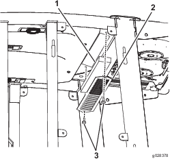
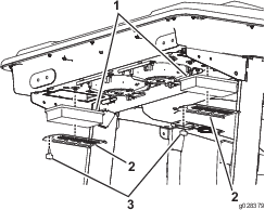
-
Clean the filters by blowing clean, oil-free, compressed air through them.
Important: If either filter has a hole, tear, or other damage, replace the filter.
-
Install the filters and the grate with the thumbscrews.
Cleaning the Cab Pre-Filter
The cab pre-filter prevents large debris, such as grass and leaves, from entering the cab filters.
-
Rotate the screen cover down.
-
Clean the filter with water.
Important: Do not use a pressure washer.
Note: If the filter has a hole, tear, or other damage, replace the filter.
-
Allow the pre-filter to dry before installing it into the machine.
-
Rotate the filter screen around the tabs until the latch locks into the latch-mount assembly (Figure 147).
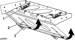
Cleaning the Air-Conditioning Assembly
| Maintenance Service Interval | Maintenance Procedure |
|---|---|
| Every 250 hours |
|
-
Disconnect the wire for each fan.
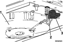
-
Remove the 2 knobs and remove the fan assembly.
-
Open the 4 latches on the air-conditioning assembly and remove the screen.
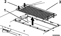
-
Remove the air filters (see Figure 146).
-
Clean the air-conditioning assembly.
-
Install the air filters, screen, and fan assembly (Figure 146, Figure 148, and Figure 149).
-
Connect the wire for each fan (Figure 148).
Storage
Storage Safety
-
Shut off the engine, remove the key, and wait for all movement to stop before you leave the operator’s position. Allow the machine to cool before adjusting, servicing, cleaning, or storing it.
-
Do not store the machine or fuel container where there is an open flame, spark, or pilot light, such as on a water heater or other appliance.
Preparing the Machine for Storage
Important: Do not use brackish or reclaimed water to clean the machine.
Preparing the Traction Unit
-
Thoroughly clean the traction unit, cutting units, and engine.
-
Check the tire pressure. Inflate all traction unit tires to 83 to 103 kPa (12 to 15 psi).
-
Check all fasteners for looseness and tighten them as necessary.
-
Grease all grease fittings and pivot points. Wipe up any excess lubricant.
-
Lightly sand and use touch-up paint on painted areas that are scratched, chipped, or rusted. Repair any dents in the metal body.
-
Service the battery and cables as follows:
-
Remove the battery terminals from the battery posts.
Note: Always disconnect the negative terminal first and the positive last. Always connect the positive terminal first and the negative last.
-
Clean the battery, terminals, and posts with a wire brush and baking soda solution.
-
Coat the cable terminals and battery posts with Grafo 112X skin-over grease (Part Number 505-47) or petroleum jelly to prevent corrosion.
-
Slowly recharge the battery every 60 days for 24 hours to prevent lead sulfation of the battery.
-
Preparing the Engine
-
Drain the engine oil from the oil pan and replace the drain plug.
-
Remove and discard the oil filter. Install a new oil filter.
-
Refill the oil pan with designated quantity of motor oil.
-
Turn the key in the switch to the ON position, start the engine, and run it at idle speed for approximately 2 minutes.
-
Turn the key in the switch to the OFF position.
-
Thoroughly drain all fuel from the fuel tank, lines, and the fuel filter/water separator assembly.
-
Flush the fuel tank with fresh, clean diesel fuel.
-
Secure all fuel-system fittings.
-
Thoroughly clean and service the air-cleaner assembly.
-
Seal the air-cleaner inlet and the exhaust outlet with weatherproof tape.
-
Check the antifreeze protection and add as needed for expected minimum temperature in your area.