Installation
Preparing the Machine
-
Park the machine on a level surface.
-
Engage the parking brake.
-
Lower the cutting unit.
-
Shut off the engine and remove the key.
-
Raise the rear of the machine and support it with jack stands. Refer to Operator’s Manual for the correct procedure.
-
Unlatch the hood and rotate it to the service position.
-
Remove the rear wheels.
Installing the Hose Guides to the Cooler-Shroud Brackets
Parts needed for this procedure:
| Right cooler-shroud bracket | 1 |
| Left cooler-shroud bracket | 1 |
| Flange nut (5/16 inch) | 4 |
| Hose guide | 2 |
| Flat washer (5/16 inch) | 4 |
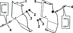
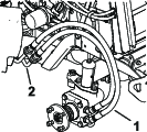
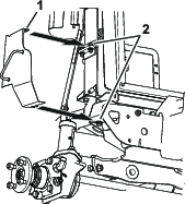
Install the hose guides to the left and right cooler-shroud brackets with 2 flat washers (5/16 inch) and 2 flange nuts (5/16 inch); refer to Figure 1.
Installing the Right Side Hoses
Parts needed for this procedure:
| Straight fitting | 1 |
| 90º elbow fitting | 1 |
| Hose with straight fittings | 1 |
| Hose with 90º elbow | 1 |
| Right cooler-shroud bracket assembly | 1 |
| Cap | 2 |
| Nylon locknut (3/8 inch) | 1 |
| Bolt (3/8 x 3 inches) | 1 |
| Flat washer (3/8 inch) | 1 |
Note: Install 1 side at a time.
-
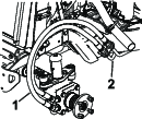
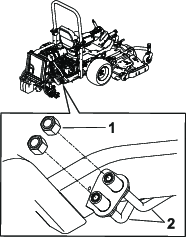
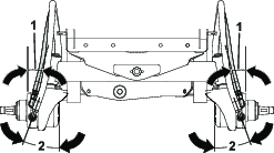
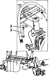
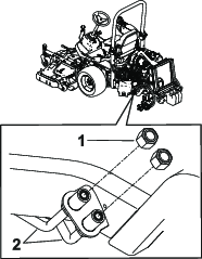
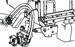
Remove the existing hydraulic hoses from the hydraulic lines in front of the wheel and immediately install the caps to the hydraulic lines (Figure 2 and Figure 3).
-
Remove the existing hose fittings from the wheel motor.
-
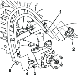
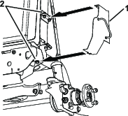
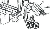
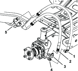
Install the new straight fitting and the 90º elbow fitting to the wheel motor (Figure 4).
-
Adjust the 90º elbow fitting to a 15º angle as shown in Figure 5.
-
Torque the wheel motor fittings to 142 N∙m (105 ft-lb).
-
Install the hose with straight fittings onto the 90º elbow fitting (Figure 4).
-
Install the hose with the 90º elbow to the straight fitting (Figure 4).
-
Adjust the 90º hose elbow to a 20º angle as shown in Figure 5.
-
Torque the hoses onto the fittings with 57 N∙m (42 ft-lb).
Note: Ensure the angles are maintained as shown in Figure 5.
-
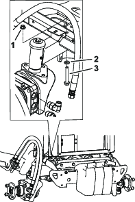
Remove the existing nut and bolt under the radiator that secures the bumper bracket (Figure 6).
-
Replace the existing nut and bolt with a bolt (3/8 x 3 inches), flat washer (3/8 inch), and flange nut (3/8 inch) to the frame. Do not tighten the bolt until the cooler-shroud bracket is installed.
-
Loosen the bolts on the side of the radiator (Figure 7).
-
Slide the cooler-shroud bracket under the bolt heads on the radiator and bumper bracket (Figure 7).
-
Push the cooler-shroud bracket all the way in and tighten the bolts.
-
Route the hoses through the hose guide (Figure 8).
-
Remove one cap at a time and install the correct hose to the hydraulic line as shown in Figure 4.
Note: Use a backing wrench to prevent the hoses from twisting.
-
Remove the remaining cap and install the hose to the hydraulic line (Figure 4).
-
Torque the hoses to the hydraulic lines with 85 N∙m (63 ft-lb).
Note: Ensure the hoses are aligned above and below each other and not to the side.
-
Install the rear wheel and ensure there is a 1.6 to 4.8 mm (1/16 to 3/16 inch ) clearance between the hoses and the tire sidewall.
-
Adjust the hose with the 90º elbow or 90° fitting if the clearance is not correct.
-
Torque the wheel-lug nuts; refer to the Operator’s Manual for the correct procedure.
Installing the Left Side Hoses
Parts needed for this procedure:
| Straight fitting | 1 |
| 90º elbow fitting | 1 |
| Hose with straight fittings | 1 |
| Hose with 90º elbow | 1 |
| Left cooler-shroud bracket assembly | 1 |
| Hose guide | 1 |
| Cap | 2 |
| Nylon locknut (3/8 inch) | 1 |
| Bolt (3/8 x 3 inches) | 1 |
| Flat washer (3/8 inch) | 1 |
-
Remove the existing hydraulic hoses from the hydraulic lines in front of the wheel and immediately install the caps to the hydraulic lines (Figure 9 and Figure 10).
-
Remove the existing hose fittings from the wheel motor.
-
Install the new straight fitting and the 90º elbow fitting to the wheel motor (Figure 11).
-
Adjust the 90º elbow fitting to a 15º angle as shown in Figure 12.
-
Torque the wheel motor fittings to 142 N∙m (105 ft-lb).
-
Install the hose with straight fittings onto the 90º elbow fitting (Figure 11).
-
Install the hose with the 90º elbow to the straight fitting (Figure 11).
-
Adjust the 90º hose elbow to a 20º angle as shown in Figure 12.
-
Torque the hoses onto the fittings with 57 N∙m (42 ft-lb).
Note: Ensure the angles are maintained as shown in Figure 12.
-
Remove the existing nut and bolt under the radiator that secures the bumper bracket (Figure 13).
-
Replace the existing nut and bolt with a bolt (3/8 x 3 inches), flat washer (3/8 inch), and flange nut (3/8 inch) to the frame. Do not tighten the bolt until the cooler-shroud bracket is installed.
-
Loosen the bolts on the side of the radiator (Figure 14).
-
Slide the left cooler-shroud bracket assembly under the bolt heads on the radiator and bumper bracket (Figure 14).
-
Push the cooler-shroud bracket all the way in and tighten the bolts.
-
Route the hoses through the hose guide (Figure 15).
-
Remove one cap at a time and install the correct hose to the hydraulic line as shown in Figure 11.
Note: Use a backing wrench to prevent the hoses from twisting.
-
Remove the remaining cap and install the hose to the hydraulic line (Figure 11).
-
Torque the hoses to the hydraulic lines with 85 N∙m (63 ft-lb).
Note: Ensure the hose are aligned above and below each other and not to the side.
-
Install the rear wheel and ensure there is a 1.6 to 4.8 mm (1/16 to 3/16 inch) clearance between the hoses and the tire sidewall.
-
Adjust the hose with the 90º elbow or 90° fitting if the clearance is not correct.
-
Torque the wheel-lug nuts; refer to the Operator’s Manual for the correct procedure.
-
Lower the hood and latch it.
-
Lower the rear of the machine.
-
Slowly drive the machine forward and reverse to purge the air out of the traction system.
-
Check the fitting connections and hoses for any leaks.
-
Check the hydraulic fluid level; refer to the Operator’s Manual for the correct procedure.