
 , which means
Caution, Warning, or Danger—personal safety instruction. Failure
to comply with these instructions may result in personal injury or
death.
, which means
Caution, Warning, or Danger—personal safety instruction. Failure
to comply with these instructions may result in personal injury or
death.


Maintenance
Warning
Failure to properly maintain the machine could result in premature failure of machine systems, causing possible harm to you or bystanders.
Keep the machine well maintained and in good working order as indicated in these instructions.
Note: Determine the left and right sides of the machine from the normal operating position.
Important: Do not tip the machine at an angle greater than 25°. Tipping the machine beyond 25° leads to oil leaking into the combustion chamber and/or fuel leaking out of the fuel-tank cap.
Important: Refer to your engine owner’s manual for additional maintenance procedures.
Maintenance Safety
-
Before you leave the operator’s position, do the following:
-
Park the machine on a level surface.
-
Move the throttle to the low-idle position.
-
Disengage the cutting unit(s).
-
Ensure that the traction is in neutral.
-
Engage the parking brake.
-
Shut off the machine and remove the key (if equipped).
-
Wait for all movement to stop.
-
-
Allow machine components to cool before performing maintenance.
-
If possible, do not perform maintenance while the machine is running. Keep away from moving parts.
-
If the engine must be running to perform a maintenance adjustment, keep your hands, feet, clothing, and any parts of the body away from the cutting unit, attachments, and any moving parts. Keep bystanders away.
-
Clean grass and debris from the cutting unit, drive, muffler, cooling screen, and the engine to help prevent fires. Clean up oil or fuel spills.
-
Keep all parts in good working condition. Replace all worn, damaged, or missing parts and decals. Keep all hardware tight to ensure that the machine is in safe working condition.
-
Check the grass catcher components frequently and replace them when necessary.
-
To ensure safe, optimal performance of the machine, use only genuine Toro replacement parts. Replacement parts made by other manufacturers could be dangerous, and such use could void the product warranty.
-
If major repairs are ever needed or if assistance is desired, contact an authorized Toro distributor.
Recommended Maintenance Schedule(s)
| Maintenance Service Interval | Maintenance Procedure |
|---|---|
| After the first 20 hours |
|
| Before each use or daily |
|
| Every 50 hours |
|
| Every 100 hours |
|
| Every 300 hours |
|
Pre-Maintenance Procedures
Preparing the Machine for Maintenance
Warning
While you are maintaining or adjusting the machine, someone could start the engine. Accidentally starting the engine could seriously injure you or other bystanders.
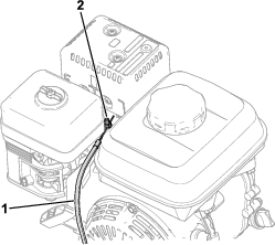
Release the clutch bail, engage the parking brake, and pull the wire off the spark plug before you do any maintenance. Also push the wire aside so it does not accidentally contact the spark plug.
Perform the following before servicing, cleaning, or making any adjustments to the machine.
-
Park the machine on a level surface.
-
Shut off the engine.
-
Engage the parking brake.
-
Wait for all moving parts to stop and allow the engine to cool before servicing, storing, or making repairs.
-
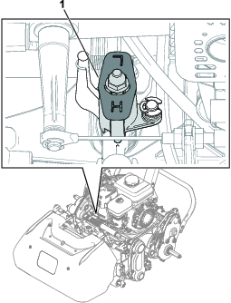
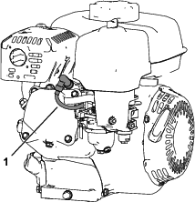
Disconnect the spark-plug wire (Figure 23).
Engine Maintenance
Engine Safety
-
Do not change the governor speed or overspeed the engine.
-
Run the engine dry or remove the fuel with a hand pump; never siphon the fuel. If you must drain the fuel tank, do it outdoors.
Servicing the Engine Oil
Fill the crankcase with approximately 0.56 L (19 fl oz) of the proper viscosity oil before starting. The engine uses a high-quality oil that has the American Petroleum Institute (API) service classification of SJ or higher. Select the proper oil viscosity (weight) based on the ambient temperature. Figure 24 illustrates the temperature/viscosity recommendations.
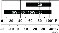
Note: Multi-grade oils (5W-20, 10W-30 and 10W-40) increase oil consumption. Check the engine-oil level more frequently when you use these oils.
Checking the Engine-Oil Level
| Maintenance Service Interval | Maintenance Procedure |
|---|---|
| Before each use or daily |
|
The ideal time to check the engine-oil level is when the engine is cool or before you have started the engine for the day. If you have already ran the engine, allow the oil to drain back down to the sump for at least 10 minutes before you check the engine-oil level.
-
Shut off the engine and wait for all moving parts to stop; refer to Shutting Off the Engine.
-
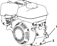
Position the machine so that the engine is level, and clean the area around the oil-fill tube (Figure 25).
-
Remove the dipstick by rotating it counterclockwise.
-
Remove the dipstick and wipe the end clean.
-
Insert the dipstick fully into the oil-fill tube, but do not thread it in.
-
Remove the dipstick and check the engine-oil level (Figure 26).
-
If the engine-oil level is incorrect, add or drain oil to correct the level; refer to Checking the Engine-Oil Level.
Changing the Engine Oil
| Maintenance Service Interval | Maintenance Procedure |
|---|---|
| After the first 20 hours |
|
| Every 100 hours |
|
Warning
Oil may be hot after the engine has been run, and contact with hot oil can cause severe personal injury.
Avoid contacting the hot engine oil when you drain it.
-
Shut off the engine and wait for all moving parts to stop; refer to Shutting Off the Engine.
-
Place a pan under the drain plug to catch the oil.
-
Remove the drain plug, washer, and dipstick (Figure 25).
-
Position the engine so that the oil drains from the engine.
-
When the oil has drained completely, move the engine to a level position and install the drain plug and a new washer.
Note: Dispose of the used oil at a certified recycling center.
-
Slowly pour oil into the oil-fill hole until the oil is at the correct level.
-
Ensure that the oil is at the correct level on the dipstick; refer to Checking the Engine-Oil Level.
-
Thread the dipstick into the oil-fill hole.
-
Wipe up any spilled oil.
-
Connect the wire to the spark plug.
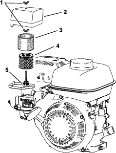
Servicing the Air Cleaner
| Maintenance Service Interval | Maintenance Procedure |
|---|---|
| Before each use or daily |
|
| Every 50 hours |
|
| Every 300 hours |
|
Important: Do not operate the engine without the air filter assembly; extreme engine damage will occur.
-
Shut off the engine and wait for all moving parts to stop; refer to Shutting Off the Engine.
-
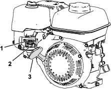
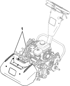
Remove the wingnut securing the air-cleaner cover (Figure 27).
-
Remove the air-cleaner cover.
Note: Ensure that no dirt or debris from the air-cleaner cover fall into the base.
-
Remove the foam and paper elements from the base.
-
Remove the foam element from the paper element.
-
Inspect the foam and paper elements; replace them if they are damaged or excessively dirty.
-
Clean the paper element by tapping it gently to remove the dirt.
Note: Do not try to brush dirt off the paper element; brushing forces the dirt into the fibers. Replace the element if tapping it fails to remove the dirt.
-
Clean the foam element in warm, soapy water or in a nonflammable solvent.
Note: Do not use gasoline to clean the foam element because it could create a risk of fire or explosion.
-
Rinse and dry the foam element thoroughly.
-
Wipe dirt from the base and the cover with a moist rag.
Note: Ensure that dirt and debris do not enter the air duct leading to the carburetor.
-
Install the air-cleaner elements and ensure that they are properly positioned. Install the lower wing nut.
-
Install the cover and install the upper wing nut to secure it.
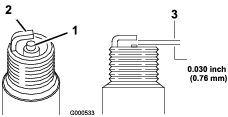
Servicing the Spark Plug
| Maintenance Service Interval | Maintenance Procedure |
|---|---|
| Every 100 hours |
|
| Every 300 hours |
|
Use an NGK BPR6ES spark plug or equivalent.
-
Shut off the engine and wait for all moving parts to stop; refer to Shutting Off the Engine.
-
Clean around the spark plug.
-
Remove the spark plug from the cylinder head.
Important: Replace a cracked, fouled, or dirty spark plug. Do not sand blast, scrape, or clean the electrodes because engine damage could result from grit entering the cylinder.
-
Set the gap on the plug to 0.7 to 0.8 mm (0.028 to 0.031 inch)
-
Carefully install the spark plug by hand (to avoid cross threading) until it is hand tight.
-
Tighten the spark plug an additional 1/2 turn if it is new; otherwise, tighten it an additional 1/8 to 1/4 turn.
Important: A loose spark plug can become very hot and can damage the engine; overtightening a spark plug may damage the threads in the cylinder head.
-
Connect the wire to the spark plug.
Controls System Maintenance
Adjusting the Traction Cable
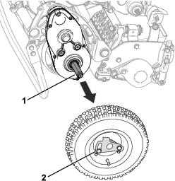
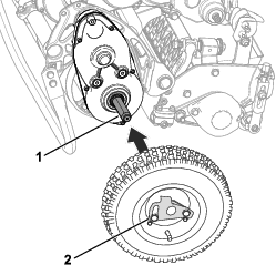
Adjust the traction cable to achieve a gap of 1.1 mm (0.045 inch) between the friction disc and the pressure plate.
Adjusting the Service/Parking Brake
Adjust the service/parking brake if it slips during operation.
-
Disengage the parking brake.
-
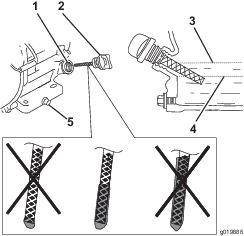
Measure the free play at the end of the parking-brake handle (Figure 32).
The handle free play should be between 12.7 to 25.4 mm (0.50 to 1 inch). If the free play is not within this amount, proceed to step 3 to adjust the brake cable.
-
Perform the following steps to adjust the brake-cable tension:
-
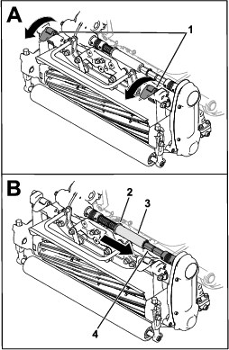
To increase the cable tension, loosen the front-cable jam nut and tighten the rear jam nut (Figure 33). Repeat step 2 and adjust the tension if necessary.
-
To decrease the cable tension, loosen the rear jam nut and tighten the front-cable jam nut (Figure 33). Repeat step 2 and adjust the tension if necessary.
-
Adjusting the Reel-Control Cable
To remove slack from the reel-control cable, perform the following steps:
-
Move the reel-speed-control knob to the high-reel-speed position; refer to Adjusting the Reel Speed.
-
Loosen the rear jam nut and tighten the front jam nut (Figure 34).
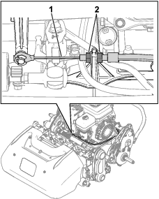
Adjusting the Throttle Cable
To adjust the low- and high-idle engine speed, adjust the cable conduit and the throttle-control stop; refer to Adjusting the Low-Idle Engine Speed and Adjusting the High-Idle Engine Speed.
Adjusting the Low-Idle Engine Speed
Note: Use a tachometer to observe the engine speed.
-
Park the machine on a level surface and engage the parking brake.
Note: Ensure that the engine is at a normal operating temperature before you adjust the throttle cable.
-
Start the engine and use the throttle control to decrease the engine speed to low idle.
-
Observe the low-idle engine speed on your tachometer.
The ideal range for low idle is 1,800 to 2,000 rpm.
-
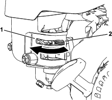
Loosen the screw on the cable-conduit clamp (Figure 35).
-
Move the cable conduit until you observe 1,900 rpm on the tachometer.
-
Tighten the screw on the cable-conduit clamp.
Adjusting the High-Idle Engine Speed
Note: Use a tachometer to observe the engine speed.
-
Park the machine on a level surface and engage the parking brake.
Note: Ensure that the engine is at a normal operating temperature before you adjust the throttle cable.
-
Start the engine and use the throttle control to increase the engine speed to high idle.
-
Observe the high-idle engine speed on your tachometer.
The ideal range for high idle (for use in non-CE-compliant countries) is 3,350 to 3,550 rpm. If the tachometer shows a speed below 3,350 or above 3,550 rpm, perform steps 4 through 6 until a speed between 3,350 to 3,550 rpm is attained.
If you use the machine in a country that complies to CE standards, adjust the high idle speed to the following specifications:
-
Flex 1018 machines: 3,000 rpm
-
Flex 1021 machines: 3,150 rpm
-
-
Shut off the engine.
-
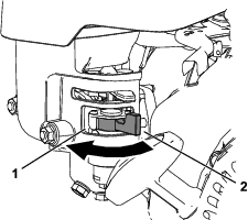
Adjust the throttle-control stop per the high-idle reading on your tachometer.
-
To increase the high-idle-speed threshold, move the throttle-control stop up.
-
To decrease the high-idle-speed threshold, move the throttle-control stop down.
-
-
Start the engine and observe the new high-idle reading.
If the tachometer shows the appropriate speed as detailed in step 3, the adjustment is completed.
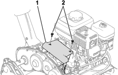
Tightening the Handle-Isolation Hardware
| Maintenance Service Interval | Maintenance Procedure |
|---|---|
| After the first 20 hours |
|
-
Position the machine on a level surface.
-
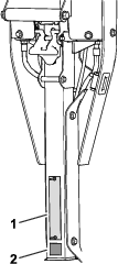
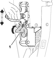
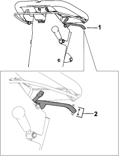
Loosen the bolt and nut as shown in Figure 37.
-
Push the handle as far forward as possible.
-
While supporting the handle, torque the bolt and nut that you loosened in step 2 to 68 to 75 N∙m (50 to 55 ft-lb).
Note: Have an assistant help you to support the handle or torque the hardware.
-
Release the handle.
Cutting Unit Maintenance
Blade Safety
Use care when checking the reel cutting-unit. Wear gloves and use caution when servicing the reel.
A worn or damaged blade or bedknife can break, and a piece could be thrown toward you or bystanders, resulting in serious personal injury or death.
-
Inspect the blades and bedknives periodically for excessive wear or damage.
-
Use care when checking the blades. Wear gloves and use caution when servicing them. Only replace or backlap the blades and bedknives; never straighten or weld them.
Installing the Cutting Unit
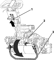
-
Move the kickstand to the CUTTING-UNIT-SERVICE position; refer to Kickstand.
-
Align the cutting unit to the frame.
-
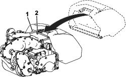
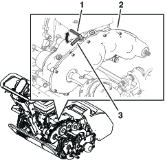
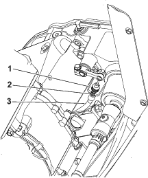
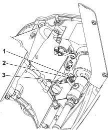
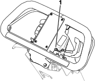
Move the suspension latches down to secure the cutting unit to the machine (Figure 38).
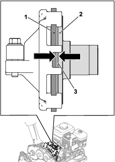
-
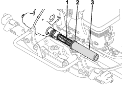
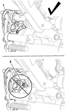
Move the collar out of the transmission-coupler-shaft groove and insert the hex tube into the cutting-unit coupler shaft (Figure 38).
-
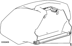
Install the grass basket.
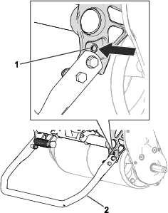
Removing the Cutting Unit
Note: The hex tube disengages if you engage the reel drive when the cutting unit is removed.
-
Move the kickstand to the CUTTING-UNIT-SERVICE position; refer to Kickstand.
-
Remove the grass basket (if equipped).
-
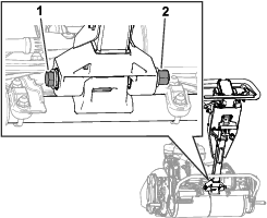
Move the collar (Figure 39) into the transmission-shaft groove.
Note: This releases tension from the spring.
-
Slide the hex tube off of the cutting-unit coupler shaft (Figure 39).
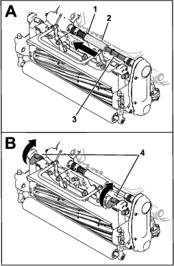
-
Move the suspension latches up to release the cutting unit from the machine (Figure 39).
-
Remove the cutting unit from the frame.
Backlapping the Cutting Unit
To backlap the cutting unit, use the Access Backlap Kit (Model 139-4342); refer to the operating instructions in the kit Installation Instructions. Contact your authorized Toro distributor to acquire this kit.