Note: Determine the left and right sides of the machine from the normal operating position.
Safety
Safety and Instructional Decals
 |
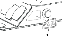
Safety decals and instructions are easily visible to the operator and are located near any area of potential danger. Replace any decal that is damaged or missing. |

Installation
Preparing the Machine
-
Park the machine on a level surface.
-
Lower the mower decks.
-
Engage the parking brake, shut off the engine, remove the key, and wait for all moving parts to stop.
Caution
If you leave the key in the switch, someone could accidently start the engine and seriously injure you or bystanders.
Remove the key from the ignition switch before you do any maintenance.
-
Open the hood.
-
Rotate the battery-disconnect switch to the OFF position (Figure 1).
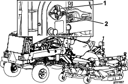
-
Allow the engine to cool down.
Installing the Momentary Switch
Parts needed for this procedure:
| Momentary switch | 1 |
| Washer (5/8 inch) | 1 |
| Jam nut (5/8 inch) | 1 |
| Decal | 1 |
| Wire Harness | 1 |
Preparing the Control Console
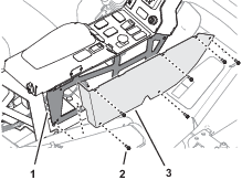
-
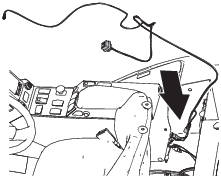
At the outboard side of the control console, remove the 5 flange-head capscrews that secure the right control-console cover (Figure 2).
-
Move the operator’s seat rearward.
-
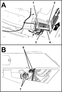
Measure 289 mm (11-3/8 inches) from the back of the of the console arm, and mark the surface of the left console panel (Figure 3).
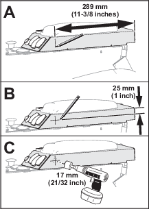
-
Measure 25 mm (1 inch) from the top of the of the console arm, and mark the surface of the left console panel (Figure 3).
-
At the intersection of the marks, center-punch the left console panel.
-
Drill a hole—17 mm (21/32 inch) at the center-punch mark (Figure 3).
Important: Use caution when drilling the console panel.
Assembling the Momentary Switch to the Control Console
-
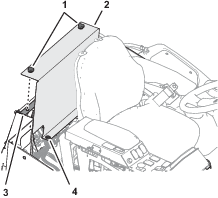
Assemble the momentary switch into the hole left console panel (Figure 4).
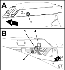
-
Inside the control console, secure the switch to the panel (Figure 4) with the washer (5/8 inch) and jam nut (5/8 inch).
-
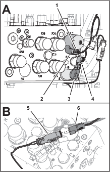
At the outboard side of the control console, adhere the decal to the left console panel as shown in Figure 5.
Connecting the Kit Wire Harness to the Momentary Switch
-
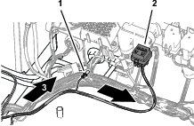
Position the kit wire harness behind the seat and control console as shown in Figure 6.
-
At the back of the control console, route the 2-wire branch (the branch with 2 single-receptacle terminals) of the kit wire harness along the platform wire harness and into the console (Figure 7).
-
Assemble the 2 single-receptacle terminals onto the spade terminals of the momentary switch (Figure 7).
Removing the Electrical Panel Cover
-
Move the operator’s seat fully forward.
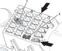
-
Loosen the knobs that secure the electrical-panel cover to the machine, and remove the cover (Figure 8).
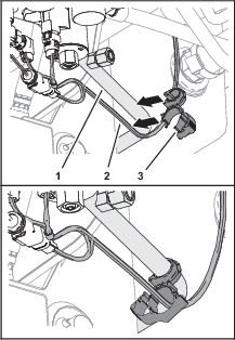
Installing the Kit Wire Harness at the Electrical Panel
Routing the Kit Wire Harness to the Electrical Panel
Route the branch of the wire kit harness with the spade connector and the 5-socket connector along the platform wire harness of the machine, and toward the fuse block (Figure 9).
Installing the Kit Wire Harness to the Fuse Block
-
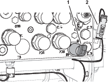
At the bottom of the fuse block, locate the wire attached to socket C5 of the block and remove the shrink-wrap insulator from the terminal receptacle (Figure 10).
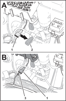
-
Plug the spade connector of the kit wire harness (Figure 10) into the terminal receptacle for the options power wire (fuse-block socket C5).
-
Insert the fuse (10 A) into fuse-block socket C5 (Figure 11).
Installing the Kit Wire Harness to the Traction Manifold
Parts needed for this procedure:
| Traction-control valve | 1 |
| Coil | 1 |
| Coil nut | 1 |
| MOC-LOC fastener | 1 |
| Cable tie | 1 |
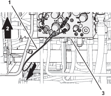
Routing the Kit Wire Harness to the Traction Manifold
Installing the Coil and Valve to the Traction Manifold
-
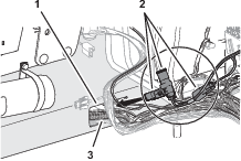
Remove the relief-valve cartridge from port of the traction manifold (Figure 15).
Note: Loosen the relief-valve cartridge using the hex flats of the valve body.
-
Install the traction-control valve into port of the traction manifold (Figure 15).
Important: Tighten the valve using the hex flats of the valve body.
-
Assemble the coil onto the traction-control valve, and secure the coil with the coil nut (Figure 15).
-
Torque the coil nut to 9.5 to 13.6 N∙m (84 to 120 in-lb).
Connecting the Kit Wire Harness to the Traction Manifold
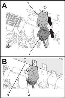
-
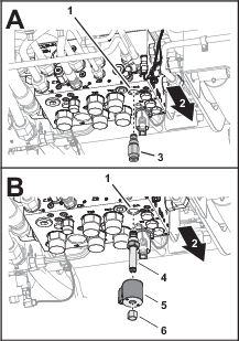
Remove the 2-socket connector of the machine wire harness labeled from the 2-pin connector of the solenoid valve in port of the traction manifold (Figure 16).
-
Plug the 90° 2-socket connector of the kit wire harness into the 2-pin connector of the solenoid valve in port of the traction manifold (Figure 17).
-
Plug the straight 2-socket connector of the kit wire harness into the 2-pin connector of the coil at port of the traction manifold (Figure 17).
-
Plug the 2-socket connector of the machine wire harness labeled into the 2-pin connector of the kit wire harness (Figure 17).
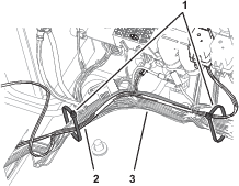
Securing the Kit Wire Harness to the Machine
-
At the bottom of the machine, clip the MOC-LOC fastener to the tube connecting port M7 of the traction manifold to the right, front traction motor, as shown in Figure 18.

-
Align the kit wire harness though the clamp side of the MOC-LOC fastener, and secure the clamp around the harness (Figure 18).
-
At the top of the machine, secure the kit wire harness to the platform wire harness with 2 cable ties (Figure 19)

Installing the Electrical-Panel and Control-Console Covers
-
Align the grommets at the bottom of the electrical-panel cover (Figure 20) with the 2 pins in the floor panel.
-
Align the threaded rods of the knobs attached to the cover with the cinch nuts of the electrical plate (Figure 20).
-
Assemble the cover to the plate and secure the panel with the knobs (Figure 20).
-
At the outboard side of the control console, align the holes in the right control-console cover with the holes in the console (Figure 21).
-
Assemble the cover to the control console (Figure 21) with the 5 flange-head capscrews that you removed in Preparing the Control Console.
Finishing the Kit Installation
Connecting the Battery
-
Rotate the battery-disconnect switch to the ON position (Figure 22).
-
Close the hood and secure it with the 2 hood latches.
Testing the Traction System
-
Start the engine and disengage the parking brake.
-
Press the high—low range-speed switch to the L (low range) position (Figure 23)
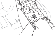
-
Press and hold the momentary switch (Figure 23).
-
To feel the 4-wheel drive is more aggressive, slowly drive the machine in a full turn.
Note: You should feel increased powertrain torque and it is easily felt on a paved surface.
-
While driving the machine in a turn, release the momentary switch to confirm that the 4-wheel drive returns to it’s normal mode.
-
Stop the machine, engage the parking brake, shut off the engine, remove the key, and wait for all moving parts to stop.
Operation
Operating the Traction System
Note: The 4-wheel drive momentary switch engages a more aggressive 4-wheel drive mode while the switch is pressed.
-
Stop the machine.
-
Press the high—low range-speed switch to the L (low range) position (Figure 24).
Important: Do not use the 4-wheel drive switch while the traction system is in high range.
Note: Only use the 4-wheel drive switch when necessary to avoid premature wear on the traction system.
-
Press and hold the 4-wheel drive switch to engage a more aggressive 4-wheel drive response (Figure 24).
-
Drive the machine while pressing the 4-wheel drive switch.
-
Release the 4-wheel drive switch to drive the machine in the normal 4-wheel drive mode.