Safety
Safety and Instructional Decals
 |
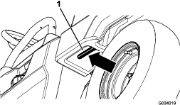
Safety decals and instructions are easily visible to the operator and are located near any area of potential damage. Replace any decal that is damaged or missing. |
Installation
Preparing the Machine
-
Park the machine on a level surface.
-
Engage the parking brake.
-
Shut off the machine and remove the key.

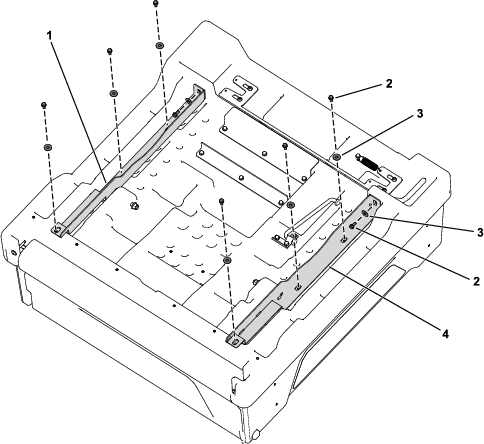
Installing the Cargo Bed Supports
Parts needed for this procedure:
| Right cargo bed support | 1 |
| Left cargo bed support | 1 |
| Flange-head bolt (5/16 x 3/4 inch) | 8 |
| Washer | 8 |
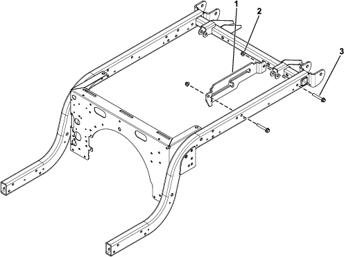
Installing the Prop Rod Bracket
Parts needed for this procedure:
| Prop rod bracket | 1 |
| Hex-head bolt (3/8 x 2-1/2 inches) | 2 |
| Locknut (3/8 inch) | 2 |
-
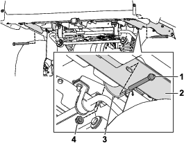
Secure the prop rod bracket to the machine frame using 2 hex-head bolts (3/8 x 2-1/2 inches) and 2 locknuts (3/8 inch) as shown in Figure 3.
-
Torque the 2 hex-head bolts (3/8 x 2-1/2 inches) to 41 N∙m (30 ft-lb).
Installing the Cargo Bed
Parts needed for this procedure:
| Bolt (1/2 x 4-1/2 inches) | 2 |
| Flange nut | 2 |
-
Park the machine on a level surface, engage the parking brake, shut off the machine, and remove the key.
-
Rotate the cargo bed so that the pivot-bracket assembly and prop rod are facing downward.
-
Using lifting equipment at the front and back of the cargo bed, raise the cargo bed and align it over the frame of the machine with the pivot-bracket assembly rearward (Figure 4).
-
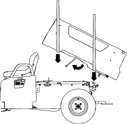
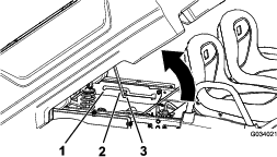
Adjust the height and position of the lifting equipment so that the short leg of the prop rod is aligned with the key hole at the end of the prop-rod slot in the left-frame channel or prop-rod bracket (Figure 5).
Note: You must angle the cargo bed with the lifting equipment in order to align the prop rod to the key hole.
-
Swing the prop rod forward and insert the short leg of the rod through the key hole (Figure 5).
-
Move the cargo bed and prop rod rearward until the pivot-bracket assembly is aligned over the rear-frame channel.
-
Carefully lower the cargo bed until the holes in the pivot brackets align with the mounting holes in the cargo bed supports (Figure 6).
-
Use 2 bolts (1/2 x 4-1/2 inches) and 2 flange nuts to secure the right and left cargo bed supports to the pivot brackets (Figure 6).
-
Torque the 2 flange nuts to 16 to 19 N∙m (140 to 170 in-lb).
Adjusting the Cargo-Bed Latches
If the cargo-bed latch is out of adjustment, the cargo bed vibrates up and down as you drive the machine. You can adjust the latch posts to make the latches hold the cargo bed securely to the chassis.
-
Verify that the cargo bed is latching.
Note: If the cargo bed does not latch, the bed-latch striker is likely too low. If the cargo bed latches, but vibrates up and down as you drive, the bed-latch striker is likely too high.
-
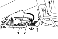
Pull on the lever on the left, inside of the cargo bed toward you and lift the cargo bed up (Figure 7).
-
Pull the prop rod into the dump position detent slot, securing the bed in a dumping position (Figure 8).
-
Loosen the 2 bolts on the bed-latch striker and move the striker up or down, depending on if the striker is too high or too low (Figure 9).
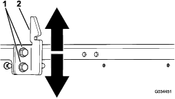
-
Tighten the 2 bolts on the bed-latch striker (Figure 9).
-
Verify that the adjustment is correct by latching the cargo bed several times.