Parts needed for this procedure:
| Console harness | 1 |
| Cap plug | 1 |
| Fuse mount plate | 1 |
| Clip nut (#10) | 1 |
| Flasher | 1 |
| Flange head screw (#10 x 3/8 inch) | 1 |
| Cable tie | 1 |
| Bracket mount | 2 |
| Clip nut (1/4 inch) | 8 |
| Switch mount | 1 |
| Multi-function switch | 1 |
| Switch clip (thick) | 1 |
| Switch clip (thin) | 1 |
| Switch plug | 3 |
| Rocker switch | 1 |
| Knob | 2 |
| Fuse cover | 1 |
| Bolt retainer | 2 |
| Carriage bolt (1/4 x 2 inches) | 4 |
| Flange locknuts | 4 |
| Cable ties | 2 |
| Push-in fastener | 2 |
| Flange-heads screw (1/4 x 3/4 inch) | 4 |
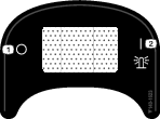
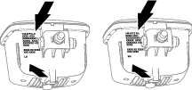
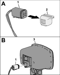
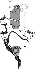
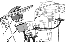
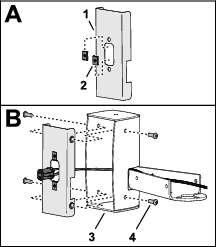
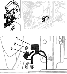
Installing the Console Harness Connector Plug
-
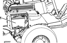
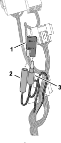
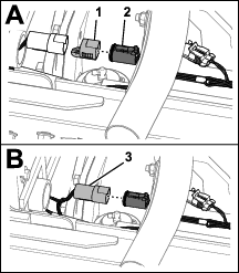
Disconnect the single-pin connector from the single-socket
connector labeled (Figure 18).
-
Plug the single-pin connector and the single-socket
connector into the cap plug (Figure 18).
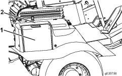
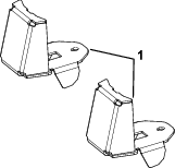
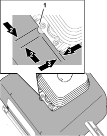
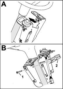
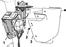
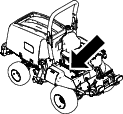
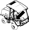
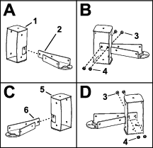
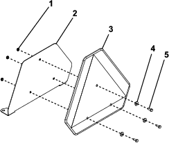
Preparing the Steering Cover and Routing the Control Harness
-
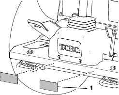
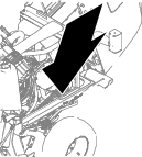
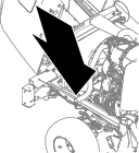
Remove the boot from the steering cover, and slide
the boot up (Figure 19).
-
Remove the 4 flange-head screws that secure the steering
cover to the cover mounts, and lift the cover (Figure 19).
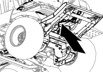
-
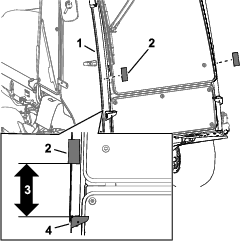
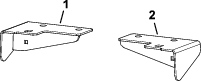
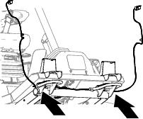
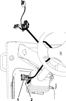
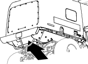
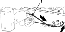
Grind a notch in the steering cover as show in Figure 20.
-
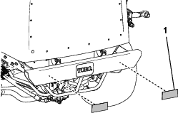
Align the 12-pin connector end of the control harness
through notch in the steering cover (Figure 21).
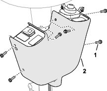
-
Assemble the steering cover to the cover mounts with
the 4 flange-head screws.
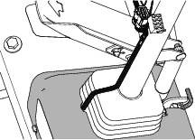
-
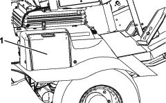
Pull the boot down and assemble the bottom of it into
the steering cover (Figure 22).
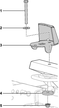
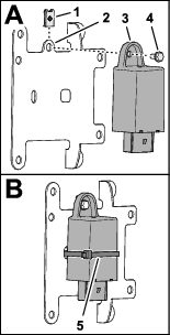
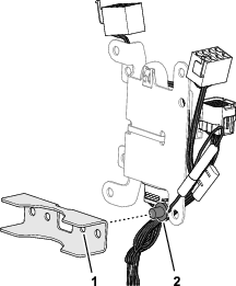
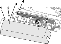
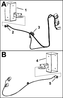
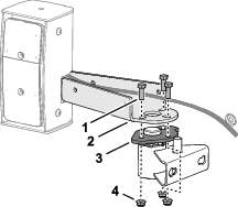
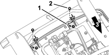
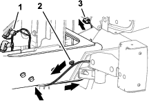
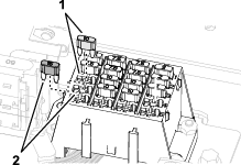
Assembling the Fuse Mount Plate
-
Assemble the clip nut (#10) onto the fuse mount plate
(Figure 23).
-
Assemble the flasher to the mount plate (Figure 23) with a
flange head screw (#10 x 3/8 inch).
-
Secure the flasher to the mount plate with a cable
tie (Figure 23).
-
Plug the 12-socket connector of the console harness
into the 12-pin connector of the flasher (Figure 24).
-
Insert push-in anchor of the console harness into
the 6.4 mm (1/4 inch) hole in the bracket mount (Figure 25).
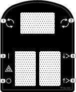
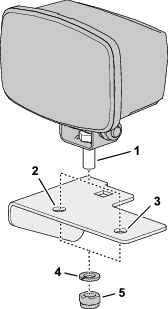
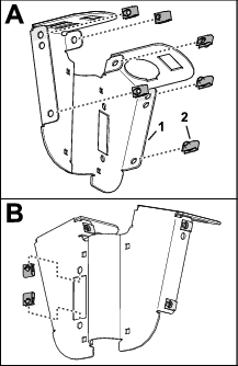
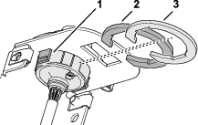
Assembling the Switch Mount
-
Assemble the 8 clip nuts (1/4 inch) to the switch
mount as shown in Figure 26.
-
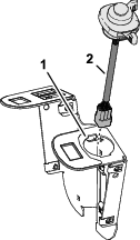
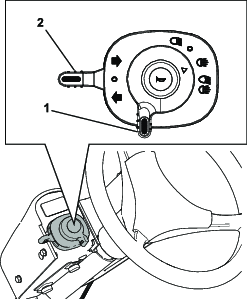
Insert the multi-function switch into the 100 mm (2
inch) hole in the switch mount as shown in Figure 27.
-
Secure the multi-function switch to the switch mount
with the thick and thin switch clips (Figure 28).
-
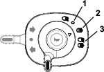
Insert the 3 switch plugs into the switch mount as
shown in Figure 29.
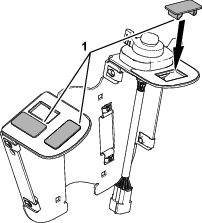
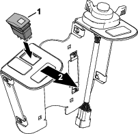
-
Align the rocker switch to the switch mount with the
lens of the light to the front of the switch plate (Figure 30).
-
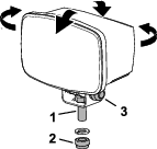
Assemble the 2 knobs into the fuse cover, and secure
the knobs with 2 bolt retainers (Figure 31).
-
Assemble the fuse cover to the switch plate, and tighten
the knobs (Figure 31).
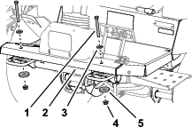
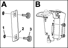
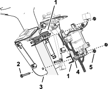
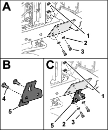
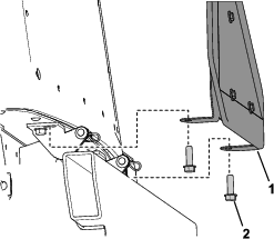
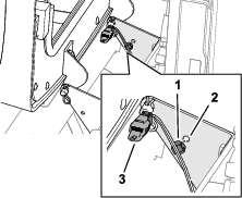
Installing the Switch Plate to the Steering Column
-
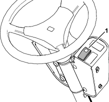
Align the switch plate to the rearward side or the
steering column (Figure 33).
-
At the upper 6.4 mm (1/4 inch) holes, assemble 2 carriage
bolts bolt (1/4 x 2 inches) through the switch plate and the other
bracket mount (Figure 32).
-
Assemble the fuse mount plate to the upper bracket
mount and carriage bolts (Figure 33) with 2 flange locknuts (1/4
inch).
-
At the lower 6.4 mm (1/4 inch) holes, assemble 2 carriage
bolts bolt (1/4 x 2 inches) through the switch plate, bracket mount,
and fuse mount plate (Figure 33) with 2 carriage bolts (1/4 x 2 inches) and 2 flange
locknuts (1/4 inch).
-
Align the switch plate to the operator’s seat,
and tighten the 4 flange locknuts.
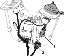
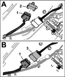
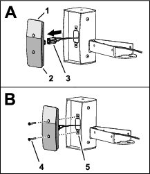
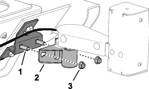
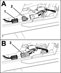
Connecting the Console Harness to the Switches
-
Plug the 8-socket connector of the control harness
labeled into the 8-pin connector of the rocker switch (Figure 34).
-
Plug the 9-pin connector of the multi-function switch
harness into the 9-socket connector of the console harness (Figure 35).
-
Secure the console harness to the steering column
with 2 cable ties.
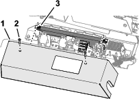
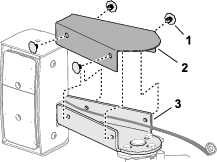
Installing the Control Cover
-
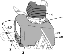
Align the holes in the control cover to the holes
in the switch mount (Figure 36).
-
Using the middle holes, secure the cover to the mount
with 2 push-in fasteners as shown in Figure 36.
-
Secure the cover to the mount with 4 flange-heads
screws (1/4 x 3/4) as shown in Figure 37.