Installation
Note: Retain all removed parts for later installation unless otherwise noted.
Preparing the Machine
-
Park the machine on a level surface.
-
Disengage the PTO and engage the parking brake.
-
Lower the cutting unit.
-
Shut off the engine and remove the key.
-
Wait for all moving parts to stop.
-
Allow the engine to cool completely.
Drilling the Hole for the Switch
-
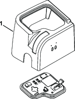
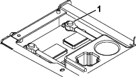
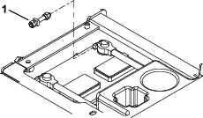
Remove the cover from the battery box (Figure 1).
Warning
Battery terminals or metal tools could short against metal machine components, causing sparks. Sparks can cause the battery gasses to explode, resulting in personal injury.
-
When disconnecting or connecting the battery, do not allow the battery terminals to touch any metal parts of the machine.
-
Do not allow metal tools to short between the battery terminals and metal parts of the machine.
Warning
Incorrect battery cable routing could damage the machine and cables causing sparks. Sparks can cause the battery gasses to explode, resulting in personal injury.
-
Always disconnect the negative (black) battery cable before disconnecting the positive (red) cable.
-
Always connect the positive (red) battery cable before connecting the negative (black) cable.
-
-
Disconnect the negative (-) battery cable from the battery (Figure 1).
-
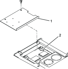
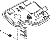
Remove the 2 screws securing the console shroud and remove the shroud (Figure 2).
-
Check your machine for an existing hole for the light switch in the control panel. If your machine has an existing hole, proceed to the step after the drilling information.
-
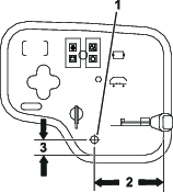
Using the dimensions shown in Figure 3, locate, mark, and drill a 13 mm (1/2 inch) diameter hole in the control panel.
Note: Install the control panel after you install the harness to the switch. Refer to Installing the Wire Harnesses.
Installing the Light Assemblies
Parts needed for this procedure:
| Light bracket | 2 |
| Bolt (5/16 x 1/2 inches) | 2 |
| Nut (5/16 inch) | 6 |
| Light assembly | 2 |
| Hex-head flange bolt (5/16 x 3/4 inches) | 4 |
-
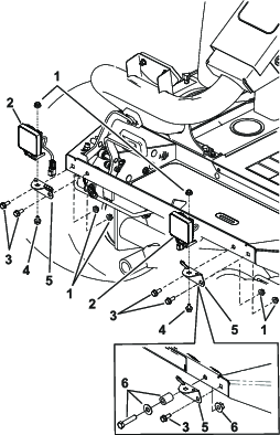
For a Reelmaster 3100 machine, mount the light brackets to the front of the footrest with 4 hex-head flange bolts (5/16 x 3/4 inches) and 4 locknuts (5/16 inch); refer to Figure 4.
-
For a Groundsmaster 3500 machine, mount the light brackets to the front of the footrest with 2 hex-head flange bolts (5/16 x 3/4 inches), 2 locknuts (5/16 inch), and the existing hardware and spacer; refer to Figure 4.
Note: The spacer and existing hardware is used for the mower deck latch on the Groundsmaster 3500 machine.
-
Mount the 2 lights to the brackets with 2 bolts (5/16 x 1/2 inch) and 2 locknuts (5/16 inch); refer to Figure 4.
Installing the Wire Harnesses
Parts needed for this procedure:
| Wire harness (black and blue light connectors) | 1 |
| Wire harness 15.2 cm (6 inch) | 1 |
| Switch assembly | 1 |
Use this procedure for traction units with the following serial number ranges.
-
Reelmaster 3100 with serial numbers 240000001 to present
-
Groundsmaster 3500 with serial numbers 240000001 to present
-
Groundsmaster 3505 with serial numbers 250000001 to present
-
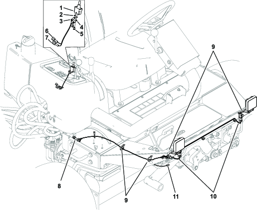
Connect the harness with the 2 black and blue wired connectors to the lights.
-
Route the single black wired ring terminal through the hole in the frame to the battery compartment.
Note: Do not connect to the battery at this point.
-
Connect the blue wired male terminal on the harness to the existing blue wired female terminal located under the operator platform at the top right corner (Figure 6).
-
Secure the harness with plastic ties.
-
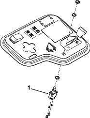
Mount the switch to control panel with the hex nuts and lock washer (Figure 5).
Note: The key way slot in the switch mounting threads indicates the OFF position.
-
Connect the 15.2 cm (6 inch) long harness with the blue and white terminals to the light switch as follows:
-
Connect the white wired male terminal on the harness to the white wired female terminal below the control panel on the main wire harness.
-
Connect the blue wired male terminal on the harness to the blue wired female terminal below the control panel on the main wire harness.
-
Install the 10 amp fuse into the open receptacle in the fuse block (Figure 7).
-
Install the control panel shroud.
-
Remove and discard the existing negative (-) battery cable clamp bolt (Figure 8).
-
Loosely install the new battery clamp bolt/ground stud (Figure 9).
-
Connect the black wired ring terminal to the ground stud.
-
Connect the negative (-) battery cable to the battery.
-
Install the battery box cover (Figure 1).
-
Switch the lights on.
-
Aim the lights as desired and tighten the mounting nuts.