
 , which means Caution, Warning,
or Danger—personal safety instruction. Failure to comply with
these instructions may result in personal injury or death.
, which means Caution, Warning,
or Danger—personal safety instruction. Failure to comply with
these instructions may result in personal injury or death.


Maintenance
Note: Determine the left and right sides of the machine from the normal operating position.
Caution
If you leave the key in the key switch, someone could accidently start the engine and seriously injure you or other bystanders.
Remove the key from the key switch and disconnect the wires from the spark plugs before you do any maintenance. Set the wires aside so that they do not accidentally contact the spark plugs.
Maintenance Safety
-
Park the machine on a level surface, disengage the grinder hydraulics, lower the grinder, engage the parking brake, shut off the engine, and remove the key. Wait for all movement to stop and allow the machine to cool before adjusting, servicing, cleaning, or storing it.
-
Clean up oil or fuel spills.
-
Do not allow untrained personnel to service the machine.
-
Use jack stands to support the components when required.
-
Carefully release pressure from components with stored energy.
-
Disconnect the battery before making any repairs.
-
Keep your hands and feet away from the moving parts. If possible, do not make adjustments with the engine running.
-
Keep all parts in good working condition and all hardware tightened. Replace all worn or damaged decals.
-
Do not tamper with the safety devices.
-
Use only genuine Toro replacement parts.
Recommended Maintenance Schedule(s)
| Maintenance Service Interval | Maintenance Procedure |
|---|---|
| After the first 50 hours |
|
| Before each use or daily |
|
| After each use |
|
| Every 25 hours |
|
| Every 100 hours |
|
| Every 150 hours |
|
| Every 200 hours |
|
| Every 250 hours |
|
| Every 300 hours |
|
| Every 400 hours |
|
| Every 500 hours |
|
| Every 600 hours |
|
| Every 1,500 hours |
|
| Yearly or before storage |
|
Important: Refer to your engine owner's manual for additional maintenance procedures.
Pre-Maintenance Procedures
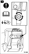
Important: The fasteners on the covers of this machine are designed to remain on the cover after removal. Loosen all fasteners on each cover a few turns so that the cover is loose but still attached, then go back and loosen them until the cover comes free. This prevents you from accidentally stripping the bolts free of the retainers.
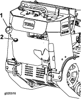
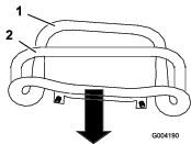
Removing the Front Cover
Important: The fasteners on the covers of this machine are designed to remain on the cover after removal. Loosen all fasteners on each cover a few turns so that the cover is loose but still attached, then go back and loosen them until the cover comes free. This prevents you from accidentally stripping the bolts free of the retainers.
-
Park the machine on a level surface, engage the parking brake, and lower the grinder.
-
Shut off the engine, remove the key, and allow the engine to cool.
Warning
If the machine has been running, both the cover and the muffler under the cover will be hot and can cause severe burns if you touch them.
Allow the machine to cool before removing the cover.
-
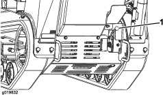
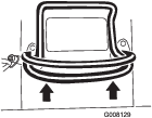
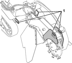
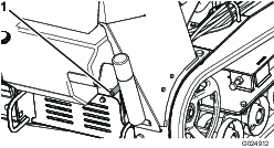
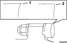
Remove the front bolt and loose then left bolt securing the front cover to the machine (Figure 24).
-
Slide the cover forward slightly and pull up to remove the cover (Figure 24).
-
To install the front cover, slide the front cover into place and secure it with the 2 bolts (Figure 24).
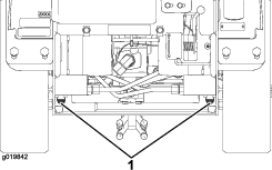
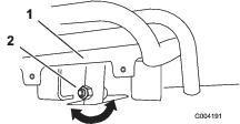
Removing the Bottom Shield
Important: The fasteners on the covers of this machine are designed to remain on the cover after removal. Loosen all fasteners on each cover a few turns so that the cover is loose but still attached, then go back and loosen them until the cover comes free. This prevents you from accidentally stripping the bolts free of the retainers.
-
Park the machine on a level surface, engage the parking brake (if applicable), and lower the grinder.
-
Shut off the engine and remove the key.
-
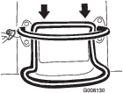
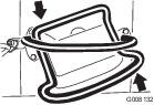
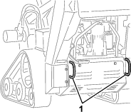
Loosen the 2 bolts securing the bottom shield sequentially until the shield is free (Figure 25).
-
Pull the shield back and out of the machine.
-
To install the shield before operating the machine, slide the bottom shield into the machine so that it rests on all 4 tabs and secure it with the 2 bolts you loosened previously (Figure 25).
Note: You may need to lift up on the bottom shield to ensure that it rests on the front tabs.
Lubrication
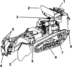
Greasing the Machine
| Maintenance Service Interval | Maintenance Procedure |
|---|---|
| Before each use or daily |
|
Grease Type: General-purpose grease
-
Park the machine on a level surface, engage the parking brake, and lower the grinder.
-
Shut off the engine and remove the key.
-
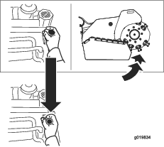
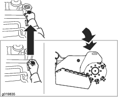
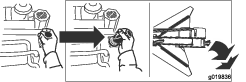
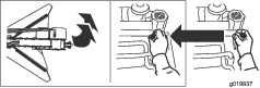
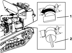
Clean the grease fittings with a rag.
-
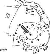
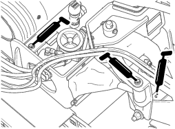
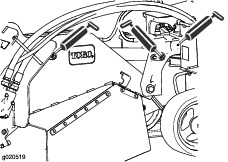
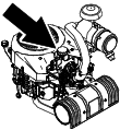
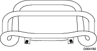
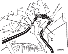
Connect a grease gun to each fitting (Figure 26 through Figure 28).
-
Pump grease into the fittings until grease begins to ooze out of the bearings (approximately 3 pumps).
-
Wipe up any excess grease.
Engine Maintenance
Engine Safety
-
Shut off the engine before checking the oil or adding oil to the crankcase.
-
Do not change the engine governor setting or overspeed the engine.
-
Keep your hands, feet, face, clothing, and other body parts away from the muffler and other hot surfaces.
Servicing the Air Cleaner
| Maintenance Service Interval | Maintenance Procedure |
|---|---|
| Every 150 hours |
|
| Every 250 hours |
|
| Every 300 hours |
|
| Every 600 hours |
|
Removing the Filters
-
Park the machine on a level surface, engage the parking brake (if applicable), and lower the grinder.
-
Shut off the engine and remove the key.
-
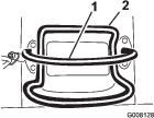
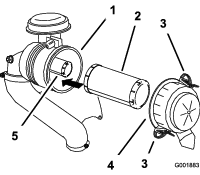
Release the latches on the air cleaner and pull the air-cleaner cover off the air-cleaner body (Figure 29).
-
Clean the inside of the air-cleaner cover with compressed air.
-
Gently slide the primary filter out of the air-cleaner body (Figure 29).
Note: Avoid knocking the filter into the side of the body.
-
Remove the safety filter only if you intend to replace it.
Important: Do not attempt to clean the safety filter. If the safety filter is dirty, then the primary filter is damaged. Replace both filters.
Servicing the Primary Filter
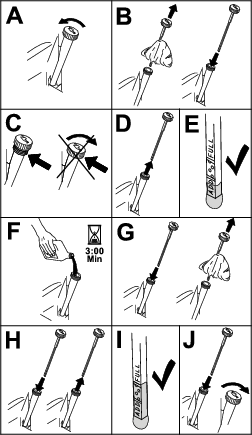
Inspect the primary filter for damage by looking into the filter while shining a bright light on the outside of the filter.
Note: Holes in the filter appear as bright spots. If the filter is dirty, bent, or damaged, replace it. Do not clean the primary filter.
Servicing the Safety Filter
Replace the safety filter; never clean it.
Important: Do not attempt to clean the safety filter. If the safety filter is dirty, then the primary filter is damaged. Replace both filters.
Installing the Filters
Important: To prevent engine damage, always operate the engine with both air filters and the cover installed.
-
If you are installing new filters, check each filter for shipping damage.
Note: Do not use a damaged filter.
-
If you are replacing the safety filter, carefully slide it into the filter body (Figure 29).
-
Carefully slide the primary filter over the safety filter (Figure 29).
Note: Ensure that the primary filter is fully seated by pushing on its outer rim while installing it.
Important: Do not press on the soft inside area of the filter.
-
Install the air-cleaner cover with the side indicated as up facing upward and secure the latches (Figure 29).
Servicing the Engine Oil
| Maintenance Service Interval | Maintenance Procedure |
|---|---|
| Before each use or daily |
|
| Every 100 hours |
|
| Every 200 hours |
|
Engine-Oil Specifications
Oil Type: Detergent oil (API service class SJ or higher)
Oil Capacity: 2.0 L (67 fl oz) without filter;
2.3 L (77 fl oz) with filter
Viscosity: See the table below.
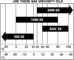
Note: Synthetic oils provide better starting in extreme cold below -23°C (-10°F).
Checking the Engine-Oil Level
-
Park the machine on a level surface, engage the parking brake (if applicable), and lower the grinder.
-
Shut off the engine and remove the key.
Changing the Engine Oil
Note: Dispose of the used oil at a recycling center.
-
Start the engine and let it run 5 minutes.
Note: This warms the oil so that it drains better.
-
Park the machine so that the rear is slightly lower than the front to ensure the oil drains completely.
-
Engage the parking brake and lower the grinder.
-
Shut off the engine and remove the key.
-
Place a pan below the drain hose. Rotate the oil drain valve to allow oil to drain (Figure 32 and Figure 33).
-
When oil has drained completely, close the drain valve.
-
Dispose of the used oil at a recycling center
-
Slowly pour approximately 80% of the specified oil into the filler tube and slowly add the additional oil to bring it to the Full mark (Figure 34).
-
Start the engine and drive to a flat area. Check the oil level again.
Changing the Engine-Oil Filter
-
Drain the oil from the engine; refer to Changing the Engine-Oil Filter.
-
Change the engine-oil filter (Figure 35).
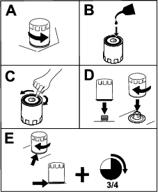
Note: Ensure that the oil-filter gasket touches the engine, and then turn the oil filter an extra 3/4 turn.
-
Fill the crankcase with the proper type of new oil; refer to Engine-Oil Specifications.
Servicing the Spark Plug(s)
| Maintenance Service Interval | Maintenance Procedure |
|---|---|
| Every 500 hours |
|
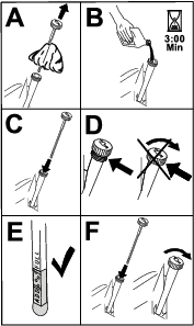
Make sure that the air gap between the center and side electrodes is correct before installing the spark plug. Use a spark plug wrench for removing and installing the spark plug(s) and a gapping tool/feeler gauge to check and adjust the air gap. Install new spark plug(s) if necessary.
Type : Champion® XC10YC or equivalent
Air Gap: 0.76 mm (0.030 inch)
Removing the Spark Plug(s)
-
Park the machine on a level surface, engage the parking brake (if applicable), and lower the grinder.
-
Shut off the engine and remove the key.
-
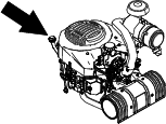
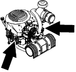
Locate and remove the spark plug(s) as shown in Figure 36.
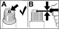
Checking the Spark Plug(s)
Important: Do not clean the spark plug(s). Always replace the spark plug(s) when it has: a black coating, worn electrodes, an oily film, or cracks.
If you see light brown or gray on the insulator, the engine is operating properly. A black coating on the insulator usually means the air cleaner is dirty.
Set the gap to 0.75 mm (0.03 inch).
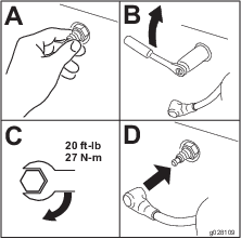
Installing the Spark Plug(s)
Fuel System Maintenance
Danger
In certain conditions, fuel is extremely flammable and highly explosive. A fire or explosion from fuel can burn you and others and can damage property.
Refer to Fuel Safety for a complete list of fuel related precautions.
Draining the Fuel Tank
-
Park the machine on a level surface, engage the parking brake, and lower the grinder.
-
Shut off the engine and remove the key.
-
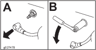
Turn the fuel-shutoff valve to the closed position (Figure 27).
-
Squeeze the ends of the hose clamp on the engine side of the valve together and slide it up the fuel line away from the valve.
-
Pull the fuel line off the valve.
-
Open the fuel-shutoff valve and allow the fuel to drain into a fuel can or drain pan.
Note: If desired, you can replace the fuel filter at this time; refer to Replacing the Low-pressure Fuel Filter.
-
Install the fuel line onto the fuel-shutoff valve. Slide the hose clamp close to the valve to secure the fuel line.
-
Wipe up any spilled fuel.
Replacing the Low-pressure Fuel Filter
| Maintenance Service Interval | Maintenance Procedure |
|---|---|
| Every 150 hours |
|
Never install a dirty filter if it is removed from the fuel line.
Note: Note how the fuel filter is installed in order to install the new filter correctly.
Note: Wipe up any spilled fuel.
-
Park the machine on a level surface, engage the parking brake, and lower the grinder.
-
Shut off the engine and remove the key.
-
Turn the fuel-shutoff valve to the closed position.
-
Squeeze the ends of the hose clamps together and slide them away from the filter (Figure 40).
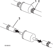
-
Remove the filter from the fuel lines.
-
Install a new filter and move the hose clamps close to the filter.
-
Turn the fuel-shutoff valve to the open position.
-
Check for fuel leaks and repair if needed.
-
Wipe up any spilled fuel.
Servicing the High-Pressure Fuel Filter
Do not attempt to service the high-pressure fuel filter. The high-pressure filter is integrated within the fuel-pump module. The fuel filter and other components inside the fuel-pump module are not serviceable.
Important: Do not attempt to open the fuel-pump module.
Ensure that an Authorized Service Dealer replaces the fuel-pump module with the high-pressure fuel filter.
Electrical System Maintenance
Electrical System Safety
-
Disconnect the battery before repairing the machine. Disconnect the negative terminal first and the positive last. Connect the positive terminal first and the negative last.
-
Charge the battery in an open, well-ventilated area, away from sparks and flames. Unplug the charger before connecting or disconnecting the battery. Wear protective clothing and use insulated tools.
-
Battery acid is poisonous and can cause burns. Avoid contact with skin, eyes, and clothing. Protect your face, eyes, and clothing when working with a battery.
-
Battery gases can explode. Keep cigarettes, sparks, and flames away from the battery.
Servicing the Battery
| Maintenance Service Interval | Maintenance Procedure |
|---|---|
| Every 25 hours |
|
Always keep the battery clean and fully charged. Use a paper towel to clean the battery case. If the battery terminals are corroded, clean them with a solution of 4 parts water and 1 part baking soda. Apply a light coating of grease to the battery terminals to reduce corrosion.
Voltage: 12 V with 350 A (cold cranking) at -18°C (0ºF).
Warning
Battery terminals or metal tools could short against metal machine components, causing sparks. Sparks can cause the battery gasses to explode, resulting in personal injury.
-
When removing or installing the battery, do not allow the battery terminals to touch any metal parts of the machine.
-
Do not allow metal tools to short between the battery terminals and metal parts of the machine.
Removing the Battery
-
Park the machine on a level surface, engage the parking brake, and lower the grinder.
-
Shut off the engine and remove the key.
-
Lift the black rubber cover on the negative cable. Disconnect the negative battery cable from the negative (-) battery terminal (Figure 41).
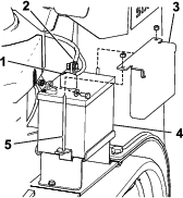
-
Slide the red terminal boot off the positive (red) battery terminal. Then remove the positive (red) battery cable (Figure 41).
-
Remove the hold down plate, j-bolts, and locknuts securing the battery (Figure 41) and remove the battery.
Charging the Battery
Warning
Charging the battery produces gasses that can explode.
Never smoke near the battery and keep sparks and flames away from battery.
Important: Always keep the battery fully charged (1.265 specific gravity). This is especially important to prevent battery damage when the temperature is below 0°C (32°F).
-
Remove the battery from the machine; refer to Removing the Battery.
-
Charge the battery at a rate of 3 to 4 A for 4 to 8 hours (Figure 42). Do not overcharge the battery.
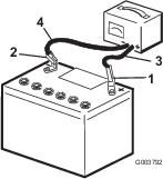
-
When the battery is fully charged, unplug the charger from the electrical outlet, then disconnect the charger leads from the battery posts (Figure 42).
Cleaning the Battery
Note: Keep the terminals and the entire battery case clean, because a dirty battery discharges slowly.
-
Park the machine on a level surface, engage the parking brake, and lower the grinder.
-
Shut off the engine and remove the key.
-
Remove the battery from the machine; Removing the Battery.
-
Wash the entire case with a solution of baking soda and water.
-
Rinse the battery with clear water.
-
Coat the battery posts and cable connectors with Grafo 112X (skin-over) grease (Toro Part No. 505-47) or petroleum jelly to prevent corrosion.
-
Install the battery; refer to Installing the Battery.
Installing the Battery
-
Using the fasteners previously removed, install the positive (red) battery cable to the positive (+) battery terminal (Figure 41).
-
Slide the red terminal boot onto the positive battery post.
-
Using the fasteners previously removed, install the negative (black) battery cable to the negative (-) battery terminal (Figure 41).
-
Secure the battery using the bar and wing nuts (Figure 41).
Important: Ensure that the battery cables do not contact any sharp edges or each other.
Servicing a Replacement Battery
The original battery is maintenance-free and does not require service. For servicing a replacement battery, refer to the battery manufacturer’s instructions.
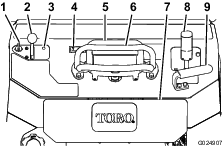
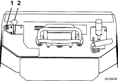
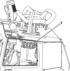
Replacing the Fuses
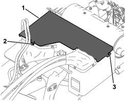
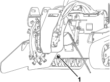
There are 4 fuses in the electrical system. They are under the control panel on the left side (Figure 43).
| Start circuit | 30 A |
| Not used | 5 A |
| Cooler fan circuit | 20 A |
| Headlight (optional) | 15 A |
Drive System Maintenance
Servicing the Tracks
Cleaning the Tracks
| Maintenance Service Interval | Maintenance Procedure |
|---|---|
| Before each use or daily |
|
Check the tracks for excessive wear and clean them periodically. If the tracks are worn, replace them.
-
Park the machine on a level surface, engage the parking brake (if applicable), and lower the grinder.
-
Shut off the engine and remove the key.
-
Using a water hose or pressure washer, remove dirt from each track system.
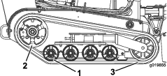
Important: Ensure that you use high-pressure water to wash only the track area. Do not use a high-pressure washer to clean the rest of the machine. High-pressure washing can damage the electrical system and hydraulic valves or deplete grease.
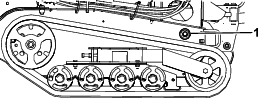
Important: Ensure that you fully clean the road wheels and the drive wheel (Figure 44). The road wheels should rotate freely when clean.
Checking and Adjusting the Track Tension
| Maintenance Service Interval | Maintenance Procedure |
|---|---|
| After the first 50 hours |
|
| Every 100 hours |
|
To check the tension of each track, place 20.4 kg (45 lb) on the track midway between the front road wheel and the drive wheel. The track should flex no more than 0.6 to 1 cm (1/4 to 3/8 inch). If it does, adjust the track tension using the following procedure:

-
Park the machine on a level surface, engage the parking brake (if applicable), and lower the grinder.
-
Shut off the engine and remove the key.
-
Loosen the jam nut on the track tensioning bolt and the clamp bolts on the tension arm (Figure 46).
-
Torque the tensioning bolt to 32.5 to 40 N∙m (24 to 30 ft-lb) to tighten the track (Figure 46).
-
Ensure that the track deflects less than 0.6 to 1 cm (1/4 to 3/8 inch) when 20.6 kg (45 lb) of force is applied to the track span. Adjust the torque on the tensioning bolt as needed.
-
Tighten the jam nut.
-
Tighten the clamp bolts and torque to 102 N∙m (75 ft-lb).
Replacing the Tracks
When the tracks are badly worn, replace them.
-
Park the machine on a level surface, engage the parking brake, and lower the grinder.
-
Shut off the engine and remove the key.
-
Lift/support the side of the unit to be worked on so that the track is 7.6 to 10 cm (3 to 4 inches) off the ground.
-
Back out the tensioning bolt and jam nut (Figure 46).
-
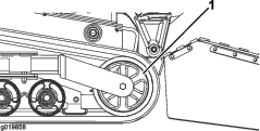
Push the tensioning wheel rearward as far as it will go (Figure 47).
-
Begin removing the track at the top of the tensioning wheel, peeling it off the wheel while rotating the track forward.
-
When the track is off of the tensioning wheel, remove it from the machine (Figure 47).
-
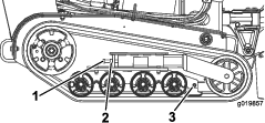
Beginning at the drive wheel, coil the new track around the wheel, ensuring that the lugs on the track fit between the spacers on the wheel (Figure 44).
-
Push the track under and between the rear and center road wheels (Figure 44).
-
Starting at the bottom of the tensioning wheel, install the track around the wheel by rotating the track rearward while pushing the lugs into the wheel.
-
Install the tensioning bolt and jam nut.
-
Torque the tensioning bolt to 32.5 to 40 N∙m (24 to 30 ft-lb) to tighten the track.
-
Ensure that the track deflects less than 0.6 to 1 cm (1/4 to 3/8 inch) when 20.6 kg (45 lb) of force is applied to the track span. Adjust the torque on the tensioning bolt as needed.
-
Tighten the jam nut.
-
Lower the machine to the ground.
-
Repeat the procedure to replace the other track.
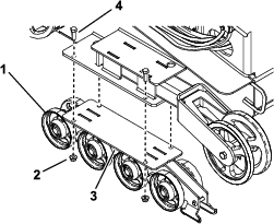
Checking and Greasing the Road Wheels
| Maintenance Service Interval | Maintenance Procedure |
|---|---|
| Every 250 hours |
|
-
Park the machine on a level surface, engage the parking brake, and lower the grinder.
-
Shut off the engine and remove the key.
-
Remove the tracks; refer to Replacing the Tracks.
-
Remove the 4 bolts and nuts securing each lower track guide which contains the road wheels, and remove them (Figure 48).
-
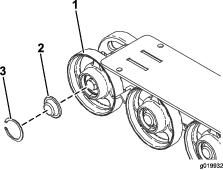
Remove the snap ring and cap from a road wheel (Figure 49).
-
Check the grease under the cap and around the gasket (Figure 49). If it is dirty, gritty, or depleted, clean out all the grease, replace the gasket, and add new grease.
-
Ensure that the road wheel turns smoothly on the bearing. If it is frozen, contact your Authorized Service Dealer to replace the road wheel.
-
Place the greased road wheel cap over the bolt head (Figure 49).
-
Secure the road wheel cap with the snap ring (Figure 49).
-
Repeat steps 5 through 9 for all road wheels.
-
Install each track guide to the traction unit frame using the fasteners you removed previously. Torque the bolts to 91 to 112 N∙m (67 to 83 ft-lb).
-
Install the tracks; refer to Replacing the Tracks.
Cooling System Maintenance
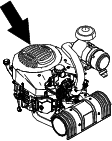
Cleaning the Engine Screen
| Maintenance Service Interval | Maintenance Procedure |
|---|---|
| Before each use or daily |
|
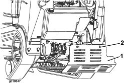
Before each use, remove any buildup of grass, dirt, or other debris from the engine screen. This helps ensure adequate cooling and correct engine speed and reduces the possibility of overheating and mechanical damage to the engine.
Belt Maintenance
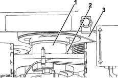
Replacing the Hydrostatic Pump Drive Belt
If the hydrostatic pump drive belt begins to squeal or is cracked, worn, or frayed, replace it. Contact your Authorized Service Dealer for a replacement belt.
-
Park the machine on a level surface, engage the parking brake, and lower the grinder.
-
Shut off the engine and remove the key.
-
Raise the back of the machine and support it on jack stands.
-
Remove the bottom shield; refer to Removing the Bottom Shield.
-
Loosen the set screw on the gear pump drive coupler (Figure 51).
-
Drop the coupler down away from the pulley.
-
Using a spring puller (available from your Authorized Service Dealer) or stiff metal hook, pull the end of the idler pulley spring off the spring bolt to release tension on the belt.
-
Remove the belt.
-
Route a new belt around the pulleys.
-
Install the idler pulley spring on the bolt.
-
Push the coupler up to engage the pulley.
-
Apply thread-locking compound to the coupler set-screw threads and torque it to 10 to 12.6 N∙m (90 to 110 in-lb).
-
Install the bottom shield.
Controls System Maintenance
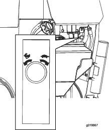
Adjusting the Traction-Control Alignment
The factory adjusts the traction controls before shipping the machine. However, after many hours of use, you may need to adjust the traction-control alignment, the neutral position of the traction control, and the tracking of the traction control in the full forward position.
Important: To adjust the controls properly, complete each procedure in the order listed.
Adjusting the Traction-Control Reverse Position
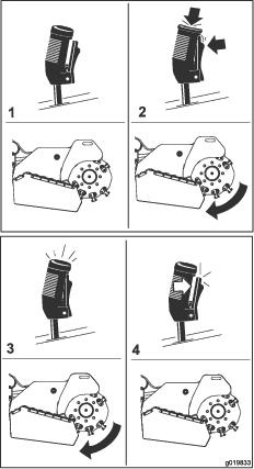
If the traction control bar does not rest flush and square with the reference bar when in the full reverse position, immediately complete the following procedure:
-
Park the machine on a level surface, engage the parking brake (if applicable), and lower the grinder.
-
Shut off the engine and remove the key.
-
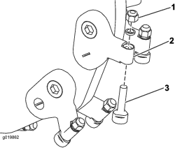
Pull back the traction control so that the front of the control contacts the reference bar (Figure 52).
-
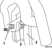
If the front of the traction control does not rest square and flush with the reference bar, loosen the nut and bolt in the stem of the traction control (Figure 53).
-
Adjust the traction control so that it rests flush against the reference bar when it is pulled straight back (Figure 53 and Figure 54).
-
Tighten the flange nut and bolt in the traction control stem.
-
Start the engine.
-
Drive the machine in reverse with the traction control tight to the reference bar. If the machine does not back up straight, complete the following procedure:
-
Shut off the engine
-
Lift and support the machine so that both tracks are off the ground and are free to run.
-
Loosen the flange nut and bolt in the stem of the traction control (Figure 53).
-
Loosen the jam nuts on the traction rods, under the control panel (Figure 55).
-
Start the machine and set the throttle to about the 1/3 open position.
Warning
When the machine is running, you could be caught and injured in moving parts or burned on hot surfaces.
Stay away from pinch points, moving parts, and hot surfaces when adjusting the running machine.
-
Have a helper hold the traction control tight to the reference bar in reverse.
-
Adjust the length of the traction rods until both tracks are running at the same speed.
Note: You can also adjust the maximum reverse speed of the tracks at this time.
-
Tighten the jam nuts.
-
Adjust the traction control so that it rests flush against the reference bar when it is pulled straight back (Figure 53 and Figure 54).
-
Tighten the flange nut and bolt in the traction control stem.
-
Shut off the engine and lower the machine to the ground.
-
Drive the machine in full reverse, checking to see if the machine tracks straight. If it does not, note the direction the machine veers. Repeat the adjustment so that the machine tracks straight in reverse.
-
Adjusting the Traction-Control Neutral Position
If the machine creeps forward or backward when the traction control is in neutral and the machine is warm, you may need to adjust the return-to-neutral mechanism on the pumps; contact your Authorized Service Dealer.
Adjusting the Traction-Control Forward Position
If the machine does not drive straight when you hold the traction control forward against the reference bar, complete the following procedure:
-
Drive the machine with the traction control against the reference bar, noting which direction the machine veers.
-
Release the traction control.
-
If the machine veers to the left, loosen the right jam nut and adjust the tracking set screw on the front of the traction control (Figure 56).
-
If the machine veers to the right, loosen the left jam nut and adjust the tracking set screw on the front of the traction control (Figure 56).
-
Repeat the procedure until the machine drives straight in the full forward position.
Important: Ensure that the set screws touch the stops in the full forward position to avoid overstroking the hydraulic pumps.
Hydraulic System Maintenance
Hydraulic System Safety
-
Seek immediate medical attention if fluid is injected into skin. Injected fluid must be surgically removed within a few hours by a doctor.
-
Ensure that all hydraulic-fluid hoses and lines are in good condition and all hydraulic connections and fittings are tight before applying pressure to the hydraulic system.
-
Keep your body and hands away from pinhole leaks or nozzles that eject high-pressure hydraulic fluid.
-
Use cardboard or paper to find hydraulic leaks.
-
Safely relieve all pressure in the hydraulic system before performing any work on the hydraulic system.
Hydraulic Fluid Specifications
| Maintenance Service Interval | Maintenance Procedure |
|---|---|
| Every 100 hours |
|
| Every 1,500 hours |
|
Hydraulic Tank Capacity: 38 L (10 US gallons)
Use only 1 of the following fluids in the hydraulic system:
-
Toro Premium Transmission/Hydraulic Tractor Fluid (refer to your Authorized Service Dealer for more information)
-
Toro PX Extended Life Hydraulic Fluid (refer to your Authorized Service Dealer for more information)
-
If either of the above Toro fluids are not available, you may use another Universal Tractor Hydraulic Fluid (UTHF), but they must be only conventional, petroleum-based products. The specifications must fall within the listed range for all the following material properties and the fluid should meet the listed industry standards. Check with your hydraulic fluid supplier to determine if the fluid meets these specifications.
Note: Toro will not assume responsibility for damage caused by improper substitutions, so use only products from reputable manufacturers who will stand behind their recommendations.
Material Properties Viscosity, ASTM D445 cSt at 40°C: 55 to 62 cSt at 100°C: 9.1 to 9.8 Viscosity index, ASTM D2270 140 to 152 Pour Point, ASTM D97 -37 to -43°C (-35 to -46°F) Industry Standards API GL-4, AGCO Powerfluid 821 XL, Ford New Holland FNHA-2-C-201.00, Kubota UDT, John Deere J20C, Vickers 35VQ25 and Volvo WB-101/BM Note: Many hydraulic fluids are almost colorless, making it difficult to spot leaks. A red dye additive for the hydraulic system fluid is available in 20 ml (0.67 fl oz) bottles. One bottle is sufficient for 15 to 22 L (4 to 6 US gallons) of hydraulic fluid. Order Part No. 44-2500 from your Authorized Service Dealer.
Checking the Hydraulic-Fluid Level
| Maintenance Service Interval | Maintenance Procedure |
|---|---|
| Every 25 hours |
|
Refer to Hydraulic Fluid Specifications for hydraulic fluid specifications.
-
Park the machine on a level surface, engage the parking brake (if applicable), and lower the grinder.
-
Shut off the engine and remove the key.
-
Look into the glass bubble on the right side of the machine. If you cannot see hydraulic fluid in the bubble, continue this procedure to add fluid.
-
Remove the front cover; refer to Removing the Front Cover.
-
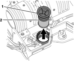
Clean the area around the filler neck of the hydraulic tank and remove the cap and filter from the filler neck using a socket (Figure 58).
-
If the level is low, add fluid until it is visible in the glass bubble.
-
Install the cap and filter on the filler neck and torque bolt on top to 21 to 25 N∙m (200 to 240 in-lb).
-
Install the front cover; refer to Removing the Front Cover.
Replacing the Hydraulic Filter
| Maintenance Service Interval | Maintenance Procedure |
|---|---|
| Every 200 hours |
|
-
Park the machine on a level surface, engage the parking brake (if applicable), and lower the grinder.
-
Shut off the engine and remove the key.
-
Remove the front cover; refer to Removing the Front Cover.
-
Remove and discard the old filter (Figure 58).
-
Install the replacement hydraulic filter and filler cap (Figure 58) and torque the bolt on top to 21 to 25 N∙m (200 to 240 inch-lb).
-
Clean up any spilled fluid.
-
Install the top cover.
Changing the Hydraulic Fluid
| Maintenance Service Interval | Maintenance Procedure |
|---|---|
| Every 400 hours |
|
-
Park the machine on a level surface, engage the parking brake, and lower the grinder.
-
Shut off the engine and remove the key.
-
Allow the machine to cool completely.
-
Remove the top cover.
-
Remove the hydraulic-tank filler cap and filter (Figure 58).
-
Place a drain pan capable of holding 38 L (10 US gallons) under the hydraulic tank.
-
Remove the hydraulic tank drain plug and allow the fluid to drain into the pan (Figure 59).
-
When finished, install and tighten the drain plug.
Note: Dispose of the used oil at a certified recycling center.
-
Fill the hydraulic tank with hydraulic fluid; refer to Hydraulic Fluid Specifications.
-
Install the hydraulic filter and filler cap (Figure 58) and torque bolt on top to 21 to 25 N∙m (200 to 240 inch-lb).
-
Start the engine and let it run for a few minutes.
-
Shut off the engine.
-
Check the hydraulic fluid level and add any fluid if necessary; refer to Checking the Hydraulic-Fluid Level.
-
Clean up any spilled fluid.
-
Install the top cover.
Grinder Maintenance
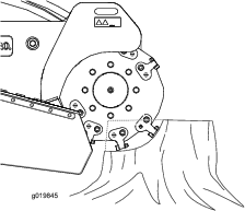
Replacing the Teeth
| Maintenance Service Interval | Maintenance Procedure |
|---|---|
| Before each use or daily |
|
Due to the high amount of wear placed on the teeth, you need to rotate and replace them periodically (Figure 60).
Each tooth is indexed with 3 positions so you can rotate it twice, exposing a new sharp edge before replacing the tooth. To rotate a tooth, loosen the nut securing the tooth (Figure 61). Push the tooth forward and rotate it one third of a turn, bringing an unused edge to the outside. Torque the nut securing the tooth to 68 N∙m (50 ft-lb).
To replace a tooth, remove the nut securing the tooth to remove it, then install a new tooth, spacer, and nut in the same position (Figure 61). Torque the nut securing the tooth to 68 N∙m (50 ft-lb).
Cleaning
Removing Debris from the Machine
| Maintenance Service Interval | Maintenance Procedure |
|---|---|
| After each use |
|
Important: Operating the engine with blocked screens, dirty or plugged cooling fins, and/or cooling shrouds removed will result in engine damage from overheating.
-
Park the machine on a level surface, engage the parking brake (if applicable), and lower the grinder.
-
Shut off the engine, remove the key, and wait for the engine to cool.
-
Wipe away debris from the air cleaner.
-
Clean any debris buildup on the engine and muffler with a brush or blower.
Important: It is preferable to blow dirt out, rather than washing it out. If you use water, keep it away from electrical items and hydraulic valves. Do not use a high-pressure washer. High-pressure washing can damage the electrical system and hydraulic valves or deplete grease.
-
Clean debris from the oil cooler.