Installation
Preparing the Machine
Warning
Tipping the machine may cause the fuel to leak. Fuel is flammable and explosive, and can cause personal injury.
Run the engine dry or remove the fuel with a hand pump; never siphon the fuel.
-
Run the engine dry or remove the fuel with a hand pump.
-
Move the machine to a level surface, shut off the engine, wait for all moving parts to stop, and allow the engine to cool.
-
Disconnect the spark-plug wire from the spark plug; refer to the Operator’s Manual for your machine.
Removing the Roller
Parts needed for this procedure:
| Bearing support plate | 2 |
| Bolt (M6 x 16) | 3 |
| Rear roller bushing | 2 |
| Thrust washer (36 mm) | 2 |
| Drive cam | 4 |
| Drive key | 4 |
| Roller bushing | 2 |
| Flat washer | 6 |
| Spacer | 1 |
| Shaft | 1 |
| Sprocket (22T) | 1 |
| Washer (M6 x 18) | 1 |
| Bolt (M6 x 20) | 1 |
-
If the grass bag is on the machine, remove the grass bag.
-
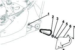
Remove the chain cover from the machine by removing the 2 chain-cover bolts (Figure 1).
Note: Retain the chain cover and 2 chain-cover bolts for later installation.
-
Remove and discard the existing circlip, thrust washer, sprocket, and chain from the gearbox post (Figure 1).
-
Remove the roller and all corresponding parts from the machine.
Note: Discard all corresponding parts except the roller itself.
-
Fill the cam drive cavity with grease that has superior water resistance such as Fuchs Renolit CZ2 grease or similar.
Important: Do not use standard grease as this may allow moisture to reduce lubricant efficiency.
-
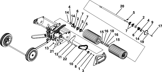
Replace all roller parts as shown in Figure 2.
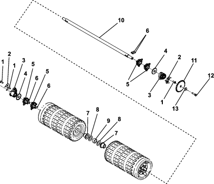
Note: Add multiple flat washers to remove sideways movement.
-
Apply thread-locking compound (Loctite 2701 or similar) on the bolt (M6 x 20). Install and torque the bolt to 11 N·m (8 ft-lb). Allow the bolt to cure for 6 hours.
-
When shimming the rear roller, only tighten to remove end float. Do not tighten to the point where the roller locks up or the roller has too much resistance when rotating.
Finishing the Installation
Parts needed for this procedure:
| Tensioner template | 1 |
| Tensioner pulley | 1 |
| Cap head bolt (M6 x 35) | 1 |
| Nut | 1 |
| Back plate | 1 |
| Chain | 1 |
| Sprocket (10T) | 1 |
| Thrust washer (20 mm) | 1 |
| Circlip | 1 |
-
Line up the tensioner template on the rear axle support and temporarily fix the template in place using a chain cover bolt in the corresponding hole.
-
Drill 4 pilot holes [3 mm (1/8 inch)] in the rear axle support in the locations marked.
-
Remove the template from the machine and discard.
-
Use a 6 mm (1/4 inch) drill bit to open up the 4 holes.
Note: The holes will overlap. This is intentional.
-
Install the tensioner pulley in one of the 4 holes that you drilled. Use cap head bolt (M6 x 35) to secure the pulley to the rear axle support.
-
Install the back plate on the back of the rear axle support and secure the bolt with the nut.
-
Gently push up the chain with the idler until you get adequate tension. Push the bolt through the nearest available clear hole. Do not force the bolt through a partial hole and over tension the chain. The additional holes allow for future adjustment.
-
Install the chain, sprocket (10T), thrust washer (20 mm), and circlip onto the gearbox post as shown in Figure 3.
-
Secure the previously removed chain cover onto the machine with the 2 corresponding bolts (Figure 3).
| Ref. | Part Number | Qty. | Description |
| 1 | 111-8216 | 1 | Washer-thrust |
| 2 | 111-8602 | 2 | Washer-thrust |
| 3 | 134-0254 | 2 | Circlip |
| 4 | 134-1734 | 2 | Bearing support plate |
| 5 | 134-2034 | 4 | Key drive |
| 6 | 134-2635 | 2 | Rear roller bushing |
| 7 | 134-2924 | 4 | Drive cam |
| 8 | 134-3805 | 1 | Sprocket (10T) |
| 9 | 134-3806 | 1 | Sprocket (22T) |
| 10 | 134-5261 | 1 | Chain |
| 11 | 134-6226 | 1 | Tensioner pulley |
| Ref. | Part Number | Qty. | Description |
| 12 | 134-6282 | 1 | Tensioner template |
| 13 | 09438 | 1 | Nut |
| 14 | 09545 | 4 | Bolt (M6 x 16) |
| 15 | 340129 | 2 | Roller bushing |
| 16 | 480097 | 6 | Flat washer |
| 17 | ZBHIF025U | 1 | Bolt (M6 x 20) |
| 18 | 134-0314 | 1 | Roller spacer |
| 19 | 111–7679 | 1 | Washer (M6 x 18) |
| 20 | 134-5253 | 1 | Roller shaft |
| 21 | 134-6225-03 | 1 | Tensioner back plate |
| 22 | 111-0118 | 1 | Cap head bolt (M6 x 35) |