Disclaimers and Regulatory Information
It is a violation of California Public Resource Code Section 4442 or 4443 to use or operate the engine on any forest-covered,
brush-covered, or grass-covered land unless the engine is equipped with a spark arrester, as defined in Section 4442, maintained
in effective working order or the engine is constructed, equipped, and maintained for the prevention of fire.
Because in some areas there are local, state, or federal regulations requiring that a spark arrester be used on the engine
of this machine, a spark arrester is available as an option. If you require a spark arrester, contact your Authorized Service
Dealer. Genuine Toro spark arresters are approved by the USDA Forestry Service.
The enclosed engine owner's manual is supplied for information regarding the US Environmental Protection Agency (EPA) and
the California Emission Control Regulation of emission systems, maintenance, and warranty. Replacements may be ordered through
the engine manufacturer.
 |
| |
| CALIFORNIA |
| |
| Proposition 65 |
| |
| The engine exhaust from this product contains chemicals known to
the State of California to cause cancer, birth defects, or other reproductive
harm. |
| |
| Battery posts, terminals, and related accessories contain lead and
lead compounds, chemicals known to the State of California to cause
cancer and reproductive harm. Wash hands after handling. |
| |
| Use of this product may cause exposure to chemicals known to the
State of California to cause cancer, birth defects, or other reproductive
harm. |
| |
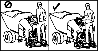
Intended Use
This machine is intended to be used by professional, hired operators in commercial applications. This machine is a stable,
reliable, and productive machine for carrying and moving materials for any job site. It is primarily designed to move concrete,
mortar, gravel, dirt, or debris around job sites. Using this product for purposes other than its intended use could prove
dangerous to you and bystanders.
Read this information carefully to learn how to operate and maintain your product properly and to avoid injury and product
damage. You are responsible for operating the product properly and safely.
Getting Help
Visit www.Toro.com for product safety and operation training materials, accessory information, help finding a dealer, or to register your product.
Whenever you need service, genuine Toro parts, or additional information, contact an Authorized Service Dealer or Toro Customer Service and have the model and serial numbers of your product ready. These numbers are located on the serial plate
on your product  . Write the numbers in the space provided.
With your mobile device, you can scan the QR code on the serial number decal (if equipped) to access warranty, parts, and
other product information.
|
Model Number:
|
|
Serial Number:
|
|
Manual Conventions
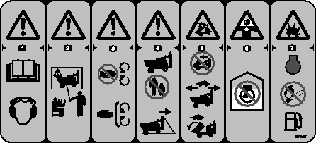
This manual identifies potential hazards and has safety messages identified by the safety-alert symbol, which signals a hazard
that may cause serious injury or death if you do not follow the recommended precautions.
This manual uses 2 words to highlight information. Important calls attention to special mechanical information and Note emphasizes general information worthy of special attention.
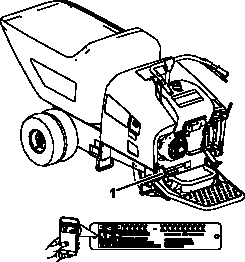
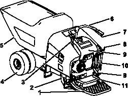
G356654
- Operator platform
- Steer tires
- Reverse-speed-control lever
- Drive tires
- Hopper
- Handle bars
- Forward-speed-control lever
- Dump handle/pedal
- Fuel tank
- Parking brake
- Brake pedal
Controls
Brake Pedal
Press down on the brake pedal to stop the machine.
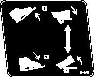
Dump Controls
g025722
- Dump switch
- Dump pedal
- Lower the hopper
- Dump the hopper
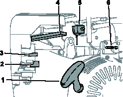
Engine Controls
G356777
- Recoil starter
- Fuel shut-off valve
- Choke lever
- Throttle lever
- Fuel tank shut off valve
- On/Off switch
Choke Control
G356784
- Engage the choke before starting a cold engine.
- Disengage the choke when the engine is warm.
Fuel Shutoff Controls
g356785
- Fuel tank shutoff control—use when performing maintenance and storing the machine.
- Engine fuel shutoff control—use before starting and after stopping the machine.
- Off
- On
Recoil Starter
Use the recoil starter handle to start the engine.
Specifications
Note: Specifications and design are subject to change without notice.
|
Width (single wheel)
|
86 cm (34 inches)
|
|
Width (single wheel)
|
117 cm (46 inches)
|
|
Length
|
268 cm (105.5 inches)
|
|
Height
|
114.3 cm (45 inches)
|
|
Weight
|
621 kg (1370 lb)
|
|
Hopper capacity
|
0.45 m3 (16 cu.ft.)
|
|
Maximum load
|
1136 kg (2500 lb)
|
|
Maximum load (single wheel)
|
850 kg (1875 lb)
|
|
Wheelbase
|
107 cm (42 inches)
|
|
Discharge height
|
16.5 cm (6.5 inches)
|
Attachments/Accessories
A selection of Toro approved attachments and accessories is available for use with the machine to enhance and expand its capabilities. Contact
your Authorized Service Dealer or authorized Toro distributor or go to www.Toro.com for a list of all approved attachments and accessories.
To ensure optimum performance and continued safety certification of the machine, use only genuine Toro replacement parts and accessories. Replacement parts and accessories made by other manufacturers could be dangerous, and
such use could void the product warranty.
Note: Determine the left and right sides of the machine from the normal operating position.
Refer to your engine owner's manual for additional maintenance procedures.
Maintenance Safety
- Park the machine on a level surface, engage the parking brake, and shut off the engine. Wait for all movement to stop and
allow the machine to cool before adjusting, servicing, cleaning, or storing the machine.
- Disconnect the battery or remove the spark-plug wire before making any repairs. Disconnect the negative terminal first and
the positive terminal last. Connect the positive terminal first and negative last.
- Charge the batteries in an open, well-ventilated area, away from spark and flames. Unplug the charger before connecting or
disconnecting it from the battery. Wear protective clothing and use insulated tools.
- Battery acid is poisonous and can cause burns. Avoid contact with skin, eyes, and clothing. Protect your face, eyes, and clothing
when working with a battery.
- Battery gasses can explode. Keep cigarettes, sparks, and flames away from the battery.
- Do not change the engine governor setting or overspeed the engine.
- Support the machine with jack stands whenever you work under the machine.
- Carefully release pressure from components with stored energy.
- Keep all parts in good working condition and all hardware tightened. Replace all worn or damaged decals.
- Use the cylinder lock to secure the hopper in the raised position.
- Never tamper with safety devices.
- To ensure safe, optimal performance of the machine, use only genuine Toro replacement parts. Replacement parts made by other manufacturers could be dangerous, and such use could void the product
warranty.
- Seek immediate medical attention if fluid is injected into skin. Injected fluid must be surgically removed within a few hours
by a doctor.
- Ensure that all hydraulic-fluid hoses and lines are in good condition and all hydraulic connections and fittings are tight
before applying pressure to the hydraulic system. Keep your body and hands away from pinhole leaks or nozzles that eject high-pressure
hydraulic fluid.
- Use cardboard or paper to find hydraulic leaks.
- Safely relieve all pressure in the hydraulic system before performing any work on the hydraulic system.
Recommended Maintenance Schedule
|
After the first 50 hours
|
|
- |
- |
- |
|
Before each use or daily
|
|
- |
- |
- |
|
|
- |
- |
- |
|
|
- |
- |
- |
|
|
- |
- |
- |
|
|
- |
- |
- |
|
Check for loose fasteners.
|
- |
- |
- |
|
Every 40 hours
|
|
- |
- |
- |
|
|
- |
- |
- |
|
|
- |
- |
- |
|
Every 50 hours
|
|
- |
- |
- |
|
|
- |
- |
- |
|
Every 100 hours
|
|
- |
- |
- |
|
|
- |
- |
- |
|
|
- |
- |
- |
|
|
ST45150 |
1 |
Hydraulic filter |
|
Every 200 hours
|
|
- |
- |
- |
|
Every 300 hours
|
|
- |
- |
- |
|
|
- |
- |
- |
|
|
- |
- |
- |
|
Every 1,000 hours
|
|
- |
- |
- |
|
Every 1,500 hours
|
Replace all moving hydraulic hoses.
|
125-8569 |
1 |
Hydraulic hose |
|
125-8570 |
1 |
Hydraulic hose |
|
Yearly
|
Pack wheel bearings.
|
- |
- |
- |
|
Yearly or before storage
|
Touch up chipped paint.
|
361-9 |
1 |
Paint |
|
361-10 |
1 |
Paint |
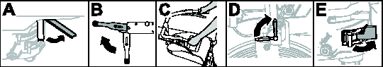
Pre-Maintenance Procedures
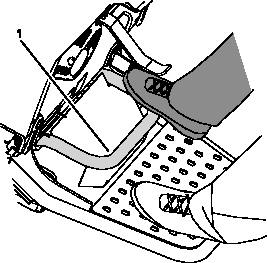
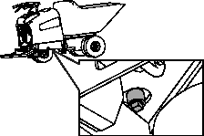
Moving a Non-Functional Machine
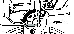
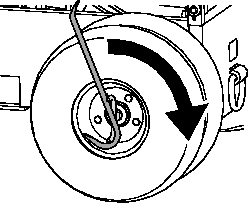
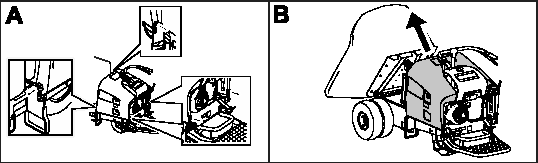
In an emergency, you can move the machine forward by actuating the bypass valve in the hydraulic pump and pushing or towing the machine.
Do not tow or pull the machine without bypassing the parking brake or you will damage the hydraulic system.
-
Place the hopper in the dump position and remove the cowl.
-
Rotate the bypass valve counterclockwise to tow the machine.
-
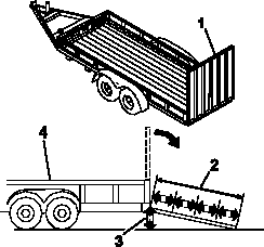
Tow the machine as required using the tie down locations.
Do not push or tow the machine faster than 3 to 4.8 km/h (2 to 3 mph) for longer than 3 minutes, because you may damage the
transmission. The bypass valves must be open whenever you push or tow the machine.
-
Rotate the bypass valve clockwise to operate the machine normally.
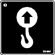
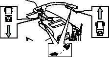
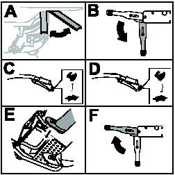
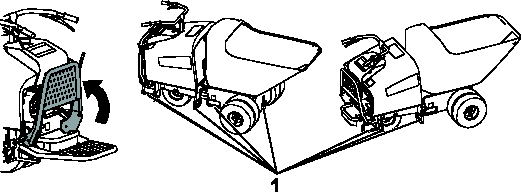
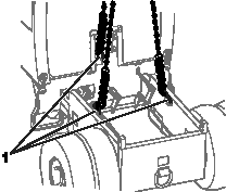
Lifting the Machine
Lifting the Machine with a Hoist
Ensure that the hopper is empty before lifting the machine.
-
Place the platform in the raised position.
-
Place the hopper in the dump position.
-
Attach a chain or straps to each of the 3 lift points located under the hopper.
-
Remove any slack in the chains or straps to ensure that the machine is properly balanced.
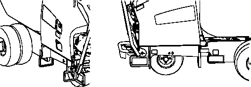
Lifting the Machine with a Forklift
Ensure that the hopper is empty before lifting the machine.
-
Place the platform in the raised position.
-
Lift the machine using the side or rear pockets.
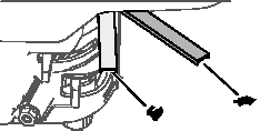
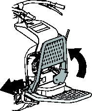
Removing the Cowl
-
Place the hopper in the dump position.
-
Shut off the engine and allow the engine to cool.
-
Unhook the cowl latches and remove the cowl.
-
When finished, install the cowl and secure the latches.
Lubrication
Greasing the Machine
Grease Type: General-purpose grease.
Note: Remove the blue protection caps, if applicable, before greasing and replace when finished.
-
Park the machine on a level surface and engage the parking brake.
-
Shut off the engine and allow the engine to cool.
-
Clean the grease fittings with a rag.
-
Connect a grease gun to each fitting.
-
Pump grease into the fittings until grease begins to ooze out of the bearings (approximately 3 pumps).
-
Wipe up any excess grease.
Engine Maintenance
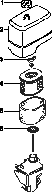
Servicing the Air Cleaner
Do not operate the engine without the air-cleaner element. Operating without an element causes damage to the engine.
-
Disconnect the spark-plug wire.
-
Remove the wing nut that secures the air-cleaner cover to the air cleaner and remove the cover  . Clean the cover thoroughly.
-
Remove the wing nut  from the air filter and remove the filter.
-
Remove the foam filter  from the paper filter
  .
.
-
Inspect both air-filter elements and replace them if they are damaged.
Note: Always replace the paper air-filter element at the scheduled interval.
-
Clean the foam element as follows:
-
A. Wash the foam element in a solution of liquid soap and warm water.
Note: Squeeze to remove dirt, but do not twist the element because the foam may tear.
-
B. Dry the element by wrapping in a clean rag. Squeeze the rag and foam element to dry, but do not twist the element because
the foam may tear.
-
C. Saturate the element with clean engine oil. Squeeze element to remove excess oil and to distribute oil thoroughly.
-
Clean the paper element by tapping the filter element several times on a hard surface or blow compressed air (not exceeding
2.07 bar (30 psi)) through the paper element from the inside.
Note: Never try to brush off the dirt; brushing the paper element will force the dirt into the fibers.
-
Install the foam element, paper element, and air-cleaner cover.
Engine Oil Service
Engine Oil Specifications
|
Crankcase capacity:
|
1.1 L (1.16 US qt)
|
|
Oil type:
|
API classification SJ or later.
|
|
Oil viscosity:
|
Selected the oil viscosity according to ambient temperature in the table below.
|
|
Over 13° C (40° F)
|
SAE 30 or 10W30
|
|
Below 13° C (40° F)
|
SAE 20 or 10W30
|
Checking the Engine-Oil Level
-
Park the machine on a level surface and shut off the engine. Allow the engine to cool.
-
Unlatch and remove the cowl.
-
Clean around the oil filler cap/dipstick .
-
Remove the oil filler cap/dipstick by rotating it counterclockwise.
-
Wipe the oil filler cap/dipstick clean and insert it into filler port .
Note: Do not screw it into the port.
Do not overfill the crankcase with oil because the engine may be damaged.
-
Remove and check level of oil.
Note: If oil level is near or below the lower limit mark on the dipstick, add only enough of the specified oil to raise level to the upper limit mark (bottom edge of the oil fill hole).
-
Check level of oil.
-
Install the oil filler cap/dipstick and wipe up any spilled oil.
-
Install the cowl and secure the latches.
Changing the Engine-Oil
-
Start the engine and let it run for 5 minutes.
Note: This warms the oil so that it drains better.
-
Park the machine on a level surface, engage the parking brake, and shut off the engine.
-
Have a funnel ready to place under the oil drain plug, then remove the plug and place the funnel under the plug to guide the
oil into a container.
 |
Caution |
|
Components will be hot if the machine has been running. If you touch hot components, you may be burned.
Use care to avoid touching hot components while changing the oil and/or filter.
-
Install the drain plug and wipe away excess oil from the machine.
-
Fill the crankcase with the specified oil.
-
Dispose of the oil properly. Recycle the used oil according to local codes.
Replacing the Spark Plug
-
Remove the spark-plug wire.
-
Clean around spark plug and remove plug from cylinder head.
Note: Replace a cracked, fouled, or dirty spark plug. Do not sand blast, scrape, or clean electrodes because engine damaged could
result from grit entering the cylinder.
-
Set the air gap at 0.70 to 0.80 mm (0.028 to 0.031 inch) . Install the spark plug carefully by hand to avoid cross-threading.
-
After the spark plug is seated, tighten it with a spark plug wrench to compress the sealing washer.
-
When installing a new spark plug, tighten 1/2 turn after the spark plug seats to compress the washer.
-
When installing the original spark plug, tighten 1/8 to 1/4 turn after the spark plug seats to compress the washer.
Note: A loose spark plug can overheat and damage the engine. Overtightening the spark plug can damage the threads in the cylinder
head.
-
Connect the spark-plug wire.
Cleaning the Blower Housing
To ensure proper cooling, ensure that the cooling fins and other external surfaces of the engine are kept clean at all times.
Ensure that the cooling shrouds are installed.
Operating the engine with dirty or plugged cooling fins and/or cooling shrouds removed causes engine damage due to overheating.
-
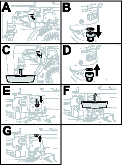
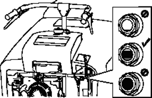
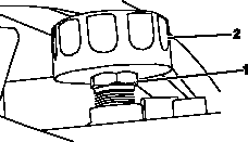
Fuel System Maintenance
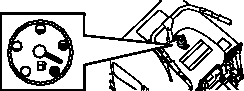
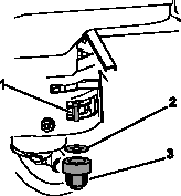
Cleaning the Sediment Cup
-
Move the fuel valve to the Off position .
-
Remove the fuel sediment cup and O-ring .
-
Wash the sediment cup and O-ring in nonflammable solvent, and dry them thoroughly.
-
Place the O-ring in the fuel valve, and install the sediment cup.
-
Tighten the sediment cup securely.
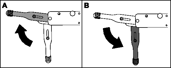
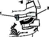
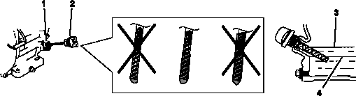
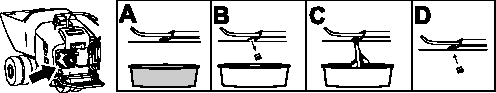
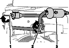
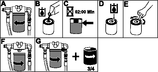
Replacing the Fuel Filter
-
Park the machine on a level surface, shut off the engine, engage the parking brake, and allow the engine to cool.
-
Rotate the lever for the tank-shutoff valve forward and up to the Off position.
-
Start the engine and run the machine until the engine shuts off.
-
Rotate the engine switch clockwise to the Stop position, and allow the engine to cool.
-
Remove the spark-plug wire.
-
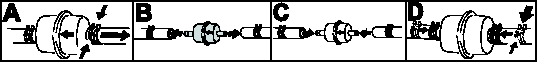
Replace the filter .
Note: Ensure that the flow-direction arrow on the replacement filter points toward the engine.
-
Connect the spark plug wire.
-
Open the tank shutoff valve and turn on the engine switch, and check for fuel leaks.
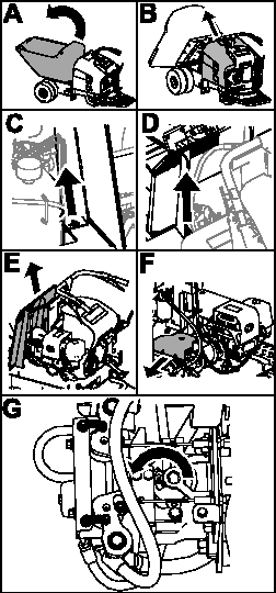
Drive System Maintenance
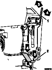
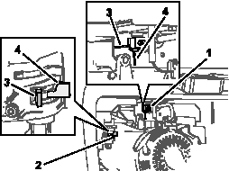
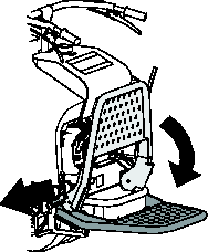
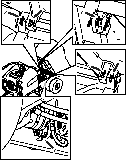
Checking the Transmission Neutral Position
If the machine creeps in any direction when you release the controls, adjust the transmission neutral position.
-
Put the hopper in the dump position  and shut off the engine.
-
Remove the cowl  .
.
-
Remove the throttle lever cables at the transmission.
-
Lift the front wheels off the ground, and support the machine with a jack stand.
-
Start the machine. Increase the engine throttle to full speed while checking for front drive wheel rotation.
Note: If the wheels rotate, proceed to the next step. If the wheels do not rotate, shut off the engine and install the control
cables and cowl.
-
Note the directional movement of the front drive wheels. Shut off the engine.
-
Remove the hardware securing the screen to the frame  and
and  .
.
-
Remove the screen  .
.
-
Remove the transmission cover plate  .
.
-
Loosen the lock down screw  until the return arm can be rotated.
Note: If wheels rotate forward, rotate the return arm counterclockwise. If wheels rotate backward, rotate the return arm clockwise.
-
Tighten the lock down screw and check the front drive wheel rotation.
Inspecting the Tires
-
Inspect tires for cuts, slashes, or bulges. Tires with defects need to be replaced or repaired for proper handling and safety.
Torquing the Wheel Lug Nuts
-
Torque the lug nuts at the front and rear wheels in a crossing pattern to 122 N∙m (90 ft-lb).
Brake Maintenance
Checking the Brake Pedal
-
Move the machine to a level, open area.
-
Engage the parking brake and start the engine.
-
Set the engine throttle to the Fast position.
-
Step on the brake pedal .
-
Disengage the parking brake.
-
Slowly squeeze the forward speed-control lever.
The machine should not move forward and the engine should stall at full engagement of the speed control.
-
Release the speed-control lever.
-
If the machine moves forward or backward, bring the machine to an Authorized Service Dealer.
Checking the Parking Brake
-
Move the machine to a level, open area.
-
Engage the parking brake and start the engine.
-
Set the engine throttle to the Fast position.
-
Slowly squeeze the forward speed-control lever.
The machine should not move forward and the engine should stall at full engagement of the speed control. If the machine moves
forward, adjust the parking brake.
-
Release the speed-control lever.
-
Disengage the parking brake.
-
Slowly squeeze the forward speed-control lever.
The machine should move forward. If the machine does not move forward, adjust the parking brake.
-
Repeat the steps above for the reverse speed control lever.
-
Step on the brake pedal, engage the parking brake, and shut off the engine.
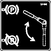
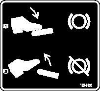
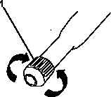
Adjusting the Parking Brake
-
Shut off the engine.
-
Step on the brake pedal.
-
Disengage the parking brake.
-
Rotate the knob to adjust the parking brake.
- Counterclockwise—loosen
- Clockwise—tighten
Note: Rotate the knob no more than 1 revolution each time.
-
Test the parking brake.
-
Repeat steps above until the machine does not move forward.
Hydraulic System Maintenance
Hydraulic Fluid Specifications
|
Hydraulic-Fluid type:
|
Mobil 424 Hydraulic Oil or equivalent
|
|
Hydraulic fluid capacity:
|
28.4 L (30 US qt)
|
The machine hydraulic tank is filled at the factory with approximately 28.4 L (30 US qt) of hydraulic fluid.
Use only 1 of the following fluids in the hydraulic system:
- Toro Premium Transmission/Hydraulic Tractor Fluid (refer to your Authorized Service Dealer for more information)
- Toro PX Extended Life Hydraulic Fluid (refer to your Authorized Service Dealer for more information)
- If either of the above Toro fluids are not available, you may use another Universal Tractor Hydraulic Fluid (UTHF), but they must be only conventional, petroleum-based products. The specifications must fall within the listed range for all the following material properties and the fluid should
meet the listed industry standards. Check with your hydraulic fluid supplier to determine if the fluid meets these specifications.
Note: Toro will not assume responsibility for damage caused by improper substitutions, so use only products from reputable manufacturers
who will stand behind their recommendations.
| Material Properties |
| Viscosity, ASTM D445 |
cSt at 40°C: 55 to 62 |
| cSt at 100°C: 9.1 to 9.8 |
| Viscosity index, ASTM D2270 |
140 to 152 |
| Pour Point, ASTM D97 |
-37 to -43°C (-35 to -46°F) |
| Industry Standards |
| API GL-4, AGCO Powerfluid 821 XL, Ford New Holland FNHA-2-C-201.00, Kubota UDT, John Deere J20C, Vickers 35VQ25 and Volvo
WB-101/BM |
Note: Many hydraulic fluids are almost colorless, making it difficult to spot leaks. A red dye additive for the hydraulic system
fluid is available in 20 ml (2/3 fl oz) bottles. One bottle is sufficient for 15 to 22 L (4 to 6 US gallons) of hydraulic
fluid. Order Part No. 44-2500 from your Authorized Toro Dealer.
Checking the Hydraulic Fluid
|
Caution |
|
The hydraulic breather/filler cap is designed to pressurize the reservoir to 34 kPa (5 psi).
Loosen the cap slowly to avoid injury whenever adding oil or working on the hydraulic system. Use a wrench on the hex directly
under the cap.
-
Park the machine on a level surface, lower the hopper, shut off the engine, and allow the engine to cool.
-
Check the fluid level on the sight gauge.
Note: When the fluid level is correct, the fluid level will cover 25% to 75% of the window in the sight gauge.
-
If the fluid level is low, add enough of the specified hydraulic to raise it to the proper level.
-
A. Unlatch and remove the cowl.
-
B. Slowly loosen the hex nut on the bottom of the cap .
-
C. Add the fluid to the hydraulic tank.
-
D. Install the breather/filler cap and wipe up any spilled fluid.
-
E. Install and latch the cowl.
Changing the Hydraulic Fluid
-
Park the machine on a level surface, shut off the engine, and allow the engine to cool.
-
Unlatch and remove the cowl.
-
Slowly loosen the hex nut on the bottom of the cap.
|
Caution |
|
The hydraulic breather/filler cap is designed to pressurize the reservoir to 34 kPa (5 psi).
Loosen the cap slowly to avoid injury whenever adding oil or working on the hydraulic system. Use a wrench on the hex directly
under the cap.
-
Place a large drain pan under the drain plug located at the bottom of the hydraulic tank.
-
Remove the drain plug and allow the oil to drain into the pan.
-
Install and tighten the drain plug.
Note: Dispose of the used oil at a certified recycling center.
-
Fill the hydraulic tank with the proper hydraulic fluid.
-
Start the engine and let it run for a 2 to 3 minutes.
-
Shut off the engine.
-
Check the hydraulic fluid level and add more fluid if necessary.
-
Install the cowl and secure the latches.
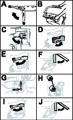
Replacing the Hydraulic Filter
Do not use an automotive oil filter or severe hydraulic system damage may result.
-
Park the machine on a level surface, shut off the engine, and allow the engine to cool.
-
Unlatch and remove the cowl.
-
Place a drain pan under the filter and replace it as shown:
-
Clean up any spilled fluid.
-
Start the engine and let it run for 2 minutes to purge air from the system.
-
Shut off the engine and check for leaks.
-
Check the fluid level in the hydraulic tank.
-
Install the cowl and secure the latches.
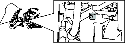
Checking the Hydraulic Lines
-
Check the hydraulic lines for leaks, loose fittings, kinked lines, loose mounting supports, wear, and deterioration. Make
necessary repairs before operating.
Cleaning
Removing Debris
Operating the engine with blocked screens, dirty or plugged cooling fins, and/or cooling shrouds removed, will result in engine
damage from overheating.
-
Park the machine on a level surface and shut off the engine. Allow the engine to cool.
-
Unlatch and remove the cowl.
-
Clean any debris from under the hopper.
-
Wipe away debris from the air cleaner.
-
Clean any debris buildup on the engine and in the transmission with a brush or blower.
It is preferable to blow dirt out rather than washing it out. If you use water, keep it away from electrical items and hydraulic
valves.
Do not use a high-pressure washer. High-pressure washing can damage the electrical system and hydraulic valves or deplete
grease.
The engine does not start.
|
Possible Cause
|
Corrective Action
|
|
The On/Off switch is in the Off position.
|
-
Move the switch to the On position.
|
|
The fuel-shutoff valve is closed.
|
-
Open the fuel-shutoff valve.
|
|
The engine oil is low. Before the oil level in the crankcase can fall below a safe limit, the oil alert system will automatically
shut off the engine.
|
-
Check the engine oil.
|
|
The choke is open.
|
-
Close the choke when starting a cold engine.
|
|
The fuel tank is empty.
|
-
Fill the tank with fresh fuel.
|
|
The spark plug wire is loose or disconnected.
|
-
Check the electrode gap and clean or replace the spark plug.
|
The engine runs rough.
|
Possible Cause
|
Corrective Action
|
|
The choke is closed.
|
-
Open the choke.
|
|
The air filter is clogged.
|
-
Clean or replace the air filter. .
|
|
The fuel line is clogged.
|
-
Clean the sediment cup.
|
|
There is water or contaminants in the fuel.
|
-
Drain the fuel tank and fill it with fresh fuel.
|
|
The spark plugs are worn or have buildup on the electrodes.
|
-
Check the electrode gap and clean or replace the spark plug.
|
The machine does not drive.
|
Possible Cause
|
Corrective Action
|
|
The hydraulic-fluid in the transmission is low.
|
-
Add hydraulic fluid to the hydraulic fluid expansion tank.
|
|
Air is in the hydraulic system.
|
-
Bleed the air out the hydraulic system.
|
|
The parking brake is engaged.
|
-
Disengage the parking brake.
|
The machine does not stop.
|
Possible Cause
|
Corrective Action
|
|
The hydraulic or transmission system is damaged.
|
-
Contact your Authorized Service Dealer.
|
California Proposition 65 Warning Information
What is this warning?
You may see a product for sale that has a warning label like the following:
 |
WARNING: Cancer and Reproductive Harm—www.p65Warnings.ca.gov. |
What is Prop 65?
Prop 65 applies to any company operating in California, selling products in California, or manufacturing products that may
be sold in or brought into California. It mandates that the Governor of California maintain and publish a list of chemicals
known to cause cancer, birth defects, and/or other reproductive harm. The list, which is updated annually, includes hundreds
of chemicals found in many everyday items. The purpose of Prop 65 is to inform the public about exposure to these chemicals.
Prop 65 does not ban the sale of products containing these chemicals but instead requires warnings on any product, product
packaging, or literature with the product. Moreover, a Prop 65 warning does not mean that a product is in violation of any
product safety standards or requirements. In fact, the California government has clarified that a Prop 65 warning “is not the same as a regulatory decision that a product is ‘safe’ or ‘unsafe.’” Many of these chemicals have been used in everyday products for years without documented harm. For more information, go to
https://oag.ca.gov/prop65/faqs-view-all.
A Prop 65 warning means that a company has either (1) evaluated the exposure and has concluded that it exceeds the “no significant risk level”; or (2) has chosen to provide a warning based on its understanding about the presence of a listed chemical without attempting
to evaluate the exposure.
Does this law apply everywhere?
Prop 65 warnings are required under California law only. These warnings are seen throughout California in a wide range of
settings, including but not limited to restaurants, grocery stores, hotels, schools, and hospitals, and on a wide variety
of products. Additionally, some online and mail order retailers provide Prop 65 warnings on their websites or in catalogs.
How do the California warnings compare to federal limits?
Prop 65 standards are often more stringent than federal and international standards. There are various substances that require
a Prop 65 warning at levels that are far lower than federal action limits. For example, the Prop 65 standard for warnings
for lead is 0.5 μg/day, which is well below the federal and international standards.
Why don’t all similar products carry the warning?
- Products sold in California require Prop 65 labelling while similar products sold elsewhere do not.
- A company involved in a Prop 65 lawsuit reaching a settlement may be required to use Prop 65 warnings for its products, but
other companies making similar products may have no such requirement.
- The enforcement of Prop 65 is inconsistent.
- Companies may elect not to provide warnings because they conclude that they are not required to do so under Prop 65; a lack
of warnings for a product does not mean that the product is free of listed chemicals at similar levels.
Why does Toro include this warning?
Toro has chosen to provide consumers with as much information as possible so that they can make informed decisions about the
products they buy and use. Toro provides warnings in certain cases based on its knowledge of the presence of one or more listed
chemicals without evaluating the level of exposure, as not all the listed chemicals provide exposure limit requirements. While
the exposure from Toro products may be negligible or well within the “no significant risk” range, out of an abundance of caution, Toro has elected to provide the Prop 65 warnings. Moreover, if Toro does not provide
these warnings, it could be sued by the State of California or by private parties seeking to enforce Prop 65 and subject to
substantial penalties.