Disclaimers and Regulatory Information
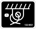
It is a violation of California Public Resource Code Section 4442 or 4443 to use or operate the engine on any forest-covered,
brush-covered, or grass-covered land unless the engine is equipped with a spark arrester, as defined in Section 4442, maintained
in effective working order or the engine is constructed, equipped, and maintained for the prevention of fire.
Because in some areas there are local, state, or federal regulations requiring that a spark arrester be used on the engine
of this machine, a spark arrester is available as an option. If you require a spark arrester, contact your Authorized Service
Dealer. Genuine Toro spark arresters are approved by the USDA Forestry Service.
The enclosed engine owner's manual is supplied for information regarding the US Environmental Protection Agency (EPA) and
the California Emission Control Regulation of emission systems, maintenance, and warranty. Replacements may be ordered through
the engine manufacturer.
 |
| |
| CALIFORNIA |
| |
| Proposition 65 |
| |
| The engine exhaust from this product contains chemicals known to
the State of California to cause cancer, birth defects, or other reproductive
harm. |
| |
| Battery posts, terminals, and related accessories contain lead and
lead compounds, chemicals known to the State of California to cause
cancer and reproductive harm. Wash hands after handling. |
| |
| Use of this product may cause exposure to chemicals known to the
State of California to cause cancer, birth defects, or other reproductive
harm. |
| |
Intended Use
This machine is intended to be used by professional, hired operators in commercial applications. This machine is a stable,
reliable, and productive machine for carrying and moving materials for any job site. It is primarily designed to move concrete,
mortar, gravel, dirt, or debris around job sites. Using this product for purposes other than its intended use could prove
dangerous to you and bystanders.
Read this information carefully to learn how to operate and maintain your product properly and to avoid injury and product
damage. You are responsible for operating the product properly and safely.
Getting Help
Visit www.Toro.com for product safety and operation training materials, accessory information, help finding a dealer, or to register your product.
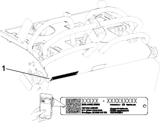
Whenever you need service, genuine Toro parts, or additional information, contact an Authorized Service Dealer or Toro Customer Service and have the model and serial numbers of your product ready. These numbers are located on the serial plate
on your product  . Write the numbers in the space provided.
With your mobile device, you can scan the QR code on the serial number decal (if equipped) to access warranty, parts, and
other product information.
|
Model Number:
|
|
Serial Number:
|
|
Manual Conventions
This manual identifies potential hazards and has safety messages identified by the safety-alert symbol, which signals a hazard
that may cause serious injury or death if you do not follow the recommended precautions.
This manual uses 2 words to highlight information. Important calls attention to special mechanical information and Note emphasizes general information worthy of special attention.
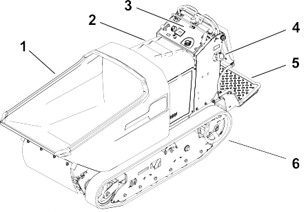
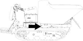
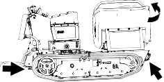
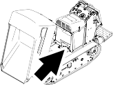
g038268
- Hopper
- Hood
- Control panel
- Fuel-tank cap
- Operator platform
- Tracks
Controls
Choke Control
G376191
- Engage the choke before starting a cold engine.
- Disengage the choke when the engine is warm.
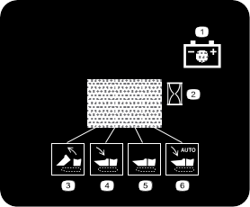
Dump Controls
G375675
- Dump hopper
- Lower hopper
Swivel Switch
G375676
- Swivel left
- Swivel right
Key Switch
G375755
- Stop engine
- Run engine
- Start engine
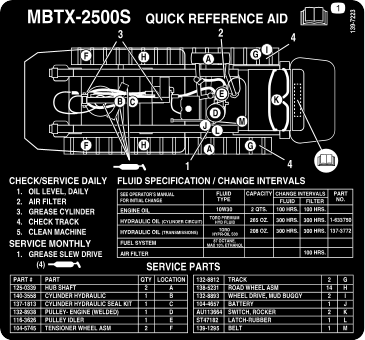
Specifications
Note: Specifications and design are subject to change without notice.
|
Width
|
90.2 cm (35.5 inches)
|
|
Length
|
268 cm (105.5 inches)
|
|
Height
|
130.18 cm (51.25 inches)
|
|
Weight
|
855.5 kg (1886 lb)
|
|
Hopper capacity
|
0.45 m3 (16 cu.ft.)
|
|
Maximum load
|
1134 kg (2500 lb)
|
|
Discharge height
|
38.1 cm (15 inches)
|
Attachments/Accessories
A selection of Toro approved attachments and accessories is available for use with the machine to enhance and expand its capabilities. Contact
your Authorized Service Dealer or authorized Toro distributor or go to www.Toro.com for a list of all approved attachments and accessories.
To ensure optimum performance and continued safety certification of the machine, use only genuine Toro replacement parts and accessories.
Note: Determine the left and right sides of the machine from the normal operating position.
Refer to your engine owner's manual for additional maintenance procedures.
Maintenance Safety
- Park the machine on a level surface, engage the parking brake, and shut off the engine. Wait for all movement to stop and
allow the machine to cool before adjusting, servicing, cleaning, or storing the machine.
- Disconnect the battery or remove the spark-plug wire before making any repairs. Disconnect the negative terminal first and
the positive terminal last. Connect the positive terminal first and negative last.
- Charge the batteries in an open, well-ventilated area, away from spark and flames. Unplug the charger before connecting or
disconnecting it from the battery. Wear protective clothing and use insulated tools.
- Battery acid is poisonous and can cause burns. Avoid contact with skin, eyes, and clothing. Protect your face, eyes, and clothing
when working with a battery.
- Battery gasses can explode. Keep cigarettes, sparks, and flames away from the battery.
- Do not change the engine governor setting or overspeed the engine.
- Support the machine with jack stands whenever you work under the machine.
- Carefully release pressure from components with stored energy.
- Keep all parts in good working condition and all hardware tightened. Replace all worn or damaged decals.
- Use the cylinder lock to secure the hopper in the raised position.
- Never tamper with safety devices.
- To ensure safe, optimal performance of the machine, use only genuine Toro replacement parts. Replacement parts made by other manufacturers could be dangerous, and such use could void the product
warranty.
- Seek immediate medical attention if fluid is injected into skin. Injected fluid must be surgically removed within a few hours
by a doctor.
- Ensure that all hydraulic-fluid hoses and lines are in good condition and all hydraulic connections and fittings are tight
before applying pressure to the hydraulic system. Keep your body and hands away from pinhole leaks or nozzles that eject high-pressure
hydraulic fluid.
- Use cardboard or paper to find hydraulic leaks.
- Safely relieve all pressure in the hydraulic system before performing any work on the hydraulic system.
Recommended Maintenance Schedule
|
Before each use or daily
|
|
- |
- |
- |
|
|
- |
- |
- |
|
|
- |
- |
- |
|
|
- |
- |
- |
|
|
- |
- |
- |
|
|
- |
- |
- |
|
Check for loose fasteners.
|
- |
- |
- |
|
|
- |
- |
- |
|
After the first 10 hours
|
|
- |
- |
- |
|
Every 25 hours
|
|
- |
- |
- |
|
Every 40 hours
|
|
- |
- |
- |
| |
| |
|
Every 50 hours
|
|
- |
- |
- |
|
|
- |
- |
- |
|
|
- |
- |
- |
|
Every 100 hours
|
|
- |
- |
- |
|
|
- |
- |
- |
|
|
- |
- |
- |
|
|
- |
- |
- |
|
|
- |
- |
- |
|
Clean the cooling areas under the cooling shrouds.
|
- |
- |
- |
|
|
- |
- |
- |
|
|
- |
- |
- |
|
Every 300 hours
|
|
- |
- |
- |
|
|
- |
- |
- |
|
|
139-1295 |
1 |
Belt |
|
|
108-1184 |
1 |
Toro premium transmission/hydraulic fluid |
|
|
114-4714 |
2 |
Toro hypr-oil 500 |
|
|
137-3772 |
2 |
Filter |
|
|
1-633750 |
1 |
Filter |
Pre-Maintenance Procedures
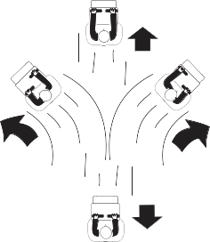
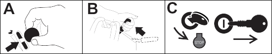
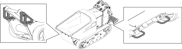
Moving a Non-Functional Machine
Do not tow or pull the machine without first opening the bypass valves in this procedure, or you will damage the hydraulic
system.
Note: Opening the bypass valves will ease moving the machine, but the tracks may still skid due to their length and resistance.
-
If possible, raise the hopper and install the cylinder lock.
-
Shut off the engine and remove the key.
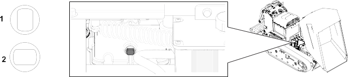
-
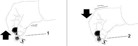
Using a wrench, turn the bypass valve on the left and right transaxles so that the flat sides of the valve face left and right
(Tow position ).
-
Tow the machine as required.
-
After repairing the machine, turn the bypass valves so that the flat sides face up and down (drive position  ).
).
-
Remove the cylinder lock and lower the hopper.
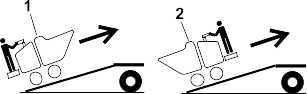
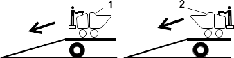
Lifting the Machine
Ensure that the hopper is empty before lifting the machine.
-
Place the platform in the raised position.
-
Rotate the hopper and hoist the machine using the lifting points.
Note: Take up the slack in the chain or straps to properly balance the unit.
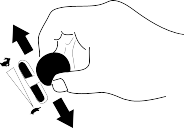
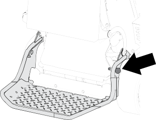
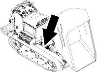
Releasing the Cushion for Rear Access
-
Lower the platform.
-
Loosen the twist knobs on each side of the machine.
-
Remove the cushion and lower it to the platform.
-
Perform any maintenance or adjustment on the machine.
-
Raise the cushion, and slide it onto the pins on both sides of the machine.
-
Tighten the twist knobs.
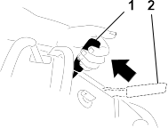
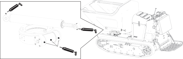
Using the Cylinder Lock
Installing the Cylinder Lock
-
Park the machine on a level surface, move the motion-control levers to the Neutral-lock position, engage the parking brake, and fully raise the hopper.
-
Remove the 2 cotterless pins securing the cylinder lock to the machine.
-
Slide the cylinder lock over the lift-cylinder rod and secure with the cotterless pins.
Removing and Storing the Cylinder Lock
Remove the cylinder lock from the lift-cylinder rod and fully secure it in the storage position before operating the machine.
-
Start the machine.
-
Fully raise the hopper.
-
Shut off the engine.
-
Remove the cotterless pins securing the cylinder lock.
-
Place the cylinder lock on the posts inside the machine frame and secure with the cotterless pins.
-
Lower the hopper.
Lubrication
Greasing the Machine
Grease Type: General-purpose grease.
Note: Remove the blue protection caps, if applicable, before greasing and replace when finished.
-
Park the machine on a level surface and engage the parking brake.
-
Shut off the engine and allow the engine to cool.
-
Clean the grease fittings with a rag.
-
Connect a grease gun to each fitting.
-
Pump grease into the fittings until grease begins to ooze out of the bearings (approximately 3 pumps).
-
Wipe up any excess grease.
Engine Maintenance
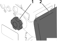
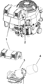
Servicing the Air Cleaner
Do not operate the engine without the air-cleaner element. Operating without an element causes damage to the engine.
-
Rotate the latches outward.
-
Remove the cover to access the air-cleaner elements.
-
Remove the cover to access the air-cleaner elements.
-
Remove the foam element  from the paper element
  .
.
-
Service the foam element .
-
Wash the foam element in warm water and detergent.
-
Rinse it and allow it to air dry.
-
Lightly oil the foam element with new oil and squeeze out excess oil.
-
Service the paper element .
-
Gently tap the paper element to dislodge dirt.
Note: Do not wash the paper element or use pressurized air, as this damages the element.
Note: Replace a dirty, bent, or damaged element. Handle the new element carefully; do not use if the sealing surfaces are bent or
damaged.
-
Install the elements.
-
Install the foam element onto the paper element.
-
Install the elements onto the air-cleaner base.
-
Install the cover, and secure it with the latches.
Engine Oil Service
Engine Oil Specifications
|
Crankcase capacity:
|
1.9 L (64 fl oz)
|
|
Oil type:
|
API classification SJ or later.
|
|
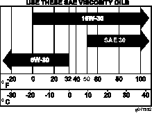
Oil viscosity:
|
Selected the oil viscosity according to ambient temperature in the table below.
|
Checking the Engine-Oil Level
-
Park the machine on a level surface, move the motion-control levers to the Neutral-lock position, engage the parking brake, and lower the hopper.
-
Shut off the engine, and remove the key. Allow the engine to cool.
-
Open the cowl.
-
Check the engine-oil level.
Changing the Engine Oil and Filter
-
Park the machine on a level surface, move the motion-control levers to the Neutral-lock position, engage the parking brake, raise the hopper, and install the cylinder lock.
-
Shut off the engine and remove the key.
-
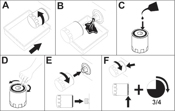
Perform the following steps to change the engine oil:
-
Remove the drain plug and allow all of the existing oil to drain out of the engine.
-
Install the drain plug. Torque the plug to 13.6 N∙m (10 ft-lb).
-
Change the engine-oil filter.
-
Slowly pour approximately 80% of the specified oil into the filler tube.
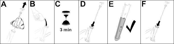
Replacing the Spark Plug
-
Remove the spark-plug wire.
-
Clean around spark plug and remove plug from cylinder head.
Note: Replace a cracked, fouled, or dirty spark plug. Do not sand blast, scrape, or clean electrodes because engine damaged could
result from grit entering the cylinder.
-
Set the air gap at 0.70 to 0.80 mm (0.028 to 0.031 inch) . Install the spark plug carefully by hand to avoid cross-threading.
-
After the spark plug is seated, tighten it with a spark plug wrench to compress the sealing washer.
-
When installing a new spark plug, tighten 1/2 turn after the spark plug seats to compress the washer.
-
When installing the original spark plug, tighten 1/8 to 1/4 turn after the spark plug seats to compress the washer.
Note: A loose spark plug can overheat and damage the engine. Overtightening the spark plug can damage the threads in the cylinder
head.
-
Connect the spark-plug wire.
Cleaning the Blower Housing
To ensure proper cooling, ensure that the cooling fins and other external surfaces of the engine are kept clean at all times.
Ensure that the cooling shrouds are installed.
Operating the engine with dirty or plugged cooling fins and/or cooling shrouds removed causes engine damage due to overheating.
-
Fuel System Maintenance
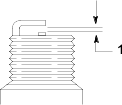
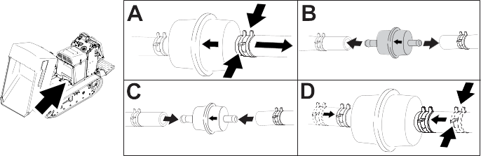
Replacing the Fuel Filter
-
Park the machine on a level surface, move the motion-control levers to the Neutral-lock position, engage the parking brake, and lower the hopper.
-
Shut off the engine, and remove the key. Allow the engine to cool.
-
Replace the fuel filter.
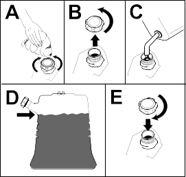
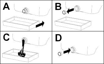
Draining the Fuel Tank
You can drain the fuel tank by either siphoning the fuel out or removing the fuel tank and pouring the fuel out of the fill
neck.
-
Park the machine on a level surface, move the motion-control levers to the Neutral-lock position, engage the parking brake, and lower the hopper.
-
Shut off the engine, and remove the key. Allow the engine to cool.
-
Clean around the fuel cap to prevent debris from getting into the fuel tank.
-
Remove the fuel cap.
-
Insert a syphon pump into the fuel tank.
-
Using the syphon pump, drain the fuel into a clean fuel can.
-
Wipe up any spilled fuel.
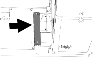
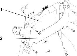
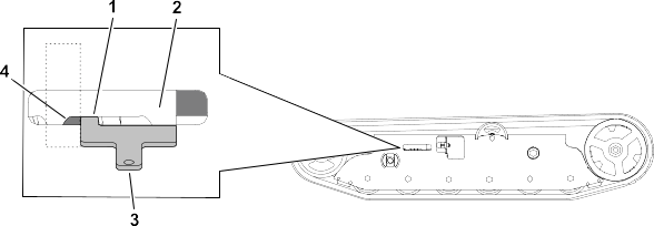
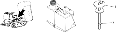
Removing the Fuel Tank
-
Lower the platform.
-
Release the cushion.
-
Remove the cross bracket .
-
Remove the fuel tank and set it on the operator platform.
Note: Remove the fuel and vent lines from the top of the tank to move the fuel tank further from the machine.
Electrical System Maintenance
Electrical System Safety
- Disconnect the battery before repairing the machine. Disconnect the negative terminal first and the positive last. Connect
the positive terminal first and the negative last.
- Charge the battery in an open, well-ventilated area, away from sparks and flames. Unplug the charger before connecting or
disconnecting the battery. Wear protective clothing and use insulated tools.
- Battery acid is poisonous and can cause burns. Avoid contact with skin, eyes, and clothing. Protect your face, eyes, and clothing
when working with a battery.
- Battery gases can explode. Keep cigarettes, sparks, and flames away from the battery.
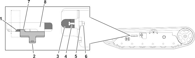
Battery Service
Removing the Battery
-
Park the machine on a level surface, move the motion-control levers to the Neutral-lock position, engage the parking brake, and lower the hopper.
-
Shut off the engine, and remove the key. Allow the engine to cool.
-
Remove the negative battery cable from the battery.
-
Remove the positive battery cable from the battery.
-
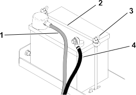
Remove the 2 wing nuts , securing rod , and the battery.
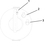
Charging the Battery
 |
Warning |
|
Charging the battery produces gasses that can explode.
Never smoke near the battery and keep sparks and flames away from battery.
Always keep the battery fully charged (1.265 specific gravity). This is especially important to prevent battery damage when
the temperature is below 0°C (32°F).
-
Remove the battery from the machine.
-
Perform the following steps to check the electrolyte level:
-
Ensure that the cell covers are free from dirt and debris.
Dirt and debris that enters the battery cells causes damage to the battery.
-
Remove the covers from the top of the cells.
-
Ensure that the electrolyte solution covers the lead plates. Use distilled water to top off the solution level, if needed.
-
Ensure that the filler caps are installed on the battery.
-
Charge the battery for 1 hour at 25 to 30 A or 6 hours at 4 to 6 A.
Do not overcharge the battery.
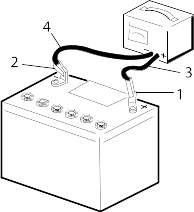
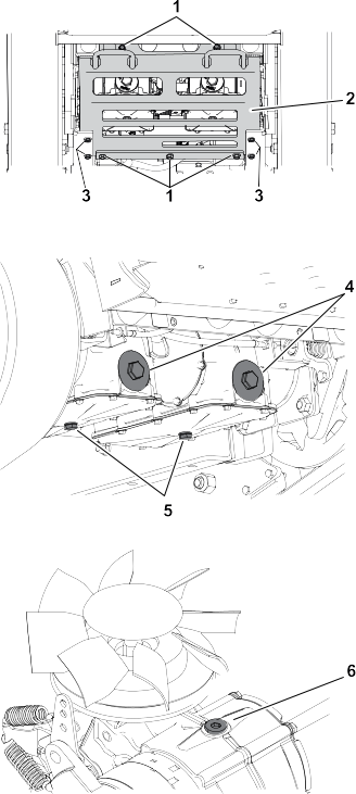
g003792
- Positive battery post
- Negative battery post
- Red (+) charger lead
- Black (-) charger lead
-
When the battery is fully charged, unplug the charger from the electrical outlet, and disconnect the charger leads from the
battery posts.
-
Install the battery onto the machine and connect the battery cables.
Note: Do not run the machine with the battery disconnected; electrical damage may occur.
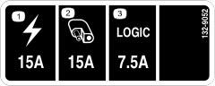
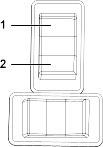
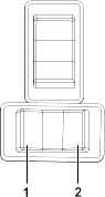
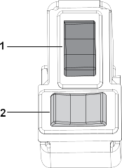
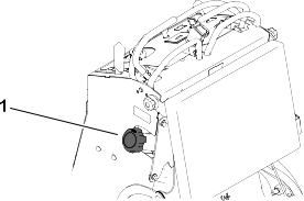
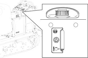
Replacing a Fuse
The electrical system is protected by fuses and requires no maintenance. If a fuse blows, check the component or circuit for
a malfunction or short.
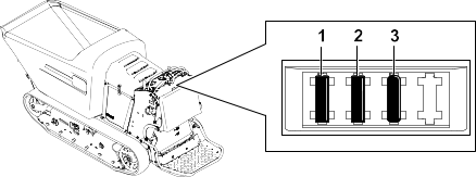
G376375
- Main power fuse (15 A)
- Auxiliary power fuse (15 A)
- Logic fuse (7.5 A)
-
Release the cushion from the rear of the machine.
-
Pull out the fuse to remove or replace it.
-
Install the cushion to the rear of the machine.
Note: Ensure that the correct-size fuse is installed.
If a fuse blows a second time, check the component/circuit for a malfunction or a short or contact your Authorized Service
Dealer.
Drive System Maintenance
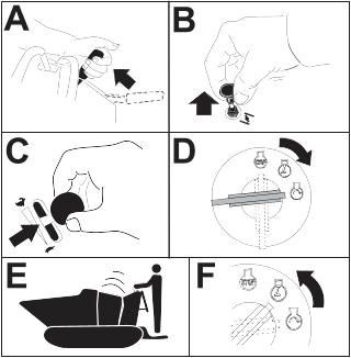
Track Service
Cleaning the Tracks
-
Park the machine on a level surface, move the motion-control levers to the Neutral-lock position, engage the parking brake, and lower the hopper.
-
Shut off the engine, and remove the key. Allow the engine to cool.
-
Lift/support the side of the machine to be worked on so that the track is 7.6 to 10 cm (3 to 4 inches) off the ground.
-
Using a water hose or pressure washer, remove dirt from each track system.
Ensure that you use high-pressure water to wash only the track area. Do not use a high-pressure washer to clean the rest of
the machine. Do not use high-pressure water between the drive sprocket and the machine or you may damage the motor seals.
High-pressure washing can damage the electrical system and hydraulic valves or deplete grease.
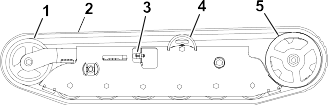
Ensure that you fully clean the road wheels, the front wheel, and the drive sprocket. The road wheels should rotate freely
when clean.
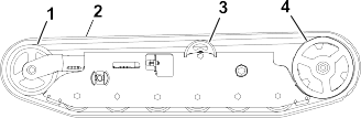
G186007
- Front wheel
- Track
- Road wheel
- Drive sprocket
Adjusting the Track Tension
-
Park the machine on a level surface, move the motion-control levers to the Neutral-lock position, engage the parking brake, and lower the hopper.
-
Shut off the engine, and remove the key. Allow the engine to cool.
-
Clean the tracks with high-pressure water.
Ensure that you use high-pressure water to wash only the track area. Do not use a high-pressure washer to clean the rest of
the machine. Do not use high pressure water between the drive sprocket and the machine or you may damage the motor seals.
High-pressure washing can damage the electrical system and hydraulic valves or deplete grease.
-
Raise the machine so that the tracks are off the ground.
-
Clean the drive sprocket, the front wheel, and the road wheels. The road wheels should spin freely when clean.
-
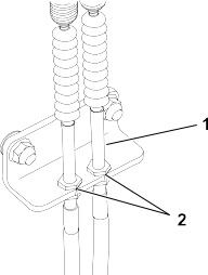
Remove the bolt (1/4 x 1-5/8 inches) , spacer  , and nut
  .
.
-
Turn the tensioning bolt to adjust the distance between the tension nut and the end tangent of the tension tube until the distance is correct.
-
Align the closest notch in the tensioning bolt to the bolt hole and secure the tensioning bolt with the bolt (1/4 x 1-5/8
inches), spacer, and nut.
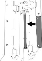
Replacing the Tracks
Removing a Track
-
Park the machine on a level surface, move the motion-control levers to the Neutral-lock position, engage the parking brake, and lower the hopper.
-
Shut off the engine, and remove the key. Allow the engine to cool.
-
Lift/support the side of the machine to be worked on so that the track is 7.6 to 10 cm (3 to 4 inches) off the ground.
-
Remove the retaining bolt for the tensioning screw.
g186008
- Front wheel
- Track
- Tensioning screw and retaining bolt
- Road wheel
- Drive sprocket
-
Release the drive tension by turning the tensioning screw clockwise.
-
Remove the track at the top of the front wheel, peeling it off the wheel while rotating the track forward.
-
When the track is off the front wheel, remove it from the drive sprocket and road wheels.
-
Inspect the condition of the wheels. If the wheels show signs of wear, replace them at this time.
Installing a Track
-
Park the machine on a level surface, move the motion-control levers to the Neutral-lock position, engage the parking brake, and lower the hopper.
-
Shut off the engine, and remove the key. Allow the engine to cool.
-
Lift/support the side of the machine to be worked on.
g186008
- Front wheel
- Track
- Tensioning screw and retaining bolt
- Road wheel
- Drive sprocket
-
Beginning at the drive sprocket, coil the new track around the sprocket, ensuring that the lugs on the track fit between the
spacers on the sprocket.
-
Push the track under the lugs and between the road wheels.
-
Starting at the bottom of the front wheel, install the track around the wheel by rotating the track rearward while pushing
the lugs into the wheel.
-
Tension the track.
-
Lower the machine to the ground.
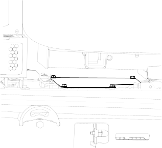
Drive Belt
Inspecting the Drive Belt
-
Park the machine on a level surface, move the motion-control levers to the Neutral-lock position, engage the parking brake, and lower the hopper.
-
Shut off the engine, and remove the key. Allow the engine to cool.
-
Release the cushion and remove the fuel tank.
-
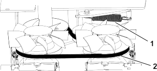
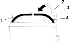
Inspect the belt. Replace the belt if it is worn.
Note: The signs of a worn belt include squealing while the belt is rotating, frayed edges, burn marks, and cracks on the belt.
G189546
- Extension spring
- Belt
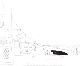
Replacing the Drive Belt
-
Park the machine on a level surface, move the motion-control levers to the Neutral-lock position, engage the parking brake, and lower the hopper.
-
Shut off the engine, and remove the key. Allow the engine to cool.
-
Release the cushion and remove the fuel tank.
-
Raise the rear of the machine and support the machine on jack stands.
-
Remove the skid plate.
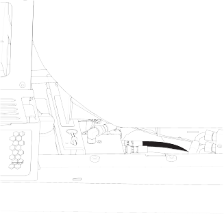
G325648
- Rear bolt (2)
- Skid plate
- Side bolt (4)
-
Remove the extension spring.
-
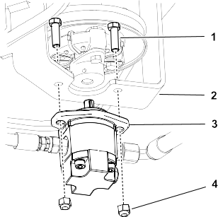
Remove the 2 bolts and 2 nuts and loosen the 2 set screws on the coupler. Remove the gear pump from the pump mount.
Note: You do not need to remove the fittings from the pump.
G189559
- Bolt (2)
- Pump mount
- Gear pump
- Nut (2)
-
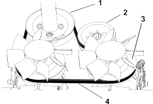
Remove the drive belt from the engine pulley and 2 transmission pulleys.
G189571
- Engine pulley
- Idler pulley
- Transmission pulley (2)
- Belt
-
Route the new belt around the engine pulley and 2 transmission pulleys.
-
Install the gear pump.
-
Install the extension spring.
-
Install the fuel tank.
-
Raise the cushion.
Controls Maintenance
Adjusting the Motion-Control Levers
If the motion-control levers do not align horizontally, adjust the right side motion-control lever.
-
Park the machine on a level surface, lower the hopper, engage the parking brake, shut off the engine, and remove the key.
-
Push the motion-control levers down out of the Neutral-lock position.
-
Check if the right motion-control lever aligns horizontally with the left motion-control lever.
G009436
- Left motion-control lever
- Right motion-control lever in the Neutral-lock position
- Check the horizontal alignment here
- Right motion-control lever
-
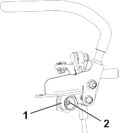
Release the cushion from the rear of the machine.
-
Loosen the nut holding the cam .
-
Adjust the cam until it aligns with the left motion-control lever and tighten the nut for the cam.
Note: Moving the cam clockwise (in the vertical position) lowers the handle; moving the cam counterclockwise (in the vertical position)
raises the handle.
Ensure that the flat portion of the cam does not go above a vertical position (right or left); otherwise you may damage the
switch.
-
Repeat Step through Step for the left motion-control lever.
Brake Maintenance
Checking the Parking Brake
-
Park the machine on a level surface, lower the hopper, and engage the parking brake.
-
Start the engine and move the throttle lever to the Fast position.
-
Move the motion-control levers forward.
The machine should not move forward.
If the machine moves forward, adjust the parking brake.
-
Release the parking brake.
-
Move the motion-control levers forward.
The machine should move forward.
If the machine does not move forward, adjust the parking brake.
-
Engage the parking brake and shut off the machine.
Adjusting the Parking Brake
-
Remove the fuel tank.
-
Inside the left side of the control tower, adjust the nuts until the cables are taught.
-
Install the fuel tank, cross bracket, and cushion.
Hydraulic System Maintenance
Hydraulic Drive System
Hydraulic Drive System Fluid Specifications
|
Hydraulic-Fluid type:
|
Toro® HYPR-OIL™ 500
|
|
Hydraulic fluid capacity:
|
1.4 L (1.5 US qt)
|
Use only 1 of the following fluids in the hydraulic system:
- Toro Premium Transmission/Hydraulic Tractor Fluid (refer to your Authorized Service Dealer for more information)
- Toro PX Extended Life Hydraulic Fluid (refer to your Authorized Service Dealer for more information)
- If either of the above Toro fluids are not available, you may use another Universal Tractor Hydraulic Fluid (UTHF), but they must be only conventional, petroleum-based products. The specifications must fall within the listed range for all the following material properties and the fluid should
meet the listed industry standards. Check with your hydraulic fluid supplier to determine if the fluid meets these specifications.
Note: Toro will not assume responsibility for damage caused by improper substitutions, so use only products from reputable manufacturers
who will stand behind their recommendations.
| Material Properties |
| Viscosity, ASTM D445 |
cSt at 40°C: 55 to 62 |
| cSt at 100°C: 9.1 to 9.8 |
| Viscosity index, ASTM D2270 |
140 to 152 |
| Pour Point, ASTM D97 |
-37 to -43°C (-35 to -46°F) |
| Industry Standards |
| API GL-4, AGCO Powerfluid 821 XL, Ford New Holland FNHA-2-C-201.00, Kubota UDT, John Deere J20C, Vickers 35VQ25 and Volvo
WB-101/BM |
Note: Many hydraulic fluids are almost colorless, making it difficult to spot leaks. A red dye additive for the hydraulic system
fluid is available in 20 ml (2/3 fl oz) bottles. One bottle is sufficient for 15 to 22 L (4 to 6 US gallons) of hydraulic
fluid. Order Part No. 44-2500 from your Authorized Toro Dealer.
Checking the Hydraulic-Fluid Level for the Drive System
-
Park the machine on a level surface, move the motion-control levers to the Neutral-lock position, engage the parking brake, and lower the hopper.
-
Shut off the engine, and remove the key. Allow the engine to cool.
-
Open the cowl.
-
Use the sight window to check the fluid level in the expansion tank.
Note: The fluid level should be at the fill line on the decal.
-
If the oil level is low, remove the cap lock and cap from the top of the expansion tank and add enough of the specified hydraulic fluid to raise it to the proper level.
Note: Ensure that the expansion-tank fluid level is at the proper level. Overfilling the tank may cause fluid to purge out of the
breather hole.
-
Install the cap and cap lock. Wipe up any spilled hydraulic fluid.
Changing the Hydraulic Fluid and Filter for the Drive System
-
Park the machine on a level surface, move the motion-control levers to the Neutral-lock position, engage the parking brake, and lower the hopper.
-
Shut off the engine, and remove the key. Allow the engine to cool.
-
Lower the cushion and remove the fuel tank.
-
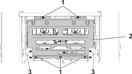
Remove the 9 bolts (5 rear , 4 side ) from the skid plate and remove the skid plate.
-
Locate the drain plug in the bottom of each transmission, then place a drain pan under the plugs.
-
Remove the drain plugs and allow the hydraulic fluid to fully drain from the machine.
-
Remove the hydraulic-filter cap and hydraulic filter from each transmission.
-
Install a new hydraulic filter with the spring side facing out and the hydraulic-filter cap for each transmission.
-
Torque to 13 to 15 N∙m (115 to 135 in-lb).
-
Install the drain plugs.
-
Loosen the vent plug in each transmission until loose.
Note: This allows air to escape the hydraulic system as you add hydraulic fluid.
-
Slowly add approximately 6.2 L (208 fl oz) fluid to the expansion tank until it starts to come out of the vent plugs.
Use the fluid specified or equivalent. Other fluids could cause system damage.
Monitor the level of fluid in the expansion tank so that you do not overfill it.
-
Tighten the vent plugs.
-
Add hydraulic fluid to the expansion tank until it reaches the fluid line.
-
Install the expansion-tank cap.
-
Install the skid plate.
-
Install the fuel tank.
-
Start the engine and let it run for about 2 minutes to purge air from the system.
-
Shut off the engine and check for leaks.
Bleeding the Hydraulic Drive System
Bleed the traction hydraulic system whenever you perform service or maintenance on the hydrostatic transmission or add hydraulic
fluid to the expansion tank.
-
Park the machine on a level surface, move the motion-control levers to the Neutral-lock position, engage the parking brake, and lower the hopper.
-
Shut off the engine, and remove the key. Allow the engine to cool.
-
Check the hydraulic fluid level and add hydraulic fluid as necessary.
-
Support the machine on jack stands, high enough to raise the tracks off the ground.
-
Start the machine. Slowly move the motion-control levers forward and reverse 5 to 6 times.
-
Check the hydraulic fluid level and add hydraulic fluid as necessary.
-
Repeat Step and Step as necessary until all the air is completely purged from the system.
Note: Purging is complete when you obtain normal forward and reverse speed.
-
Lower the machine and repeat the procedure with the tracks on the ground.
Hydraulic Lift and Slew System
Hydraulic Lift and Slew System Fluid Specifications
|
Hydraulic-Fluid type:
|
Toro Premium All Season Hydraulic Fluid or Mobil® 424 Hydraulic Fluid
|
|
Hydraulic fluid capacity:
|
6.6 L (1.75 US gallons)
|
Use only 1 of the following fluids in the hydraulic system:
- Toro Premium Transmission/Hydraulic Tractor Fluid (refer to your Authorized Service Dealer for more information)
- Toro PX Extended Life Hydraulic Fluid (refer to your Authorized Service Dealer for more information)
- If either of the above Toro fluids are not available, you may use another Universal Tractor Hydraulic Fluid (UTHF), but they must be only conventional, petroleum-based products. The specifications must fall within the listed range for all the following material properties and the fluid should
meet the listed industry standards. Check with your hydraulic fluid supplier to determine if the fluid meets these specifications.
Note: Toro will not assume responsibility for damage caused by improper substitutions, so use only products from reputable manufacturers
who will stand behind their recommendations.
| Material Properties |
| Viscosity, ASTM D445 |
cSt at 40°C: 55 to 62 |
| cSt at 100°C: 9.1 to 9.8 |
| Viscosity index, ASTM D2270 |
140 to 152 |
| Pour Point, ASTM D97 |
-37 to -43°C (-35 to -46°F) |
| Industry Standards |
| API GL-4, AGCO Powerfluid 821 XL, Ford New Holland FNHA-2-C-201.00, Kubota UDT, John Deere J20C, Vickers 35VQ25 and Volvo
WB-101/BM |
Note: Many hydraulic fluids are almost colorless, making it difficult to spot leaks. A red dye additive for the hydraulic system
fluid is available in 20 ml (2/3 fl oz) bottles. One bottle is sufficient for 15 to 22 L (4 to 6 US gallons) of hydraulic
fluid. Order Part No. 44-2500 from your Authorized Toro Dealer.
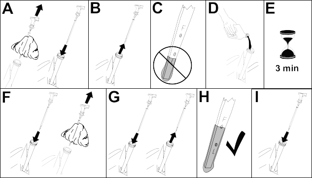
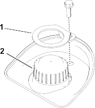
Checking the Hydraulic-Fluid Level for the Lift and Slew System
-
Park the machine on a level surface, move the motion-control levers to the Neutral-Lock position, engage the parking brake, rotate and raise the hopper, and install the cylinder lock.
-
Shut off the machine and remove the key. Allow the machine to cool completely.
-
Remove the filler cap from the reservoir tank.
-
Remove the dipstick from the filler neck and wipe it with a clean rag. Insert the dipstick into the filler neck; then remove it and check the
level of the fluid. The fluid level should be up to the full mark on the dipstick.
-
If the level is low, add the specified hydraulic fluid to raise the level to the full mark.
-
Install the dipstick and cap onto the filler neck.
-
Wipe up any spilled hydraulic fluid.
-
Remove the cylinder lock and lower the hopper.
Changing the Hydraulic Fluid for the Lift and Slew System
-
Park the machine on a level surface, move the motion-control levers to the NEUTRAL-LOCK position, engage the parking brake,
raise the hopper, and install the cylinder lock.
-
Shut off the machine and remove the key. Allow the machine to cool completely.
-
Remove the filler cap from the reservoir tank
-
Place a large drain pan under the fittings at the bottom of the reservoir tank.
-
Disconnect a hose fitting and allow the fluid to drain into the pan.
-
When finished, install and tighten the fitting. Note: Dispose of the used fluid at a certified recycling center.
-
Fill the reservoir tank with approximately 5.9 L (200 fl oz) and install the filler cap.
-
Remove the cylinder lock.
-
Start the engine. Raise and lower the hopper 3 times to fill the cylinder and hoses with fluid.
-
Raise the hopper and install the cylinder lock.
-
Shut off the engine.
-
Add 0.73 L (25 fl oz) of hydraulic fluid and install the filler cap.
Note: The fluid level should be at the Cold fill line. Do not fill past this line.
-
Remove the cylinder lock.
-
Start the engine. Raise and lower the hopper several times to remove air from the system.
Replacing the Hydraulic Filter for the Lift and Slew System
Do not substitute an automotive oil filter or severe hydraulic system damage may result.
-
Park the machine on a level surface, move the motion-control levers to the Neutral-lock position, engage the parking brake, raise the hopper, and install the cylinder lock.
-
Shut off the engine, and remove the key. Allow the engine to cool.
-
Replace the filter.
-
Start the engine and let it run for about 2 minutes to purge air from the system.
-
Shut off the engine and check for leaks.
-
Check the fluid level in the reservoir tank.
Note: Do not overfill the reservoir tank.
-
Remove the cylinder lock and lower the hopper.
Checking the Hydraulic Lines
-
Check the hydraulic lines for leaks, loose fittings, kinked lines, loose mounting supports, wear, and deterioration. Make
necessary repairs before operating.
Cleaning
Removing Debris
Operating the engine with blocked screens, dirty or plugged cooling fins, and/or cooling shrouds removed, will result in engine
damage from overheating.
-
Park the machine on a level surface and shut off the engine. Allow the engine to cool.
-
Unlatch and remove the cowl.
-
Clean any debris from under the hopper.
-
Wipe away debris from the air cleaner.
-
Clean any debris buildup on the engine and in the transmission with a brush or blower.
It is preferable to blow dirt out rather than washing it out. If you use water, keep it away from electrical items and hydraulic
valves.
Do not use a high-pressure washer. High-pressure washing can damage the electrical system and hydraulic valves or deplete
grease.
The engine loses power.
|
Possible Cause
|
Corrective Action
|
|
The engine load is excessive.
|
-
Reduce the ground speed.
|
|
The air cleaner is dirty.
|
-
Service the air-cleaner element.
|
|
The oil level in the crankcase is low.
|
-
Add oil to the crankcase.
|
|
The cooling fins and air passages under the engine blower housing are plugged.
|
-
Remove the obstruction from the cooling fins and air passages.
|
|
A spark plug is pitted, fouled, or the gap is incorrect.
|
-
Install a new, correctly gapped spark plug.
|
|
The vent hole in the fuel cap is plugged.
|
-
Clean or replace the fuel cap.
|
|
Dirt is in the fuel filter.
|
-
Replace the fuel filter.
|
|
Dirt, water, or stale fuel is in the fuel system.
|
-
Contact an Authorized Service Dealer.
|
The engine does not start, starts hard, or fails to keep running.
|
Possible Cause
|
Corrective Action
|
|
The fuel tank is empty or the shutoff valve is closed.
|
-
Fill the fuel tank with fuel and open the valve
|
|
A spark-plug wire is loose or disconnected.
|
-
Install the wire on spark plug.
|
|
A spark plug is pitted, fouled, or the gap is incorrect.
|
-
Install a new, correctly gapped spark plug.
|
|
The air cleaner is dirty.
|
-
Service the air-cleaner element.
|
|
Dirt is in the fuel filter.
|
-
Replace the fuel filter.
|
|
Dirt, water, or stale fuel is in the fuel system.
|
-
Contact an Authorized Service Dealer.
|
The engine overheats.
|
Possible Cause
|
Corrective Action
|
|
The engine load is excessive.
|
-
Reduce the ground speed.
|
|
The oil level in the crankcase is low.
|
-
Add oil to the crankcase.
|
|
The cooling fins and air passages under the engine blower housing are plugged.
|
-
Remove the obstruction from the cooling fins and air passages.
|
The machine does not drive.
|
Possible Cause
|
Corrective Action
|
|
The hydraulic-fluid in the transmission is low.
|
-
Add hydraulic fluid to the hydraulic fluid expansion tank in the tower.
|
|
Air is in the hydraulic system.
|
-
Bleed the air out the hydraulic system.
|
|
A drive belt slipped.
|
-
Replace the pump-drive belt.
|
|
A drive belt idler spring is missing.
|
-
Replace the pump-drive belt idler spring.
|
|
The bypass valves are in the tow position.
|
-
Turn the bypass valves to the drive position.
|
California Proposition 65 Warning Information
What is this warning?
You may see a product for sale that has a warning label like the following:
 |
WARNING: Cancer and Reproductive Harm—www.p65Warnings.ca.gov. |
What is Prop 65?
Prop 65 applies to any company operating in California, selling products in California, or manufacturing products that may
be sold in or brought into California. It mandates that the Governor of California maintain and publish a list of chemicals
known to cause cancer, birth defects, and/or other reproductive harm. The list, which is updated annually, includes hundreds
of chemicals found in many everyday items. The purpose of Prop 65 is to inform the public about exposure to these chemicals.
Prop 65 does not ban the sale of products containing these chemicals but instead requires warnings on any product, product
packaging, or literature with the product. Moreover, a Prop 65 warning does not mean that a product is in violation of any
product safety standards or requirements. In fact, the California government has clarified that a Prop 65 warning “is not the same as a regulatory decision that a product is ‘safe’ or ‘unsafe.’” Many of these chemicals have been used in everyday products for years without documented harm. For more information, go to
https://oag.ca.gov/prop65/faqs-view-all.
A Prop 65 warning means that a company has either (1) evaluated the exposure and has concluded that it exceeds the “no significant risk level”; or (2) has chosen to provide a warning based on its understanding about the presence of a listed chemical without attempting
to evaluate the exposure.
Does this law apply everywhere?
Prop 65 warnings are required under California law only. These warnings are seen throughout California in a wide range of
settings, including but not limited to restaurants, grocery stores, hotels, schools, and hospitals, and on a wide variety
of products. Additionally, some online and mail order retailers provide Prop 65 warnings on their websites or in catalogs.
How do the California warnings compare to federal limits?
Prop 65 standards are often more stringent than federal and international standards. There are various substances that require
a Prop 65 warning at levels that are far lower than federal action limits. For example, the Prop 65 standard for warnings
for lead is 0.5 μg/day, which is well below the federal and international standards.
Why don’t all similar products carry the warning?
- Products sold in California require Prop 65 labelling while similar products sold elsewhere do not.
- A company involved in a Prop 65 lawsuit reaching a settlement may be required to use Prop 65 warnings for its products, but
other companies making similar products may have no such requirement.
- The enforcement of Prop 65 is inconsistent.
- Companies may elect not to provide warnings because they conclude that they are not required to do so under Prop 65; a lack
of warnings for a product does not mean that the product is free of listed chemicals at similar levels.
Why does Toro include this warning?
Toro has chosen to provide consumers with as much information as possible so that they can make informed decisions about the products
they buy and use. Toro provides warnings in certain cases based on its knowledge of the presence of one or more listed chemicals without evaluating
the level of exposure, as not all the listed chemicals provide exposure limit requirements. While the exposure from Toro products may be negligible or well within the “no significant risk” range, out of an abundance of caution, Toro has elected to provide the Prop 65 warnings. Moreover, if Toro does not provide these warnings, it could be sued by the State of California or by private parties seeking to enforce Prop
65 and subject to substantial penalties.