Note: Determine the left and right sides of the machine from the normal operating position.
Installation
Preparing the Machine
-
Park the machine on a level surface.
-
Engage the parking brake.
-
Lower the loader arms.
-
Shut off the engine, remove the key, and allow the machine to cool.
-
Open the rear-access cover and engine hood.
-
Turn the battery-disconnect switch to the OFF position.
-
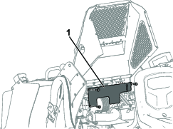
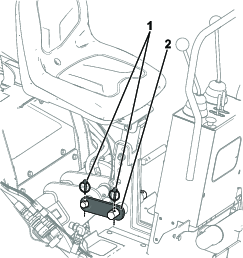
Remove the cover plate by removing the 3 bolts holding it in place (Figure 1).
Note: Retain the cover plate and corresponding bolts for later installation.
Replacing the Tilt-Cylinder Pin
Parts needed for this procedure:
| Tilt-cylinder pin | 1 |
-
Tilt the traction unit attachment mount plate flat and gently rest the attachment mount plate on top of a block.
-
Place a block in front of the mount plate so that it cannot swing forward when you remove the tilt-cylinder pin.
Caution
When you remove the tilt-cylinder pin, the mount plate may swing forward, crushing your feet or hands, or those of bystanders.
Place a block in front of the mount plate before removing the tilt-cylinder pin.
-
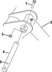
Remove the bolt and nut securing the upper tilt-cylinder pin on the traction unit (Figure 2).
-
Using a hammer and punch, remove the tilt-cylinder pin.
-
Install the new pin into position and secure it with the bolt and nut removed previously, using the middle hole on the pin (Figure 2).
-
Grease the pin using the fitting on the tilt cylinder.
Note: Leave the new pin installed, even when the backhoe is removed.
Installing the Quick-Attach Plate and Tie-Down Links
Parts needed for this procedure:
| Quick-attach plate | 1 |
| Small bolt | 2 |
| Large bolt | 8 |
| Small washer | 4 |
| Large washer | 24 |
| Spacer | 8 |
| Nut | 10 |
| Tie-down link | 2 |
| Pin lock | 4 |
-
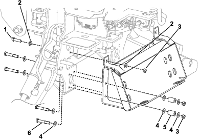
Install the quick-attach plate onto the backhoe using 2 small bolts, 4 small washers, 8 large bolts, 24 large washers, 8 spacers, and 10 nuts (Figure 3). Torque the bolts to 94 to 102 Nꞏm (70 to 75 ft-lb).
-
Connect the traction unit receiver plate to the backhoe quick-attach plate and engage the quick-attach pins; refer to the traction unit Operator’s Manual.
-
Install a tie-down link as shown in Figure 4. Secure the tie-down link with 2 pin locks.
-
Repeat step 3 on the other side of the machine.
-
Connect the hydraulic hoses; refer to the traction unit Operator’s Manual.
Installing the Wire Harness
Parts needed for this procedure:
| Jumper wire (for use on traction units with serial number 3999999999 and below only) | 2 |
| Fit-up kit electrical harness | 1 |
| Electrical harness cap | 1 |
| Cable tie | 4 |
Note: Use the jumper wires on traction units with serial number 3999999999 and below only.
-
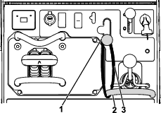
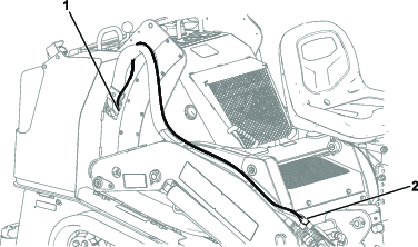
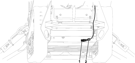
Plug the fit-up kit harness connector into the backhoe electrical harness connector (Figure 5).
Note: When you are not using the backhoe, ensure to install the electrical harness cap on the backhoe end of the fit-up kit harness.
-
Route the fit-up kit electrical harness alongside the hydraulic hoses as shown in Figure 5.
-
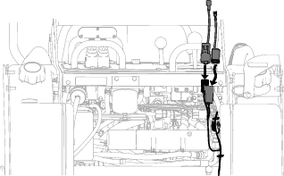
Route the harness through the hydraulic hose access hole into the underside of the control panel (Figure 5).
Note: Use the hydraulic hose tie downs to secure the harness.
-
Open the rear-access cover.
-
For traction units with serial numbers 3999999999 and below:
-
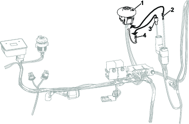
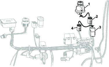
Plug the 2 jumper wires into the corresponding fit-up kit harness connectors (Figure 6).
-
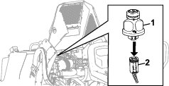
Under the control panel, remove the traction unit harness terminal from the ignition switch (Figure 7).
-
Plug the traction unit harness ignition terminal into the corresponding jumper terminal (Figure 8).
-
Plug the other jumper terminal into the ignition switch (Figure 8).
For traction units with serial numbers 4000000000 and up:
-
-
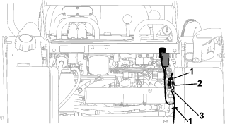
Below the ignition switch, under the hood, connect the 2 light kit connections (Figure 11).
-
Secure the harness to the traction unit wire harness with 2 cable ties as shown in Figure 11.
-
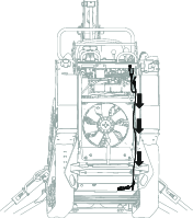
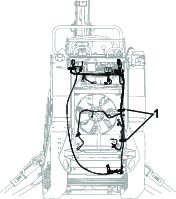
Route the rest of the harness down the inside of the traction unit frame alongside the traction unit wire harness as shown in Figure 12.
-
Lift the back of the machine off the ground. Support the machine using jack stands.
Note: Use jack stands rated for your machine.
Warning
Mechanical or hydraulic jacks may fail to support the machine and cause serious injury.
Use jack stands when supporting the machine.
-
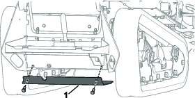
Remove the bottom cover from the traction unit by removing the 2 bolts holding it in place (Figure 13).
-
Connect the remaining 2 connectors into the main harness parking brake switch connection and the parking brake (Figure 14).
-
Secure the harness to the traction unit wire harness with the 2 remaining cable ties as shown in Figure 15.
-
Install the bottom cover and the 2 corresponding bolts removed in Step 10.
-
Install the cover plate with the 3 corresponding bolts removed in Step 7 of Preparing the Machine.
-
Close the rear-access cover and engine hood.
Installing the Heat Shield
Parts needed for this procedure:
| Heat shield | 1 |
-
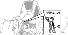
Unplug the wire-harness connector (Figure 16) from the seat.
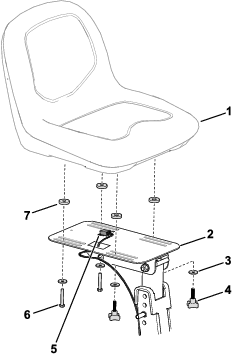
-
Remove the hardware that secures the seat to the seat mount (Figure 16) and remove the seat.
-
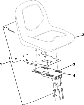
Position the spacers, heat shield, and seat on the seat mount (Figure 17).
-
Install the wire-harness connector (Figure 16) to the seat.
-
Use the previously removed hardware (Figure 16) to secure the seat and heat shield to the seat mount.
Installing the Hook-and-Loop Strap
Parts needed for this procedure:
| Hook-and-loop strap (20 inches x 1 inch) | 1 |