| Maintenance Service Interval | Maintenance Procedure |
|---|---|
| Before each use or daily |
|
Introduction
This aerator, which is controlled by a walking operator, is intended to be used by trained operators in residential and commercial applications. It is primarily designed for aerating small to mid-sized areas of well-maintained lawns on residential grounds, parks, sports fields, and on commercial grounds. Using this product for purposes other than its intended use could prove dangerous to you and bystanders.
Read this information carefully to learn how to operate and maintain your product properly and to avoid injury and product damage. You are responsible for operating the product properly and safely.
Visit www.Toro.com for product safety and operation training materials, accessory information, help finding a dealer, or to register your product.
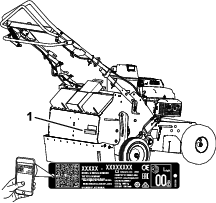
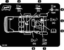
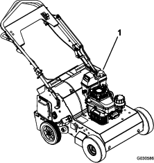
Whenever you need service, genuine Toro parts, or additional information, contact an Authorized Service Dealer or Toro Customer Service and have the model and serial numbers of your product ready. Figure 1 identifies the location of the model and serial numbers on the product. Write the numbers in the space provided.
Important: With your mobile device, you can scan the QR code (if equipped) on the serial number plate to access warranty, parts, and other product information.
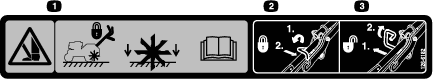
This manual identifies potential hazards and has safety messages identified by the safety alert symbol (Figure 2), which signals a hazard that may cause serious injury or death if you do not follow the recommended precautions.

This manual uses 2 words to highlight information. Important calls attention to special mechanical information and Note emphasizes general information worthy of special attention.
It is a violation of California Public Resource Code Section 4442 or 4443 to use or operate the engine on any forest-covered, brush-covered, or grass-covered land unless the engine is equipped with a spark arrester, as defined in Section 4442, maintained in effective working order or the engine is constructed, equipped, and maintained for the prevention of fire.
The enclosed engine owner's manual is supplied for information regarding the US Environmental Protection Agency (EPA) and the California Emission Control Regulation of emission systems, maintenance, and warranty. Replacements may be ordered through the engine manufacturer.
Warning
CALIFORNIA
Proposition 65 Warning
The engine exhaust from this product contains chemicals known to the State of California to cause cancer, birth defects, or other reproductive harm.
Use of this product may cause exposure to chemicals known to the State of California to cause cancer, birth defects, or other reproductive harm.
Safety
General Safety
-
This product is capable of injuring hands and feet. Always follow all safety instructions to avoid serious personal injury or death.
-
Read, understand, and follow the instructions and warnings in this Operator’s Manual and on the machine and attachments before starting the engine.
-
Be thoroughly familiar with the controls and the proper use of the equipment. Know how to stop the machine and disengage the controls quickly.
-
Do not put your hands, feet, other body parts, or clothing near or under the rotating tines or other moving parts of the machine.
-
Do not operate the machine without all proper shields, guards, and other safety protective devices in place and functioning properly on the machine.
-
Keep bystanders, especially small children, and pets out of the operating area.
-
Do not allow children to operate the machine. Allow only people who are responsible, trained, familiar with the instructions, and physically capable to operate the machine.
-
Shut off the machine and wait for all moving parts to stop before you leave the operator’s position. Disconnect the spark-plug wire, keep it away from the plug to prevent accidental starting, and allow the machine to cool before adjusting, fueling, unclogging, servicing, cleaning, or storing the machine.
Improperly using or maintaining this machine can result in injury. To reduce the potential for injury, comply with these safety instructions and always pay attention to the safety-alert symbol (Figure 2), which means Caution, Warning, or Danger—personal safety instruction. Failure to comply with these instructions may result in personal injury or death.
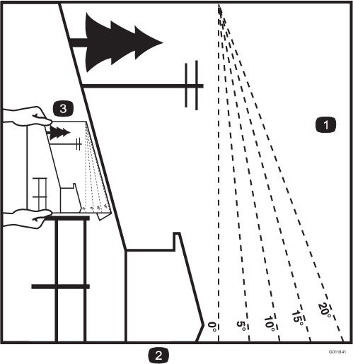
Slope Indicator
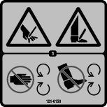
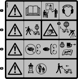
Safety and Instructional Decals
 |
Safety decals and instructions are easily visible to the operator and are located near any area of potential danger. Replace any decal that is damaged or missing. |


Setup
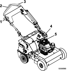
Unfolding the Handle
-
Remove the cable tie securing the upper arm to the upper handle.
-
Rotate the handle to the operating position.
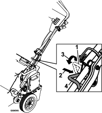
Note: Make sure that the transport latch pin is in the locked position (Figure 4).
-
Slide the oval locking rings down each side of the upper handle over the lower handle, locking the handle sections together.
Checking the Oil Level
Check the engine oil level; refer to Checking the Engine-Oil Level.
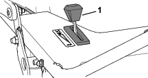
Product Overview
Tine-Control Lever
The tine-control lever lifts and lowers the rear wheels. Push down the tine-control lever to lift the wheels, transferring the weight of the machine onto the tines. Pull up the lever to lower the wheels and raise the tines (Figure 6).
Note: If you added extra optional weights to the machine, raising the tines may require significant effort.
Note: Make sure that the transport-lock pin is engaged when transporting the machine (see Figure 4).
Traction-Control Handle
The traction-control lever controls the forward, reverse, and neutral actions of the machine. Refer to Driving the Machine for more information.
Recoil Starter
Pull the recoil-starter handle to start engine (Figure 5).
Fuel-Shutoff Valve
Close the fuel-shutoff valve before you transport or store the machine.
Throttle Lever
Use the throttle lever to control the engine speed (Figure 5). Apply the engine choke by moving the throttle lever fully forward.
| Length | 150 cm (59 inches) |
| Width | 79 cm (31 inches) |
| Height | 127 cm (50 inches) |
| Weight (as shipped with 2 weights) | 172.4 kg (380 lb) |
Attachments/Accessories
A selection of Toro approved attachments and accessories is available for use with the machine to enhance and expand its capabilities. Contact your Authorized Service Dealer or authorized Toro distributor or go to www.Toro.com for a list of all approved attachments and accessories.
To ensure optimum performance, use only genuine Toro replacement parts and accessories. Replacement parts and accessories made by other manufacturers could be dangerous, and such use could void the product warranty.
Operation
Before Operation
Note: Determine the left and right sides of the machine from the normal operating position.
Before Operation Safety
General Safety
-
Do not allow children or untrained adults to operate or service the machine. Local regulations may restrict the age of the operator.
-
Operating this machine is strenuous. You must be in good physical condition and mentally alert. If you have any condition that might be aggravated by strenuous work, check with your doctor before operating this machine.
-
Shut off the machine and wait for all moving parts to stop before you leave the operator’s position. Disconnect the spark-plug wire, keep it away from the plug to prevent accidental starting, and allow the machine to cool before adjusting, fueling, unclogging, servicing, cleaning, or storing the machine.
-
Become familiar with the safe operation of the equipment, operator controls, and safety signs.
-
Check that all guards and safety devices are in place and functioning properly. Do not operate the machine unless they are functioning properly.
-
Know how to shut off the engine quickly.
-
Keep bystanders, especially small children, and pets out of the operating area.
-
Thoroughly inspect the area where you will use the machine and remove all objects that could interfere with the operation of the machine or that the machine could throw.
Fuel Safety
-
Use extreme care in handling fuel. It is extremely flammable and its vapors are explosive.
-
Extinguish all cigarettes, cigars, pipes, and other sources of ignition.
-
Do not remove the fuel cap or add fuel to the tank while the engine is running or hot.
-
Allow the engine to cool before filling the fuel tank.
-
Do not fill the fuel tank indoors.
-
Do not overfill the fuel tank. Replace the fuel cap and tighten it securely after fueling. Clean up spilled fuel before starting the engine.
-
To prevent a static charge from igniting the fuel, remove the machine from the truck or trailer and refuel it on the ground, away from all vehicles. If this is not possible, place a portable fuel container on the ground, away from all vehicles, and fill it; then refuel the machine from the fuel container rather than from a fuel-dispenser nozzle.
-
Keep the fuel-dispenser nozzle in contact with the rim of the fuel tank or container opening at all times until fueling is complete. Do not use a nozzle lock-open device.
-
If you spill fuel on your clothing, change your clothing immediately. Do not attempt to start the engine; move the machine away from the spill and avoid creating a source of ignition until the fuel vapors have dissipated.
-
If you must drain the fuel tank, do it outdoors.
-
Store fuel in an approved fuel container and keep it out of the reach of children.
-
Do not store the machine with fuel in the fuel tank or fuel container where there is an open flame, spark, or pilot light, such as on a water heater or other appliance. Allow the engine to cool before storing the machine in any enclosure.
-
Fuel is harmful or fatal if swallowed. Long-term exposure to vapors can cause serious injury and illness.
-
Avoid prolonged breathing of vapors.
-
Keep your hands and face away from the nozzle and the fuel-tank opening.
-
Keep fuel away from your eyes and skin.
-
Checking the Engine Oil Level
Check the engine oil level; refer to Checking the Engine-Oil Level.
Fuel Specification
| Type | Unleaded gasoline |
| Minimum octane rating | 87 (US) or 91 (research octane; outside the US) |
| Ethanol | No more than 10% by volume |
| Methanol | None |
| MTBE (methyl tertiary butyl ether) | Less than 15% by volume |
| Oil | Do not add to the fuel |
Use only clean, fresh (no more than 30 days old), fuel from a reputable source.
Important: To reduce starting problems, add fuel stabilizer/conditioner to fresh fuel as directed by the fuel-stabilizer/conditioner manufacturer.
Filling the Fuel Tank
Fuel tank capacity: 3.8 L (1 US gallon)
Important: Do not use fuel additives other than a fuel stabilizer/conditioner. Do not use fuel stabilizers with an alcohol base such as ethanol, methanol, or isopropanol.
-
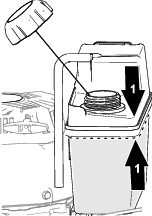
Clean around the fuel-tank cap and remove the cap from the tank. (Figure 9).
-
Fill the fuel tank with the specified fuel to within 6 mm (1/4 inch) or more from the top of the tank.
Important: Do not fill into the filler neck. Do not fill the tank more than 6 mm (1/4 inch) from the top of the tank because the gasoline needs room to expand.
-
Install the cap to the fuel tank, and wipe up any spilled gasoline.
During Operation
During Operation Safety
General Safety
-
Use your full attention while operating the machine. Do not engage in any activity that causes distractions; otherwise, injury or property damage may occur.
-
Do not operate the machine while ill, tired, or under the influence of alcohol or drugs.
-
Wear appropriate clothing, including eye protection; long pants; substantial, slip-resistant footwear; hearing protection; and gloves. Tie back long hair and do not wear loose clothing or loose jewelry.
-
Keep your hands, feet, other body parts, and clothing away from rotating tines and moving parts of the machine. The tines begin rotating when you start the engine and may continue to rotate momentarily after you shut off the engine.
-
Start the engine carefully according to instructions in this Operator’s Manual and with your feet well away from the tines.
-
Use extreme caution when reversing or pulling the machine toward you. To avoid getting pinned against a structure, allow enough distance to reverse direction near a wall or fence.
-
Keep bystanders out of the operating area. Keep small children out of the operating area and under the watchful care of a responsible adult who is not operating the machine. Stop the machine if anyone enters the area.
-
Before you start the engine, ensure that all drives are in neutral and you are in the operating position.
-
Operate the machine only in good visibility and appropriate weather conditions. Do not operate the machine when there is the risk of lightning.
-
Do not attempt to adjust the machine while the engine is running.
-
If the machine strikes an object or starts to vibrate abnormally, immediately shut off the engine, wait for all moving parts to stop, and disconnect the wire from the spark plug before examining the machine for damage. Vibration is often a warning sign of trouble. Make all necessary repairs before resuming operation.
-
Do not operate the machine at high transport speeds on hard or slippery surfaces.
-
Look behind and down and use care when reversing.
-
Do not overload the machine capacity by attempting to aerate too deep and at too fast a rate.
-
Do not pick up or carry the machine while the engine is running.
-
Exercise caution and be sure of your footing, especially when backing up, to avoid slipping or falling.
-
Be careful when operating the machine in hard ground. The tines can catch in the ground and propel the machine forward. If this occurs, let go of the machine; do not try to restrain it.
-
Exercise extreme caution when crossing gravel surfaces. Stay alert for hidden hazards or traffic.
-
Do not leave a running machine unattended.
-
Shut off the engine and wait for all moving parts to stop before you leave the operator’s position. Disconnect the spark-plug wire, keep it away from the plug to prevent accidental starting, and allow the machine to cool before adjusting, fueling, unclogging, servicing, cleaning, or storing the machine.
-
Operate the engine only in well-ventilated areas. Exhaust gases contain carbon monoxide, which is an odorless, deadly poison.
-
Use only accessories and attachments approved by Toro.
-
Do not change the engine governor settings or overspeed the engine.
-
Always be sure of your footing; keep a firm hold on the handle and walk, never run.
-
Be alert, slow down, and use caution when making turns. Look behind and to the side before reversing direction.
-
Do not operate the machine on steep slopes.
-
Allow the muffler and engine area to cool before touching them.
-
The tines should not rotate when the engine is idling; if they do rotate, contact your Authorized Service Dealer.
-
If an object becomes lodged in the tines, shut off the engine, disconnect the wire from the spark plug, and allow the engine to cool before removing the object.
Starting the Engine
-
Ensure that the spark-plug wire is connect to the spark plug.
-
Open the fuel-shutoff valve ().
-
Set the throttle lever as follows:
-
Pull the starter handle lightly until you feel resistance, then pull it sharply. Allow the rope to return to the handle slowly.
-
If you moved the throttle control to the CHOKE position, when the engine starts—move the throttle control toward the FAST position.
Note: The throttle setting governs the maximum drive speed of the machine.
Stopping the Engine
-
Release the traction control handle, and allow it to return to NEUTRAL.
-
Move the throttle lever all the way rearward to SLOW position (Figure 14).
Driving the Machine
-
To move forward, press the control lever forward (Figure 15). The further forward you push it, the faster the machine will travel.
-
To move in reverse, pull the control lever rearward (Figure 15). The further rearward you pull it, the faster the machine will travel.
Warning
The aerator tines are sharp and can puncture your feet or other body parts.
Use extreme care when moving in reverse so that you do not allow your feet to go close to the tines. Watch for and avoid obstacles you could trip over.
-
To turn the machine, move slowly and press down on the handles; turn the machine in the desired direction then resume normal operation.
-
To make zero turns, pull up on the tine ground engagement lever and raise the tines.
Important: Do not make a zero turn when the tines are down. Turning with the tines down will result in turf tearing.
-
To stop, release the control lever (Figure 15).
Aerating
-
Drive the machine to the desired location and stop it.
-
Push the tine control lever down and forward to raise the rear wheels and engage the tines.
-
Drive the machine to aerate the desired area.
Note: The machine aerates in both forward and reverse.
-
When finished, stop the machine and pull the tine control lever rearward and up to lower the rear wheels and lifts the tines out of the ground.
Important: Do not drive the machine across pavement or other hard surfaces without first raising the tines. Crossing hard surfaces with the tines lowered will damage the tines.
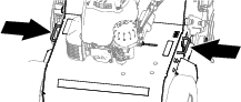
Adding Weight
The removable weights are heavy. Use care when lifting them. Make sure that you can grasp them securely before lifting them. Use caution when positioning your hands so that you do not set the weight down on your hands or fingers.
To ensure that the tines penetrate fully into the soil, you can add weight to the back of the machine. The machine has 3 weight pockets that hold the weights (Figure 17). When placing weights, ensure that you have a balance the weights across the machine. If you use only 1 weight, place it in the center pocket, and if you use 2 weights, place them in the side pockets.
Note: If you added extra optional weight(s) to the machine, raising the tines requires significant effort.
Adjusting the Coring Depth
A coring depth of 6.35 cm (2-1/2 inches) is recommended, but you can change the depth as follows:
-
Stop engine, wait for all moving parts to stop.
-
Disconnect the wire from the spark plug.
-
Loosen the nuts securing the wheel stop on the right side of the machine (Figure 18).
-
Lower the wheel stop to reduce the coring depth; raise the wheel stop to increase the coring depth.
-
Tighten the nuts securely to lock the wheel stop in place.
-
Repeat steps 3 through 5 for the wheel stop on the left side of the machine. Use the visual indicator notches in the wheel stop and indicator holes in the frame to set the wheel stops to the same height on each side (see Figure 18).
-
Connect the spark-plug wire to the spark plug.
Adjusting the Tine-Control Lever
-
Stop engine, wait for all moving parts to stop.
-
Raise the tines to the transport position.
-
Attempt to lock the transport latch pin into the lower arm; refer to Figure 19.
Note: If the pin engages and locks, the tine-control lever is correctly adjusted. If the pin does not engage or lock, then perform steps 4 through 8.
-
Disconnect the wire from the spark plug.
-
Note the location of the pin in relation to the bushing.
-
Loosen the jam nuts on the adjuster bolt (Figure 20).
Note: If the transport latch pin aligns below the bushing, rotate the bolt counterclockwise until you can lock the pin.If the transport latch pin aligns at the top of the bushing, rotate the bolt clockwise until you can lock the pin.
-
Tighten the jam nuts and verify that the transport latch pin locks and unlocks.
-
Connect the spark-plug wire to the spark plug.
Folding the Handlebar
-
Move the 2 handle-lock rings rearward (Figure 21).
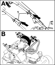
-
Fold the handlebar toward the engine.
Extending the Handlebar
-
Extend the handlebar (Figure 22).
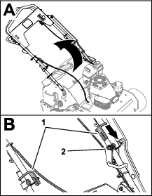
-
Move the 2 handle-lock rings forward into the slot in the lock ring is full engaged with the carriage bolts of the upper and lower handle halves.
Operating Tips
-
For best performance and maximum tine penetration, water the turf thoroughly the day before aerating.
-
Clean the area of debris before using the machine.
-
Mark and avoid shallow obstacles such as sprinkler heads and invisible fence wires.
After Operation
After Operation Safety
General Safety
-
Shut off the machine and wait for all moving parts to stop before you leave the operator’s position. Disconnect the spark-plug wire, keep it away from the plug to prevent accidental starting, and allow the machine to cool before adjusting, fueling, unclogging, servicing, cleaning, or storing the machine.
-
Clean debris from the machine to help prevent fires. Clean up oil or fuel spills.
Hauling Safety
-
Disconnect the wire from the spark plug before loading the machine for hauling.
-
Use care when loading or unloading the machine.
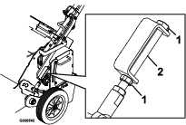
Hauling the Machine
Important: Do not operate or drive the machine on roadways.
-
Drive the machine onto a trailer, stop the machine, shut off the engine, close the fuel valve, and disconnect the spark-plug wire.
Important: If you do not close the fuel valve, the engine may flood when you haul the machine.
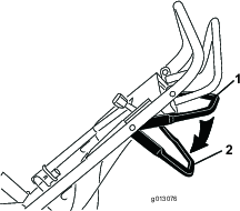
-
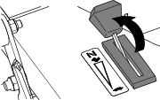
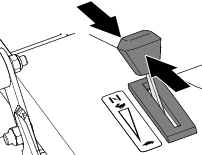
Move the transport locking pin (Figure 23) on the handle into the TRANSPORT position.
-
Lift the handle to lock it in the transport position.
-
Slide the transport latch pin through the bushing in the top of the lower arm.
-
Rotate the transport latch pin down and lock the end over the handle tube.
-
Close the fuel-shutoff valve.
-
Secure the machine to the trailer with chains or straps using the tie-down/lift loops (Figure 24).
Maintenance
Important: Refer to your engine owner’s manual for additional maintenance procedures.
Note: Download a free copy of the electrical or hydraulic schematic by visiting www.Toro.com and searching for your machine from the Manuals link on the home page.
Maintenance Safety
-
Inspect the machine frequently to ensure that it is in safe working condition and that shear bolts, engine-mounting bolts, and other fasteners are properly tightened. Replace worn or damaged parts.
-
Shut off the machine and wait for all moving parts to stop before you leave the operator’s position. Disconnect the spark-plug wire, keep it away from the plug to prevent accidental starting, and allow the machine to cool before adjusting, fueling, unclogging, servicing, cleaning, or storing the machine.
-
Keep your hands, feet, other body parts, and clothing away from rotating tines and moving parts of the machine. The tines begin rotating when you start the engine and may continue to rotate momentarily after you shut off the engine.
-
Wear gloves and eye protection when servicing the machine.
-
Never tamper with safety devices. Check their proper operation regularly.
-
To ensure optimum performance of the machine, use only genuine Toro replacement parts and accessories. Replacement parts and accessories made by other manufacturers could be dangerous, and such use could void the product warranty.
-
Replace tines that are bent, damaged, or loose; do not repair or alter them.
-
Keep the machine, attachments, and accessories in safe working condition.
-
Do not attempt to repair the machine unless you have the proper tools and instructions for disassembling, assembling, and repairing the machine.
Recommended Maintenance Schedule(s)
| Maintenance Service Interval | Maintenance Procedure |
|---|---|
| After the first 5 hours |
|
| Before each use or daily |
|
| Every 25 hours |
|
| Every 50 hours |
|
| Every 100 hours |
|
| Every 250 hours |
|
| Every 300 hours |
|
| Yearly or before storage |
|
Pre-Maintenance Procedures
Preparing for Maintenance
Caution
If you leave the spark pug wire connected, someone could accidently start the engine and seriously injure you or bystanders.
Disconnect the spark-plug wire, and ensure that the wire dose not contact the spark plug.
-
Park the machine on a level surface.
-
Shut off the engine.
-
Disconnect the spark-plug wire.
-
Wait for the engine to cool.
Important: When machine maintenance is complete, connect the spark-plug wire.
Removing the Tine Access Cover
-
Remove the 2 knobs that secure the tine access cover to the tine housing (Figure 25).
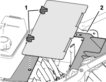
-
Tilt the cover slightly and remove the rear access cover from the machine.
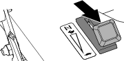
Installing the Tine Access Cover
Warning
If you operate the machine with the rear access panel removed, someone could be severely injured by contact with the moving tines or by flying debris.
Always securely install the rear access panel before operating the machine.
-
Align the tabs of the tine access cover with the opening in the tine housing (Figure 26).
-
Align the threaded shaft of the knobs with the threaded inserts in the housing.
-
Secure the cover to the housings with the knobs.
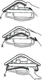
Raising the Front of the Machine
Caution
If you do not securely support the front of the machine before performing maintenance, the machine could fall on you, causing serious injury.
Support the front of the machine with a jack stand or block.
-
If you need to work on the underside of the machine, tip it backward (Figure 27).
Important: Do not tip the machine forward or you will fill the air cleaner with gasoline.
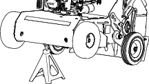
-
Support the front of the machine with a jack stand.
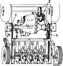
Lubrication
Greasing the Tine Shaft Bearings
| Maintenance Service Interval | Maintenance Procedure |
|---|---|
| Every 25 hours |
|
Grease Specification: NGLI grade No. 2 multi-purpose
-
Prepare the machine for maintenance; refer to Preparing for Maintenance
-
Remove the rear access panel; refer to Removing the Tine Access Cover.
-
Lubricate the grease fittings with a grease gun and the specified grease; refer to the Lubrication Chart for the fitting locations.
Lubrication Chart
Fitting Location
Initial Number of Pumps
Number of Places
1. Tine Shaft Bearings
1
2
2. Tine Assembly Idlers
1-2
2
-
Install the rear access panel; refer to Installing the Tine Access Cover.
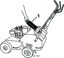
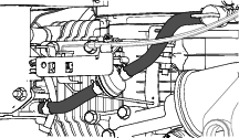
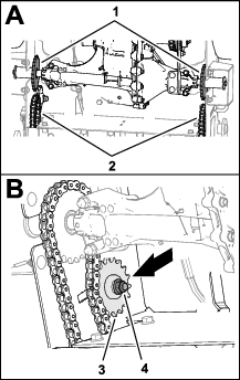
Lubricating and Checking the Drive Chains and Sprockets
| Maintenance Service Interval | Maintenance Procedure |
|---|---|
| Before each use or daily |
|
| Every 25 hours |
|
-
Prepare the machine for maintenance; refer to Preparing for Maintenance.
-
Tip up the front of the machine, and support it with jack stands; refer to Raising the Front of the Machine.
Important: Do not tip the machine forward or you will fill the air cleaner with gasoline.
-
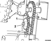
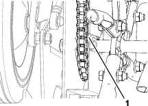
Rotate the front wheels and apply oil or chain lubricant onto the chain links of the lower spans of the front drive chains (Figure 28).
-
Check the front drive chains (Figure 28) for wear, damage, and proper tension.
Note: If chains pop or snap, replace the sprockets and chains.
-
Rotate tine shafts and apply oil or chain lubricant onto all the links of the lower spans of the tine-drive chains (Figure 28).
-
Check the chains on both sides of the machine for wear, damage, and proper tension.
Note: The chains should be able to move up and down 6 mm (1/4 inch) maximum.
Note: If chains are not tight enough or they pop or snap, adjust the chain tension; refer to Adjusting Tine-Drive Chain Tension.
-
Inspect all chain sprockets for wear and replace them as required.
-
Wipe up any oil that spilled and lower the machine to the ground
Engine Maintenance
Servicing the Air Cleaner
| Maintenance Service Interval | Maintenance Procedure |
|---|---|
| Every 25 hours |
|
| Every 300 hours |
|
Important: Do not operate the engine without the air filter assembly; extreme engine damage may occur.
-
Prepare the machine for maintenance; refer to Preparing for Maintenance
-
Remove the air-cleaner cover, and clean it thoroughly ().
Note: Be careful to prevent dirt and debris from falling into the base.
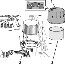
-
Remove the foam pre-cleaner and wash it with a mild detergent and water, then blot it dry (Figure 29).
-
Remove and inspect the air-filter element (); if it is excessively dirty, replace it.
Important: Do not try to clean the air-filter element.
-
Assemble the foam pre-cleaner onto the air-filter element.
Note: Use a new air-filter element if you discarded the old one.
-
Wipe dirt from the air-filter base with a moist rag.
Note: Be careful to prevent dirt and debris from entering the air duct leading to the carburetor.
-
Install the filter element onto the filter base, and install the and air-cleaner cover.
Engine Oil Specification
Service Classification: American Petroleum Institute (API) SJ or higher
Oil Viscosity: SAE 10W-30
Oil Type: detergent oil
Checking the Engine-Oil Level
-
Move the machine to a level surface.
-
Clean around the dipstick (Figure 30).
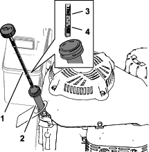
-
Loosen dipstick cap counterclockwise, and remove the dipstick from the filler neck.
-
Wipe the dipstick clean with a clean cloth.
-
Insert the dipstick into the filler neck—do not rotate the cap—then remove dipstick.
-
Read the oil level on the dipstick.
-
If the oil level is below the add mark on the dipstick, remove it, and slowly add enough of the specified oil into the filler neck to raise the oil level to the full mark on the dipstick.
Important: Do not overfill the crankcase with oil and run the engine; engine damage will result. Drain the excess oil until the oil level reaches the upper limit mark on the dipstick.
-
Insert the dipstick into the filler neck, and tighten the dipstick cap.
Engine Oil Capacity
| With oil filter | 0.85 L (29 oz) |
| Without oil filter | 0.65 L (22 oz) |
Changing the Engine Oil
| Maintenance Service Interval | Maintenance Procedure |
|---|---|
| After the first 5 hours |
|
| Every 50 hours |
|
Warning
Oil may be hot after engine has been run, and contact with hot oil can cause severe personal injury.
Avoid contacting the hot engine oil when you drain it.
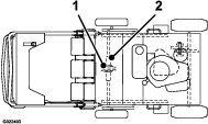
Draining the Engine Oil
-
Run the engine to warm the engine oil.
Note: Warm oil flows better and carries more contaminants.
-
Prepare the machine for maintenance; refer to Preparing for Maintenance.
-
Remove the dipstick (Figure 31).
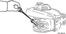
-
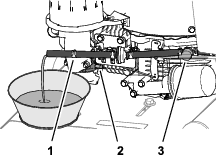
Align a drain pan along the left side of the engine.
-
Remove the oil-drain plug from the drain port of the engine (Figure 32), and tip the machine so that the oil flows into the pan.
-
Tip the machine upright again, clean the oil from the frame with a rag.
-
Install the drain plug, and tighten it to 6.9 N∙m (61 in-lb).
Adding Oil to the Engine
-
Slowly pour the specified oil into the oil fill tube, periodically checking the level with the dipstick, until the oil level is at the full mark; refer to Engine Oil Specification, Engine Oil Capacity, and Checking the Engine-Oil Level.
Important: Do not overfill the engine with oil. If you overfill the engine, pour some oil out of it.
-
Insert the dipstick into the filler neck, and tighten the dipstick cap.
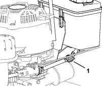
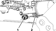
Changing the Oil Filter
Removing the Oil Filter
| Maintenance Service Interval | Maintenance Procedure |
|---|---|
| Every 100 hours |
|
-
Drain the engine oil; refer to Draining the Engine Oil.
-
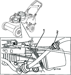
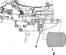
Place a rag under the oil filter (Figure 32) to catch oil when you remove the filter.
-
Remove the filter from the oil-filter adapter (Figure 33).
-
Wipe clean the mounting surface of the filter adapter.
Installing the Oil Filter
-
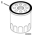
Apply a coat of the specified oil onto the gasket of the new oil filter (Figure 34); refer to Engine Oil Specification.
-
Thread the filter onto the oil-filter adapter until the gasket is flush to the adapter, then hand tighten the filter another 2/3 turn.
-
Add oil to the engine; refer to Adding Oil to the Engine
-
Connect the spark-plug wire, start the engine, and run it for 3 minutes.
-
Stop the engine, wait for all moving parts to stop, and check for oil leakage around the filter.
-
Check the engine-oil level, and add oil as needed; refer to Checking the Engine-Oil Level.
Checking the Spark Arrester
| Maintenance Service Interval | Maintenance Procedure |
|---|---|
| Every 50 hours |
|
Warning
Hot exhaust system components may ignite gasoline vapors even after you shut off the engine. Hot particles exhausted during engine operation may ignite flammable materials. Fire may result in personal injury or property damage.
Do not refuel or run engine unless spark arrester is installed.
-
Prepare the machine for maintenance; refer to Preparing for Maintenance
-
Ensure that the muffler is cool.
-
Check the spark arrester for any breaks in the screen or welds.
Note: If the spark arrester is worn or damaged, replace the arrester.
-
If the screen is plugged, remove the spark arrester, shake the loose particles out of it, and clean the screen with a wire brush (soak in solvent if needed). Replace the spark arrester when finished.
Fuel System Maintenance
Cleaning the Fuel Tank
| Maintenance Service Interval | Maintenance Procedure |
|---|---|
| Every 50 hours |
|
| Every 100 hours |
|
Emptying the Fuel Tank
The fuel filter (screen) element is located inside the fuel tank.
-
Prepare the machine for maintenance; refer to Preparing for Maintenance.
Important: Empty the fuel tank when the engine is cool.
-
Place a drain pan with a 3.8 L (1 US gallon) or greater capacity at the left side of the engine.
-
Close the fuel valve (Figure 42).
-
At the carburetor, squeeze the ends of the hose clamp together and move it away from the fuel fitting (Figure 36).
-
Disconnect the fuel hose from the fitting.
-
Align the fuel hose over the drain pan, and open the fuel-shutoff valve.
-
Wait for the fuel to completely drain from the tank, and close the shutoff valve.
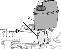
Removing and Cleaning the Tank
-
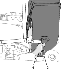
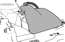
Remove the 2 flange-head bolts that secure the fuel tank to the tank-mounting bracket (Figure 37).
-
Lift the tank from the bracket (Figure 38).
-
Plug the vent hose.
-
Remove the fuel-tank cap, pour a small amount of fuel in the fuel tank, and gently shake the fuel in the tank.
-
Remove the cap from the tank, and pour the fuel into an approved fuel container.
-
Install the fuel-tank cap.
-
Remove the plug from the vent hose
Installing the Tank
-
Align the tabs of the fuel tank with the plate of the tank-mounting bracket (Figure 39).
-
Secure the tank to the flange of the tank-mounting bracket with the 2 flange-head bolts (Figure 40).
-
Assemble the fuel hose over the carburetor-fuel fitting (Figure 41).
-
Squeeze the ends of the hose clamp together and move it over the fitting.
-
Pour fuel into the tank, open the fuel-shutoff valve, and check for leaks.
Note: Repair all fuel leaks.
-
Close the fuel-shutoff valve.
Replacing the Fuel Filter
| Maintenance Service Interval | Maintenance Procedure |
|---|---|
| Every 250 hours |
|
-
Prepare the machine for maintenance; refer to Preparing for Maintenance.
Important: Replace the fuel filter when the engine is cool.
-
Close the fuel-shutoff valve.
-
Place a small drain pan under the fuel filter.
-
Squeeze the ends of the hose clamps together and move them away from the filter (Figure 42).
-
Remove the filter from the fuel hoses.
-
Install the hoses onto the fittings of the new filter (Figure 42).
-
Secure the hoses to the fittings with the hose clamps.
-
Open the fuel-shutoff valve, and check for leaks.
Drive System Maintenance
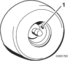
Checking Tire-Air Pressure
| Maintenance Service Interval | Maintenance Procedure |
|---|---|
| Every 50 hours |
|
Air pressure specification: 83-97 kPa (12-14 psi)
Note: To get the most accurate measurement, check the air pressure when the tires are cold.
-
Prepare the machine for maintenance; refer to Preparing for Maintenance.
-
Measure the air pressure in the tires.
-
If the air pressure is higher than or less than 83-97 kPa (12-14 psi), remove air from or add air to the tire.
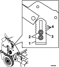
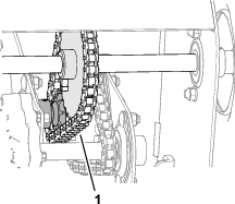
Checking Tine-Drive Chain Tension
-
Prepare the machine for maintenance; refer to Preparing for Maintenance.
-
Ensure that the tines are raised.
-
Raise the front of the machine and support it; refer to Raising the Front of the Machine.
-
Pull down on the tine-drive chain near the opening in the frame with 9 kg (20 lb) of force (Figure 44).
Note: If a chain deflects more than 3 mm (1/8 inch), adjust the chain tension; refer to Adjusting Tine-Drive Chain Tension.
-
Repeat step 4 at the other tine-drive chain.
-
Lower the machine and install the spark-plug wire.
Adjusting Tine-Drive Chain Tension
-
Loosen the nut securing the idler sprocket of the chain you are tensioning (Figure 45).
-
Pull down on the idler sprocket until the slack is taken out of the chain.
-
Tighten the idler sprocket nut and torque it to 40.6 N-m (30 ft-lb).
-
Pull down on the chain near the opening in the frame with 9 kg (20 lb) of force (Figure 44).
Note: The chain should deflect 3 mm (1/8 inch) or less.
Belt Maintenance
Checking Belt Tension
| Maintenance Service Interval | Maintenance Procedure |
|---|---|
| Every 25 hours |
|
-
Prepare the machine for maintenance; refer to Preparing for Maintenance.
-
Raise the front of the machine; refer to Raising the Front of the Machine.
-
Push on the drive belt midway between the pulleys with 9 kg (20 lb) of force (Figure 46).
Note: If the belt deflects more than 3 mm (1/8 inch), tension the belt; refer to Adjusting Belt Tension.
Adjusting Belt Tension
-
Loosen the nut that secures the idler pulley (Figure 46).
-
Push the idler pulley to the left to tighten the belt.
-
Tighten the idler-pulley nut and torque it to 40.6 N-m (30 ft-lb).
-
Push on the drive belt midway between the pulleys with 9 kg (20 lb) of force.
Note: The belt should deflect 3 mm (1/8 inch) or less.
Controls System Maintenance
Checking the Traction-Control Handle Adjustment
-
Prepare the machine for maintenance; refer to Preparing for Maintenance.
-
Ensure that the tines are raised.
-
Squeeze the traction-control handle to the handlebar until the transaxle is fully engaged.
Note: If the traction-control handle the handlebar, continue as follows:
-
Measure the gap between the traction-control handle and the handlebar.
Note: The traction-control handle is correctly adjusted if the gap is 3 mm (1/8 inch).
-
If the gap between the traction-control handle and the handlebar is less that 3 mm (1/8 inch), adjust the traction-control handle; refer to Adjusting the Traction-Control Handle.
Adjusting the Traction-Control Handle
-
Release the traction-control handle.
-
Loosen the top adjustment nut 1 turn and tighten the bottom adjustment nut.
-
Squeeze the traction-control handle to the handlebar.
-
Measure the gap between the traction-control handle and the handlebar.
Note: The traction-control handle is correctly adjusted if the gap is 3 mm (1/8 inch).
-
Repeat steps 2 through 4 until the gap is 3 mm (1/8 inch).
Hydraulic System Maintenance
Hydraulic System Safety
-
Seek immediate medical attention if fluid is injected into skin. Injected fluid must be surgically removed within a few hours by a doctor.
-
Ensure that all hydraulic-fluid hoses and lines are in good condition and all hydraulic connections and fittings are tight before applying pressure to the hydraulic system.
-
Keep your body and hands away from pinhole leaks or nozzles that eject high-pressure hydraulic fluid.
-
Use cardboard or paper to find hydraulic leaks.
-
Safely relieve all pressure in the hydraulic system before performing any work on the hydraulic system.
Changing the Hydraulic Transaxle Fluid
| Maintenance Service Interval | Maintenance Procedure |
|---|---|
| Every 100 hours |
|
Preparing the Remove the Transaxle
Caution
If you do not securely stabilize the front of the machine before service, the machine could fall on you, causing serious injury.
Use an overhead hoist to hold the machine up securely.
-
Prepare the machine for maintenance; refer to Preparing for Maintenance.
-
Ensure that the tines are raised.
-
In installed, remove the weight(s) from the machine; refer to Adding Weight.
-
Drain the fuel from the fuel tank, refer to Emptying the Fuel Tank.
-
Fold the handlebar; refer to Folding the Handlebar.
-
Slowly lift the front of the machine until the back of the machine and weight pockets are resting on the ground.
Note: Using 2 people or an overhead hoist to lift the machine will make this easier.
-
Stabilize the machine with an overhead hoist.
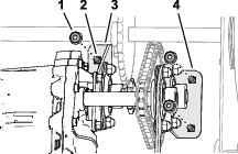
Removing the Transaxle
Note: Use 2 people or a second hoist to safely remove the transaxle.
-
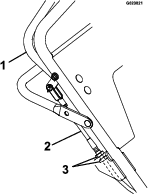
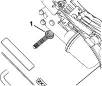
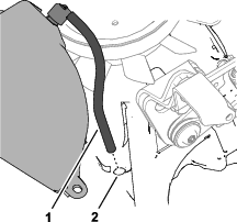
Remove the locknut (1/4 inch) that secures the fitting of the traction-control cable to the transaxle-control bracket, and separate the cable from the bracket (Figure 50).
-
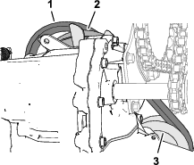
Loosen the flange locknut and capscrew that secures the belt idler pulley to the frame of the machine, move the idler pulley inboard, and remove the belt from the transaxle pulley (Figure 51 and Figure 52).
-
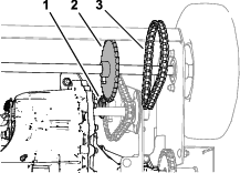
Remove and retain the connecting link from the wheel-drive-chain, and remove the chain from the transaxle sprocket and the wheel-drive sprocket (Figure 53).
-
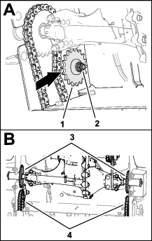
Loosen the carriage bolts and flange locknuts that secure the idler sprockets for the tine-drive chains at each side of the machine, and move the sprocket away from the chain (Figure 54).
-
Remove the connecting links from the tine-drive chains, and remove the drive chain from the front tine-drive sprockets (Figure 54).
Note: Retain the connecting links.
-
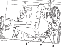
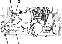
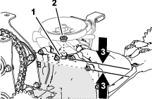
Remove the 3 flange locknuts (5/16 inch) that secure the transaxle support bracket and the bearing bracket to the machine (Figure 55).
-
While supporting the transaxle, remove the 4 flange locknuts (5/16 inch) that secure the transaxle to the axle mount, and carefully lower the transaxle to the ground (Figure 56).
Note: Retain the mounting hardware.
-
Inspect the belt, pulleys, sprockets, and bearings.
Note: Replace all worn or damaged parts.
Draining the Transaxle
-
Carefully clean the area around the expansion tank and drain/fill port.
Important: Ensure that no dirt or contamination enters the hydraulic system.
-
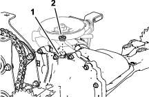
Remove the plug from the side-housing port (Figure 57).
Note: Retain the plug.
-
Rotate the transaxle over a drain pan, and fully drain oil.
Draining the Expansion Tank
-
Align the transaxle with the drain/fill port up.
-
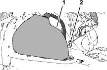
Remove and retain the screw (#10 x 1/2 inch) and release the ratchet fastener that secure the expansion tank to the housing (Figure 58).
-
Remove the expansion tank from the transaxle (Figure 59).
Note: Do not remove the vent cap from the tank.
Note: Do not remove the tank hose or O-ring unless you need to replace them.
-
Tip the expansion tank over the drain pan, and drain the oil through the transfer port.
-
Insert the vent hose of the expansion tank into the hole in the main transaxle housing (Figure 60).
-
Align the transfer port in the expansion tank over the O-ring of the transfer those, and push down to engage the ratchet fastener.
Note: Ensure that the expansion tank seals to the transaxle.
-
Secure the expansion tank to the transaxle with the screw (#10 x 1/2 inch), and torque it to 2.8 N-m (25 in-lb).
Transaxle Oil Specification
Oil type: Toro Premium Hydro Oil
Note: Mobil 1 15W50 is an acceptable alternative.
Oil quantity: approximately 2.1 L (69.3 fl-oz)
Adding Oil to the Transaxle
-
Fill the transaxle with the specified oil through the drain/fill port until the oil level is 13 to 32 mm (1/2 to 1-1/4 inches) below the top of the port (Figure 61).
-
Install the plug into the side-housing port.
Assembling the Transaxle to the Machine
-
Ensure that the belt is over the engine pulley and aligned to the idler pulley.
-
Ensure that the 4 carriage bolts (3/8 x 2-3/4 inches) are assembled to the 2 axle mounts (Figure 62).
-
Lift the transaxle, and align the holes in it with the 4 carriage bolts (3/8 x 2-3/4 inches).
-
Loosely assemble the transaxle to the carriage bolts and the axle mounts with the 4 flange locknuts (3/8 inch).
-
Loosely assemble the transaxle support bracket and the bearing bracket to the machine (Figure 63) with the 3 carriage bolts (5/16 x 3/4 inch) and the 3 flange locknuts (5/16 inch).
Assembling the Belts and Chains
-
Assemble the belt over the transaxle pulley (Figure 64).
Note: Ensure that the belt is routed around the engine and transaxle pulleys, and aligned to the idler pulley.
-
Ensure that the chains are engaged in the rear tine-drive sprockets (Figure 65).
-
Assemble the drive chains onto the front tine-drive sprockets and idler sprockets (Figure 66), and secure the chains with the connecting links.
-
Assemble the wheel-drive chain onto the transaxle sprocket and the wheel-drive sprocket, and secure the chain with the connecting link.
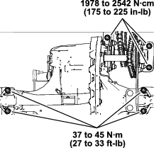
Torquing the Transaxle Hardware and Tensioning the Belt and Chains
-
Ensure that the front axle sprocket is aligned with the transaxle sprocket.
-
Torque the 3 flange locknuts (5/16 inch) and 4 carriage bolts as shown in Figure 68.
-
Torque the 4 flange locknuts (3/8 inch) and 4 carriage bolts as shown in Figure 68.
-
Tension the belt; refer to Adjusting Belt Tension.
-
Tension the tine-drive chains; refer to Adjusting Tine-Drive Chain Tension.
Installing the Traction-Control Cable
-
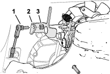
Align the fitting of the traction control cable through the hole in the transaxle-control bracket (Figure 69).
-
Secure the fitting to the bracket with the locknut.
Checking the Traction-Control Handle
-
Carefully remove the jack stand, lower the machine to the ground, and separate the machine from the overhead hoist.
-
Extend the handlebar; refer to Extending the Handlebar.
-
Check the gap between the traction-control handle and the handlebar; refer to Checking the Traction-Control Handle Adjustment.
Tine Maintenance
Checking/Replacing Tines
| Maintenance Service Interval | Maintenance Procedure |
|---|---|
| Before each use or daily |
|
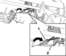
Preparing to Service the Tines
-
Prepare the machine for maintenance; refer to Preparing for Maintenance.
-
Ensure that the tines are raised.
-
Remove the tine-access panel; refer to Removing the Tine Access Cover.
-
Raise the front of the machine; refer to Raising the Front of the Machine.
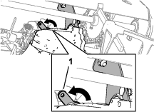
-
Move the bypass lever toward the shaft-support bracket, and secure the lever to the bracket (Figure 70).
-
Lower the front of the machine.
Checking the Tines
-
At the tine-access panel opening, inspecting the tines for wear or damage (Figure 71).
-
If the tine is worn or damaged, replace it; refer to Replacing a Tine.
-
Mark one of the tines with a piece of tape.
-
Manually rotate the tine assembly.
-
Repeat steps 1 through 4 until all the tines have been inspected.
-
Lift the front of the machine, release the bypass lever from the shaft-support bracket (Figure 72), and lower the machine.
Note: The bypass lever is spring-loaded to the transaxle-engaged position.
-
Install the tine access cover; refer to Installing the Tine Access Cover.
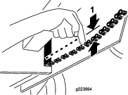
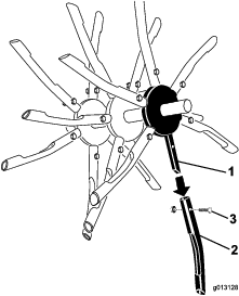
Replacing a Tine
-
Remove the flange-locknut and bolt securing the tine to the tine spider, and remove the tine (Figure 73).
-
Align the new tine the same direction as the other tines of the tine assembly.
-
Assemble the tine to the tine spider with the bolt and flange-locknut.
-
Torque the bolt and flange-locknut to 40.6 N-m (30 ft-lb).
Cleaning
Cleaning the Machine
| Maintenance Service Interval | Maintenance Procedure |
|---|---|
| Before each use or daily |
|
Important: Do not use brackish or reclaimed water to clean the machine.
Important: Do not pressure wash the machine.
Important: Avoid using excessive amounts of water near the control panel, engine, and transaxle.
-
Park the machine on a level surface, shut off the engine, remove the key, and wait for all moving parts to stop.
-
Thoroughly wash the machine.
-
Wash the machine with mild detergent and water.
-
Use a garden hose without a nozzle to avoid forcing water past the seals and contaminating bearing grease.
-
Use a brush to remove caked-on material.
-
Use mild detergent to clean the covers.
-
-
After cleaning, apply a coat of auto wax periodically to maintain the glossy finish of the cover.
-
Inspect the machine for damage, oil leaks, and component and tine wear.
Storage
Storage Safety
-
Shut off the machine and wait for all moving parts to stop before you leave the operator’s position. Disconnect the spark-plug wire, keep it away from the plug to prevent accidental starting, and allow the machine to cool before adjusting, fueling, unclogging, servicing, cleaning, or storing the machine.
-
Run the engine dry or remove the fuel with a hand pump; never siphon the fuel. If you must drain the fuel tank, do it outdoors.
-
Follow the instructions in this Operator’s Manual to safely unload, transport, and store the machine.
-
Do not store the machine with fuel in the fuel tank inside a building where ignition sources are present, such as hot water and space heaters and clothes dryers. Allow the engine to cool before storing the machine in an enclosure.
-
Always refer to the Operator’s Manual for important details if the machine is to be stored for an extended period.
Storing the Machine
-
Raise the tines, stop the machine, shut off the engine, and disconnect the spark-plug wire.
-
Wash dirt and grime from the entire machine; refer to Cleaning the Machine.
-
Service the air cleaner; refer to Servicing the Air Cleaner.
-
Grease the chains and floating tine assemblies; refer to Lubrication.
-
Change the engine oil; refer to Changing the Engine Oil.
-
Check and tighten all bolts, nuts, and screws. Repair or replace any worn or damaged parts.
-
Paint all scratched or bare metal surfaces.
Note: Paint is available from your authorized Toro service dealer.
-
Store the machine in a clean, dry garage or storage area.
-
Cover the machine to protect it and keep it clean.
Troubleshooting
| Problem | Possible Cause | Corrective Action |
|---|---|---|
| The engine does not start. |
|
|
| The machine vibrates abnormally. |
|
|
| The machine does not pull itself up hills. |
|
|
| The front wheels move but the tines do not. |
|
|
| The engine smokes when starting. |
|
|
| The engine is difficult to start after transporting it. |
|
|
| The ground speed is slow. |
|
|