Introduction

Read this information carefully to learn how to operate and maintain your product properly and to avoid injury and product damage. You are responsible for operating the product properly and safely.

You may contact Toro directly at www.Toro.com for product safety and operation training materials, accessory information, help finding a dealer, or to register your product.

Whenever you need service, genuine Toro parts, or additional information, contact an Authorized Service Dealer or Toro Customer Service and have the model and serial numbers of your product ready. The model and serial numbers are located on a plate on the breaker frame. Write the numbers in the space provided.

This manual identifies potential hazards and has safety messages identified by the safety alert symbol (Figure 1), which signals a hazard that may cause serious injury or death if you do not follow the recommended precautions.

g000502

This manual uses 2 words to highlight information. Important calls attention to special mechanical information and Note emphasizes general information worthy of special attention.

Warning

CALIFORNIA

Proposition 65 Warning

Use of this product may cause exposure to chemicals known to the State of California to cause cancer, birth defects, or other reproductive harm.

Safety

Improper use or maintenance by the operator or owner can result in injury. To reduce the potential for injury, comply with these safety instructions and those in the traction unit Operator's Manual. Always pay attention to the safety alert symbol, which means Caution, Warning, or Danger—personal safety instruction. Failure to comply with the instruction may result in personal injury or death.

Danger

There may be buried power, gas, and/or telephone lines in the work area. Shock or explosion may occur if you dig into them.

Have the property or work area marked for buried lines and do not dig in marked areas. Contact your local marking service or utility company to have the property marked (for example, in the United States, call 811 for the nationwide marking service).

Warning

The moving breaker can crush hands, feet, or other body parts.

  • Keep your hands, feet, and other part of your body or clothing away from moving parts.

  • Before adjusting, cleaning, repairing, and inspecting the breaker, lower it to the ground, stop the engine, remove the key, and wait for all moving parts to stop.

Warning

When the engine is off, attachments in the raised position can gradually lower, pinning or injuring you or bystanders.

Always lower the attachment lift each time you shut off the traction unit.

Warning

During operation, the breaker throws small pieces of broken material and dust. Flying debris may damage eyes. Inhaling the dust can damage lungs.

  • You and all bystanders must wear safety glasses, goggles, or a face shield during operation of the breaker.

  • You and all bystanders must wear a face mask or other filter over mouths and noses during operation of the breaker.

  • Keep bystanders at least 25 feet away from the breaker during operation.

Warning

The breaker is very loud during operation. Over time, your hearing may be impaired if it is unprotected.

Wear hearing protection during operation.

Warning

The breaker can cause the ground to give way and crumble from under the traction unit, causing it to become unstable and tip over, crushing you or bystanders.

  • Keep the traction unit away from the edge being broken.

  • Do not break directly under the front of the traction unit.

Warning

Within the breaker is a chamber containing pressurized nitrogen, which under the right circumstances could explode, injuring or killing you or bystanders.

  • Do not take apart the body of the breaker.

  • Do not attempt to recharge the chamber yourself. Always take the breaker to and Authorized Toro Dealer for recharging.

  • Ensure that the breaker is charged only with nitrogen. Other gases can explode.

  • Do not ship the charged breaker via air freight.

Stability ratings

To determine the degree of slope you can traverse with the attachment installed on a traction unit, find the stability rating for the hill position you want to travel in the appropriate table below, then find the degree of slope for the same rating and hill position in the Stability Data section of the Operator’s Manual for the traction unit.

Note: If you have a traction unit other than a TX series traction unit, do not use the counterweight with the breaker or the traction unit will be less stable in the front and side uphill positions.

Warning

Exceeding the maximum slope can cause the traction unit to tip, crushing you or bystanders.

Do not drive the traction unit on a slope steeper than the maximum slope.

OrientationStability Rating
Front UphillD
Graphic
Rear UphillD
Graphic
Side UphillC
Graphic

Safety and Instructional Decals

Graphic

Safety decals and instructions are easily visible to the operator and are located near any area of potential danger. Replace any decal that is damaged or lost.

decal104-6150
decal104-6151
decal106-7665

Setup

Refer to the Operator’s Manual for your traction unit for instructions on installing and removing the attachment.

Installing the Bit

  1. Park the machine on a level surface.

  2. Raise the horizontal breaker so that it is about 15 cm (6 inches) off the ground.

  3. Stop the engine and remove the key.

    Caution

    If you leave the key in the ignition switch, someone could accidently start the engine and seriously injure you or other bystanders.

    Remove the key from the ignition before you do any maintenance.

  4. Using a hammer and punch, remove the 2 elastic pins out of the breaker housing to gain access to the retaining pins (Figure 2).

    Note: Remove both front and rear pins.

    g030679
  5. Using a hammer and punch, remove the 2 bit-retaining pins from the breaker housing (Figure 2).

    Note: Removing the bit-retaining pins may require considerable force.

  6. Apply grease completely over the top 15 cm (6 inches) of the bit (Figure 2)

  7. Slide the bit into the breaker with the 2 notches in the bit in line with the retaining-pin holes (Figure 2).

  8. Hold the bit in place and insert the 2 bit-retaining pins into the breaker housing (Figure 2).

  9. Drive the pins into place with a hammer (Figure 2).

  10. Insert the 2 elastic pins into the breaker housing and drive them into place over the retaining pins with a hammer (Figure 2)

  11. Grease the bit before use; refer to Greasing the Bit.

Note: To change bits, repeat this procedure.

Operation

Important: If you have a traction unit other than a TX series traction unit, ensure that you install the Relief Valve Kit on your traction unit before using the breaker. Failure to install the kit may damage your traction unit. Refer to your Authorized Toro Dealer for more information.

Important: Always use the traction unit to lift and move the attachment.

Important: Continuous penetration in the same location for long periods of time creates high temperatures at the tip of the bit. This could cause the bit to lose its temper and mushroom under impact, destroying the bit.

Important: Never pry with the bit of the breaker.

Important: Do not use the breaker in or under water.

Converting the Breaker for Vertical Surfaces

Warning

As you lower the loader arms while changing the breaker position, the breaker swings within the frame. Hands, fingers, and feet can be caught between the breaker and the frame and be crushed or amputated.

Keep yourself and others away from the breaker while changing the position.

  1. Tilt the breaker as far forward as possible and lower it until the tip is resting on the ground.

  2. Remove the snapper pin securing the front mounting pin (Figure 3).

    g030682
  3. Remove the front breaker pin from the breaker (Figure 3).

  4. Lower the loader arms until the holes in the breaker align with the upper holes in the mount (Figure 4).

  5. Install the front mounting pin in the upper holes and secure it with the snapper pin (Figure 3).

Breaking a Vertical Surface

  1. Position the bit on the vertical surface in the same manner as you would position it on a horizontal surface.

  2. Maintain pressure on the bit by driving the traction unit forward into the vertical surface while operating the breaker.

  3. Periodically lower the the breaker to a vertical position to allow debris that may have collected in the breaker to fall out.

Selecting a Tool

Use the following table to choose the most suitable tool for operation:

ToolUse
ChiselUse for all earth-moving duties, excavations in narrow trenches, stratified soil, or rock up to medium rock.
MoilUse to demolish rocks and materials, not stratified rock, up to medium hardness.
Asphalt CutterUse to cut asphalt paving, brick walls, or turf.

Specifications

Note: Specifications and design are subject to change without notice.

Width62 cm (25 inches)
Length127cm (50 inches)
Height34 cm (13 inches)
Weight119 kg (262 lb)
Bit working length43 cm (17 inches)
Bit diameter5 cm (2 inches)
Impact energy class244 J (180 ft-lb)
Blows per minute850 to 1250
Flow range13 to 42 L per minute (4 to 11 gallons per minute)

Operating Tips

  • Wear eye, ear, and breathing protection while using the breaker.

  • If your traction unit is a TX series traction unit, use 3/4 throttle when breaking to prevent damage to the breaker.

  • If you have a traction unit other than a TX series traction unit, use full throttle (maximum engine speed), low range (turtle position) on the speed-selector lever, and adjust the flow-divider valve to approximately the 10 o’clock position.

  • Place the bit within 15 to 46 cm (6 to 18 inches) of the edge of the material to be broken, and angle the breaker slightly toward the edge (Figure 4).

    g030725
  • If the bit is positioned too far from the edge of the material, the material may absorb the energy and not break. If the material has not cracked after 15 to 20 seconds, stop the breaker and move the bit to a different location.

  • When breaking, always apply downward pressure with the loader arms until the front of the traction unit raises off the ground a few inches (Figure 4). Maintain this pressure as the bit works its way into the material being broken.

  • Do not move the auxiliary hydraulics lever to engage the breaker unless the bit is on the ground and downward pressure is applied.

  • Do not bind the bit in the material being cut. Binding of the bit can cause the bit to bend or wear out prematurely. Ensure that all force applied to the breaker is inline with the bit, not side to side or front to back. This requires frequent adjustments in the positioning of the traction unit.

  • Listen to the sound of the breaker when is operating. The sound changes when downward pressure decreases. If the downward pressure from the unit is too weak, you will hear metallic strokes from the hammer as it incorrectly strikes the bit.

  • Excessive downward pressure produces strong vibrations in the unit.

  • Many materials do not respond well to continuous hammering in one place. Each time that the breaker penetrates the material without breaking it, move it to a new location in a line parallel to the edge of the material, about 7.6 cm (3 inches) from the previous hole. This scores the material and if done repeatedly, breaks off a large piece of the material (Fig. 3).

    g030681
  • If you are breaking rebar-reinforced concrete, use a chisel bit in the breaker to cut through the rebars in the concrete. You can also cut the rebar with a torch.

Maintenance

Caution

If you leave the key in the ignition switch, someone could accidently start the engine and seriously injure you or other bystanders.

Remove the key from the ignition before you do any maintenance.

Recommended Maintenance Schedule(s)

Maintenance Service IntervalMaintenance Procedure
Before each use or daily
  • Grease the bit.Grease every 1 to 2 hours of operation and after every washing..
  • Inspect and tighten all fasteners.
  • Inspect the mounting pins, holes, lower bushing, bit-retaining pins, elastic pins, and roll pins for looseness or wear. Reseat or replace as necessary.
  • Check for hydraulic leaks in all fittings and hoses.Repair leaky fittings and/or replace leaky hoses.
  • Every 40 hours
  • Remove the bit from the breaker, wash out the cavity, and inspect the bit and bushing for excessive wear.Grease the breaker after inspection.
  • Measure the tool length.Replace the tool if the measured length is half the original length.
  • Every 500 hours
  • Check the nitrogen charge in the accumulator.
  • Greasing the Bit

    Maintenance Service IntervalMaintenance Procedure
    Before each use or daily
  • Grease the bit.Grease every 1 to 2 hours of operation and after every washing..
  • Every 40 hours
  • Remove the bit from the breaker, wash out the cavity, and inspect the bit and bushing for excessive wear.Grease the breaker after inspection.
  • Grease type: No. 1 or No. 2 general-purpose grease

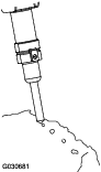
    1. Tilt the breaker so that it is vertical and lower it to the ground to push the bit up into the breaker until it stops.

      Important: If you do not push the bit up into the breaker before greasing, grease may fill the space between the top of the bit and the breaker piston. This causes the piston to pressurize the grease and damage the seal when you next use the breaker.

    2. Stop the engine and remove the key.

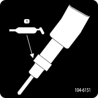
    3. Clean the grease fitting with a rag.

    4. Connect a grease gun to the fitting (Figure 6).

      g030683
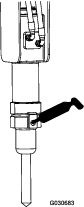
    5. Pump grease into the fitting until either grease begins to ooze out of the lower bushing and retaining pin or pumping the grease gun becomes difficult.

    6. Wipe up any excess grease.

    Charging the Nitrogen

    Maintenance Service IntervalMaintenance Procedure
    Every 500 hours
  • Check the nitrogen charge in the accumulator.
  • Inside the breaker is an accumulator, a chamber of pressurized nitrogen. After several hours of use the pressure may decrease, reducing the performance of the breaker.

    Strong vibrations in the auxiliary hydraulic hoses are a sign the pressure is dropping in the chamber. If this should happen, bring the breaker to your Authorized Toro Dealer to be charged.
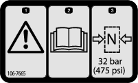
    Warning

    Within the breaker is a chamber containing pressurized nitrogen, which under the right circumstances could explode, injuring or killing you or bystanders.

    • Do not take apart the body of the breaker.

    • Do not attempt to charge the chamber yourself. Always take the breaker to an Authorized Toro Dealer for charging.

    • Ensure that the breaker is charged only with nitrogen. Other gases can explode.

    • Do not ship the charged breaker via air freight.

    Storage

    1. Wash the attachment with mild detergent and water to remove dirt and grime.

    2. Grease the bit.

    3. Check and tighten all bolts, nuts, and screws.

    4. Inspect all mounting pins, holes, the lower bushing, roll pins, and the bit-retaining pin. Repair or replace any part that is damaged or worn.

    5. Inspect all hydraulic fittings and hoses for leaks. Repair or replace any fittings or hoses that leak.

      Warning

      Hydraulic fluid escaping under pressure can penetrate skin and cause injury. Fluid accidentally injected into the skin must be surgically removed within a few hours by a doctor familiar with this form of injury or gangrene may result.

      • Keep body and hands away from pin hole leaks or nozzles that eject high pressure hydraulic fluid.

      • Use cardboard or paper to find hydraulic leaks; never use your hands.

    6. Paint all scratched or bare metal surfaces. Paint is available from your Authorized Service Dealer.

    7. Store the breaker in a vertical position in a clean, dry garage or storage area. Cover it to protect it and keep it clean.

      Important: If you are storing the breaker for more than a month, store it vertically to avoid damaging O-rings and seals inside the breaker.

    Troubleshooting

    ProblemPossible CauseCorrective Action
    The breaker does not operate.
    1. A hydraulic coupler is not completely connected.
    2. A hydraulic coupler is damaged.
    3. There is an obstruction in a hydraulic hose.
    4. An auxiliary valve on the traction unit does not open.
    5. The nitrogen level in the breaker is low.
    1. Check and tighten all couplers.
    2. Check all couplers and replace any damaged couplers.
    3. Find and remove the obstruction.
    4. Repair the valve.
    5. Contact your Authorized Toro Dealer.