Installation
Preparing the Machine
-
Park the machine on a level surface.
-
Engage the parking brake.
-
Lower the cutting units.
-
Shut off the machine and remove the key.
-
Disconnect the main-power connectors; refer to your machine Operator’s Manual.
Raising the Machine
Raise the machine; refer to the pre-maintenance section of your machine Operator’s Manual.
Removing the Front Wheel
Note: If you are replacing a left-hand side motor (Model No. 147-3052 or 147-3054), remove the left, front wheel. If you are replacing a right-hand side motor (Model No. 147-3051 or 147-3053), remove the right, front wheel.
-
Loosen and remove the wheel lug nuts (Figure 1).

-
Remove the tire.
Removing the Front Wheel Hub
-
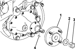
Loosen the front hub locknut at least 2 revolutions.
-
Use a 3-jaw puller to loosen the front hub assembly from the gearbox shaft.
Important: Do not hit the front wheel hub or gearbox assembly with a hammer when removing the front hub. Hammering the assembly may damage the gearbox.
-
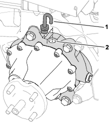
Remove wheel hub by removing the corresponding wheel hub locknut and washer (Figure 2).
-
Remove the woodruff key (Figure 2).
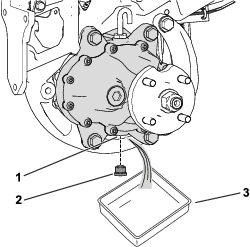
Draining the Traction-Motor-Gearbox Fluid
Removing the Existing Motor
-
If you are replacing a traction motor (Part No. 147-3051 or 147-3052), remove the existing motor as follows:
-
Remove and retain the gearbox and corresponding hardware from the existing motor assembly; refer to your machine Service Manual.
-
Remove and discard the existing motor assembly; refer to your machine Service Manual.
-
-
If you are replacing a wheel motor (Part No. 147-3053 or 147-3054), remove and discard the existing motor assembly; refer to your machine Service Manual.
Installing the Wire Harness Adapter
Parts needed for this procedure:
| Motor assembly | 1 |
| Wire harness motor adapter | 1 |
| Open-end splice | 6 |
| Closed-end splice | 1 |
-
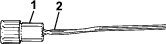
Cut off the existing motor adapter from the motor wire harness.
-
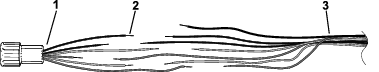
Stagger the ends of the harness wires slightly to avoid splices from being in one location or section of the harness; refer to Figure 5.
-
Cut the wires on the new adapter to the appropriate length (Figure 5).
-
Strip off approximately 9.5 mm (3/8 inch) of insulation from the 6 adapter wires and 7 harness wires (Figure 5).
Important: Be careful and ensure that you do not damage the wire strands when stripping the insulation.
-
Ensure that the wire insulation is clean and the copper wire is not corroded for the splice adhesive to bond properly.
-
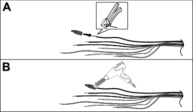
On the existing wire harness, install the closed-end spice onto 1 of the gray wires using a crimping tool that matches position (22-14 AWG); refer to A of Figure 6.
Note: When crimping the splice, do not damage the insulation.
-
Use an appropriate heat gun to shrink the splice insulation until the adhesive has squeezed out (B of Figure 6).
Note: Do not overheat or burn the insulation.
-
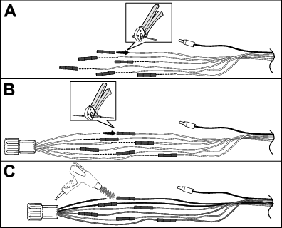
On the existing wire harness, install an open-end splice onto the 6 remaining wires end one at a time using a crimping tool that matches position (20-18 AWG); refer to A of Figure 7.
Note: When crimping the splice, do not damage the insulation.
-
Insert each of the motor adapter wires into the corresponding open-end splice, matching the insulation color of the wires, and crimp the connector securely (B of Figure 7).
-
Use an appropriate heat gun to shrink the splice insulation until the adhesive has squeezed out from each end (C of Figure 7).
Note: Do not overheat or burn the insulation.
Installing the Motor
-
If you are replacing a traction motor (Part No. 147-3051 or 147-3052), install the gearbox (removed in Step 1 of Removing the Existing Motor) onto the new motor. Refer to your machine Service Manual.
-
Install the motor assembly on the machine; refer to your machine Service Manual.
Installing the Front Wheel Hub
Filling the Traction-Motor-Gearbox Fluid
Important: The machine must be level so that the correct amount of fluid can be added to the gearbox.Ensure that the machine is level on the jack stands.
Installing the Front Wheel

Completing the Installation
-
Lower the machine to the ground.
-
Connect the main-power connectors; refer to your machine Operator’s Manual.
-
Test the front traction motors; refer to your machine Service Manual.
-
Calibrate the front traction motors; refer to your machine Service Manual.