Installation
Preparing the Machine
-
Park the machine on a level surface.
-
Engage the parking brake.
-
Lower the cutting unit.
-
Shut off the machine and remove the key.
-
Remove the flail mower from the machine; refer to the flail mower Operator’s Manual.
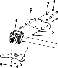
Removing the Gearbox, Belt, Pulleys, and PTO Guard
Removing the PTO Guard
Removing the Belt and Pulleys
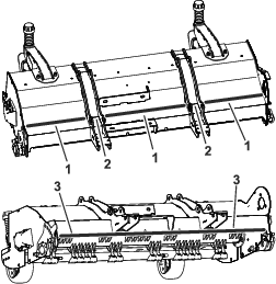
Welding the Flail Mower
Parts needed for this procedure:
| Toro spray paint | 1 |
Figure 6 indicates the continuous weld areas that must be added to the flail mower.
-
Remove any paint from the indicated weld areas to ensure a continuous weld.
-
Weld the areas shown in Figure 6.
Important: Ensure that the welds are continuous without gaps or skips.Do not weld between the lift-arm plates (Figure 6).
-
Remove any weld splatter and ensure that all surfaces are clean.
-
Spray paint the newly welded areas.
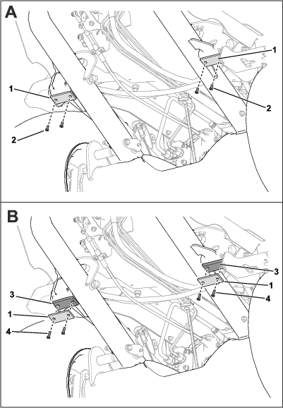
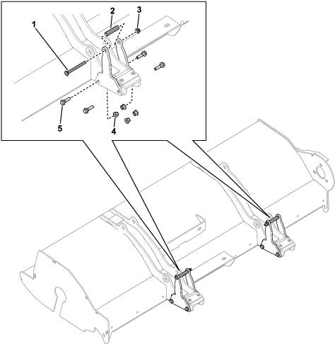
Installing the Lift-Arm Brackets
Parts needed for this procedure:
| Lift-arm bracket | 4 |
| Bolt (M10 x 35) | 8 |
| Flange nut (M10) | 8 |
| Spacer | 2 |
| Carriage bolt (3/8 inch x 4 inches) | 2 |
| Flange nut (3/8 inch) | 2 |
-
Mark a line on a lift-arm plate as shown in Figure 7.
-
Align a lift-arm bracket to the marked line and the lower edge of the frame (Figure 8).
-
Mark the bracket holes on the frame (Figure 8).
-
Repeat the previous steps for each side of the lift-arm plates (Figure 7).
-
Drill 8 holes (10 mm) into the marks on the lift-arm plates (Figure 8).
-
Use 8 bolts (M10 x 35), 8 flange nuts (M10), 2 carriage bolts (3/8 inch x 4 inches), 2 spacers, and 2 flange nuts (3/8 inch) to secure the lift-arm brackets to the frame (Figure 9).
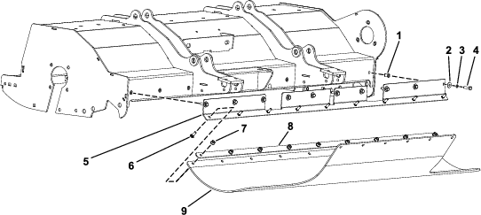
Installing the Debris Skirt to the Flail Mower
Parts needed for this procedure:
| Debris skirt | 1 |
| Skirt mount bracket | 1 |
| Long rubber securing bracket | 1 |
| Clinch nut (M8) | 10 |
| Hex-head bolt (M8 x 30) | 10 |
| Spring washer | 10 |
| Flat washer | 10 |
| Carriage bolt (M8 X 25) | 9 |
| Flange nut (M8) | 9 |
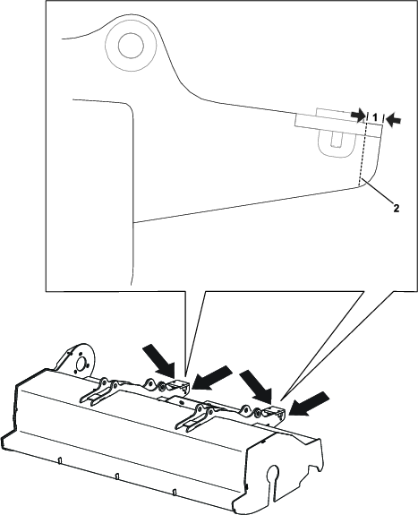
Adding Bracket-Alignment Lines to the Frame
Using a non-permanent marker, mark the following lines onto the frame:
-
21 mm (13/16 inch) from the flail side plate
-
80 mm (3-1/8 inches) up from the lower outer edge of the rear plate
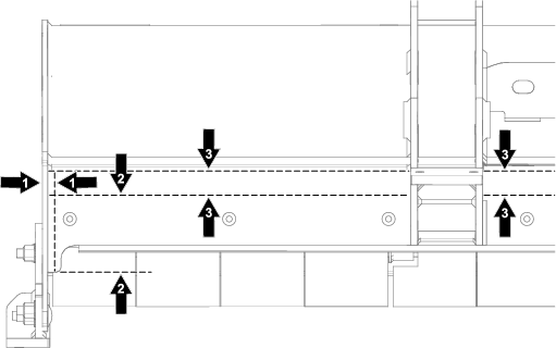
Drilling Holes and Installing Clinch Nuts to the Frame
-
With an assistant, align the edges of the skirt mount bracket with the marked lines and mark the holes for the 2 outside mount-bracket holes.
-
Drill holes (11 mm) in the 2 marked outer holes.
-
Install 2 clinch nuts into the drilled outer holes.
-
Install the skirt mount bracket to the clinch nuts.
-
Mark the remaining 8 holes in the skirt mount bracket.
-
Remove the skirt mount bracket.
-
Drill holes (11 mm) in the 8 marked holes.
-
Install 8 clinch nuts into the drilled holes.
-
Install the skirt mount bracket to the clinch nuts.
Securing the Skirt Mount Bracket to the Frame
Use 10 flat washers, 10 spring washers, and 10 hex-head bolts (M8 x 30) to secure the skirt mount bracket to the clinch nuts on the frame.
Installing the Debris Skirt
Use 9 carriage bolts (M8 X 25), the long rubber securing bracket, and 9 flange nuts (M8) to secure the debris skirt to the skirt mount bracket.
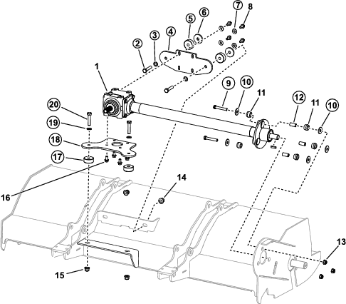
Installing the Gearbox
Parts needed for this procedure:
| Gearbox | 1 |
| Flange nut (7/16 inch) | 3 |
| Rubber bushing | 6 |
| Flange nut (M12) | 4 |
| Hex-head bolt (3/8 x 7/8 inch) | 4 |
| Hex-head bolt (3/8 x 3/4 inch) | 4 |
Installing the Gearbox to the Mounting Plate
-
Ensure the threads in the gearbox, mounting plate, and gearbox mounting faces are clean.
-
Apply high-strength thread-locking compound to the 4 hex-head bolts (3/8 x 3/4 inch).
-
Use 4 hex-head bolts (3/8 x 3/4 inch) to secure the gearbox to the mounting plate (Figure 12).
Torque the bolts to 45 N∙m (33 ft-lb).
Installing the Gearbox to the Back Plate
-
Apply medium-strength thread-locking compound to the 4 hex-head bolts (3/8 x 7/8 inch).
-
Loosely assemble the previously removed 2 bolts (M12 x 60) and M12 washers into the back plate (Figure 12).
-
Use 4 hex-head bolts (3/8 x 7/8 inch) and the previously removed washers to loosely secure the back plate to the gearbox (Figure 12).
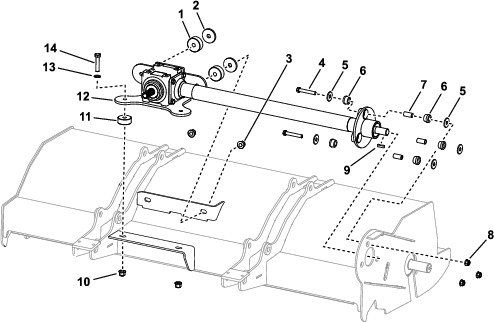
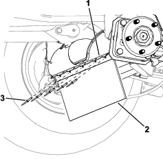
Installing the Gearbox to the Flail Mower
Refer to Figure 13 for this procedure.
-
Insert the new rubber bushings and the existing metal spacers into the 3 positions on the end of the gearbox.
-
Lower the gearbox into the frame partially inserting the gearbox output shaft through the frame.
-
Ensure that all the spacers are installed in the correct positions and insert the M12 bolts, washers, spacers, and nuts. Leave these fasteners loose.
-
Ensure the key supplied with gearbox is fitted in keyway.
-
Use the rubber bushings, washers, and the previously removed hardware to loosely assemble the gearbox output shaft to the frame.
Ensure that washers are installed to both sides of the rubber bushings.
-
Ensure that the gearbox is sitting correctly and none of the fasteners are tightened.
The gearbox assembly must be able to slide on its mountings as the gearbox is tightened.
-
Gradually tighten the fasteners as follows:
-
Torque the hex-head bolts (7/16 x 2-3/4 inches) shown in Figure 13to 60 N∙m (44 ft-lb).
-
Torque the bolts (M12 X 60) shown in Figure 12 to 100 N∙m (74 ft-lb).
-
Torque the hex-head bolts (M12 x 60) shown in Figure 13 to 100 N∙m (74 ft-lb).
-
Torque the hex-head bolts (3/8 x 7/8 inch) shown in Figure 12 to 45 N∙m (33 ft-lb).
-
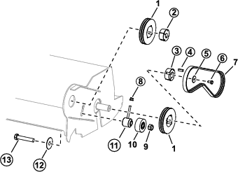
Installing the Belts and Pulleys
Parts needed for this procedure:
| Pulley | 2 |
| Idler pulley | 1 |
| Thin nut (M20) | 1 |
| Belt | 1 |
| Spacer | 2 |
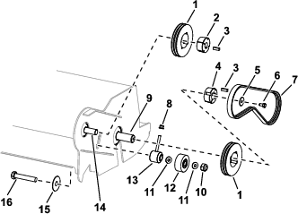
Installing the Pulleys
Refer to Figure 14 for this procedure.
-
Ensure the keys are fitted to the rotor and gearbox shafts.
-
Slide the new pulleys and existing bushings onto the shafts and rotate the pulleys to align the tapped holes.
-
Loosely fit the grub screws to the pulleys. Lightly tighten the grub screws so the pulleys can still be moved on the shaft.
-
Use a straight-edge tool to align the pulleys.
Ensure that the pulleys are secured past the chamfered edge on the flail-rotor and gearbox shafts.
-
Install a new spacer to the existing bolt (M20 x 110), install the new idler pulley, and the new outside spacer.
-
Ensure that all tension is removed from the tensioning spacer.
Installing the Belt
Refer to Figure 14 for this procedure.
-
Install the belt around the pulleys.
-
While holding the pulleys, tighten the pulley grubscrews to 30 N∙m (22 ft-lb).
Ensure that the pulleys remain aligned.
-
Apply medium-strength thread-locking compound to the bolt (M20 x 110) threads.
-
Install the nut (M20); tighten the nut enough so that the tensioning spacer can still be adjusted.
-
Check the belt tension; refer to the belt-tensioning procedure in the flail mower Operator’s Manual.
-
Tighten the nut (M20) to 100 N∙m (74 ft-lb).
-
Check the belt tension.
-
Apply medium-strength thread-locking compound to the flail-rotor shaft. Install the washer (M10) and bolt (M10 x 30) that were previously removed from the flail-rotor shaft.
-
Install the belt cover.
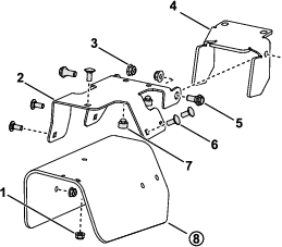
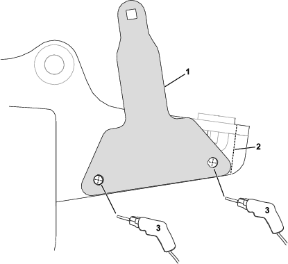
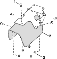
Removing the Debris Guard from the Traction Unit
Remove the debris guard and bracket from the traction unit as shown in Figure 15.
Note: You can discard the bracket and the rivets.
Using the Guard Bracket to Install the Debris Guard
Parts needed for this procedure:
| Guard bracket | 1 |
| Rivet | 5 |
Use 5 rivets and the new guard bracket to secure the debris guard to the front axle (Figure 16).
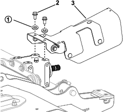
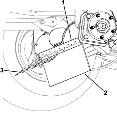
Replacing the Sensor Bracket
Parts needed for this procedure:
| Sensor bracket | 1 |
| Carriage bolt (3/8 x 1-1/4 inches) | 2 |
| Flange nut (3/8 inch) | 2 |
-
Remove the existing sensor bracket from the traction-unit right lift arm.
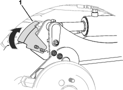
-
Use 2 carriage bolts (3/8 x 1-1/4 inches) and 2 flange nuts (3/8 inch) to secure the new sensor bracket to the right lift arm.
Rotate the bracket up (Figure 17) before securing it.
Installing the Flail to the Traction Unit
Install the flail mower to the traction unit; refer to the flail mower Operator’s Manual.
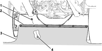
Installing the Debris Skirt to the Traction Unit
Parts needed for this procedure:
| Flap mount | 1 |
| Carriage bolt (M8 x 25) | 6 |
| Flange nut (M8) | 6 |
Use 6 carriage bolts (M8 x 25), 6 flange nuts (M8), and the flap mount to secure the debris skirt to the axle bracket.
Note: For easier access to this area, you may remove a front wheel or both front wheels. Refer to the Setup section in the traction unit Operator’s Manual for wheel removal and installation instructions.
Installing the PTO Guard
Parts needed for this procedure:
| PTO guard-bracket assembly | 1 |
| Screw (3/8 x 3/4 inch) | 2 |
| Carriage bolt (5/16 x 3/4 inch) | 5 |
| Flange nut (5/16 inch) | 5 |
Adjusting the Sensor Bracket
The sensor and the sensor-bracket plate should have a 6 mm (0.24 in) clearance between them (Figure 21).
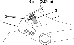
If the clearance is incorrect, perform the following steps to adjust the sensor bracket:
-
Loosen the locknuts that secure the switch to the switch bracket and adjust it so that the correct clearance exists between the sensor and the sensor plate.
-
Tighten the sensor locknuts from 19 to 21 N·m (14 to 16 ft-lb).
Updating the Traction-Unit Software
Use Toro DIAG to update the traction-unit software to Rev E; refer to the Toro DIAG SoftwareUser’s Guide.
Checking the Gearbox Lubricant
Ensure that the gearbox has the correct amount of lubricant; refer to the flail mower Operator’s Manual.
Greasing the Cutting Unit
Grease the cutting unit before the first operation; refer to the flail mower Operator’s Manual. Failure to properly grease the machine will result in premature failure of critical parts.
Engaging the Turnaround Mode
Use the traction-unit display screen to engage Turnaround mode; refer to your traction unit Operator’s Manual.
Important: Using Turnaround mode with an equipped flail mower helps prevent premature driveline wear. You must always have Turnaround mode engaged when mowing with the flail.
Note: Turnaround mode allows you to quickly raise the flail mower above the turf when completing a quick turn at the end of a mowing pass (or while navigating around obstacles) without disengaging the PTO.
Reducing the Engine Speed before PTO Engagement
Reducing the Engine Speed before PTO Engagement
Before you engage the PTO with an equipped flail, use the traction-unit throttle control to adjust the engine to a medium speed. Once you engage the PTO, use the throttle control to increase the engine speed to full speed.
Important: Reducing the engine speed prior to engaging the PTO with the flail helps prevent premature driveline wear.
Engaging the
Use the traction-unit display screen to engage LOW RPM PTO ENGAGE mode; refer to your traction unit Operator's Manual.
Note: LOW RPM PTO ENGAGE mode automatically reduces the engine speed when the PTO is engaged, then automatically raises the engine speed to full speed.
Important: Using LOW RPM PTO ENGAGE mode with the flail helps prevent premature driveline wear.
Installing Spacers to the Front Frame
Parts needed for this procedure:
| Spacer | 2 |
| Screw (1/4 x 1-1/4 inch) | 4 |
For traction units that have a Cab Kit and a Road Light Kit equipped, the flail mower could contact the road lights. To avoid contact with the road lights, install the spacers to restrict movement of the lift arms.
-
Under the front chassis, remove the existing screws (1/4 inch) and rubber pads from the chassis (Figure 22).
Discard the screws and retain the pads.
-
Use the new screws (1/4 x 1-1/4 inch) to secure the spacers and rubber pads to the chassis (Figure 22).
Tighten the screws until the heads are flush with the rubber pads.